Page is loading ...

2006 Thermaltake Technology Co., Ltd. All Rights Reserved.
All other registered trademarks belong to their respective companies.
C
The Ideal Home
Entertainment Center

Chapter 1. Product Introduction
Chapter 2. Case Mechaniacl Operation
Chapter 3. Motherboard & Leads Installation
Chapter 4. Other
1.1 Specification
2.1 How to open the side panel
2.2 5.25"device installation
2.3 3.5" device installation
2.4 Tool-free PCI slot Usage
2.5 Power Supply Unit Installation
3.1 Motherboard Installation
3.2 Case LED Connection
3.3 Case Open Alarm Connection
3.4 USB 2.0 & IEEE 1394 Firewire Connection
3.5 Audio Connection
4.1 Media LAB (VFD display) Installation (Optional)
4.2 7"LCD monitor Installation (Optional)
4.3 Secondary System Mini ITX Installation(Optional)
01
03
04
06
08
09
11
13
13
14
16
18
20
23
3.6 eSATA connection
17
Contents
ontents
C

AluminumCase Panel Material
1. 7" Bay LCD monitor
2. Media LAB : VFD / Remote control / software
3. Mini ITX Kit : 270W 5.25" PSU / PWR &
Reset module / 100 cm SATA & IDE cable
4. BTX Kit : SRM / Rear plate
Upgraded Kit
(optional)
7Expansion Slots
eSATA connector, USB 2.0 x 4, IEEE 1394,
Firewire, HD-Audio
Front I/O
- 7" x 1
- 5.25" x 5
- 3.5" x 7 (Exposed x 1, Hidden x 6)
Drive Bays
- Primary: ATX, Micro ATX, BTX, Micro BTX,
Nano BTX, Pico BTX
- Secondary : Mini ITX
Motherboard
- Front : 12cm fan x 2 (up to five 12cm fan)
- Rear : 12cm fan x 3 (up to five 12cm, one 8cm fan)
Cooling System
BlackColor
SECCCase Body Material
N/AWindowWindow side panel
330 x 360 x 720 mm (W*D*H)Dimension
Cube TowerCase Type
VE1000BNSVE1000BWSModel
AluminumCase Panel Material
1. 7"Bay LCD monitor
2. Media LAB : VFD / Remote control / software
3. Mini ITX Kit : 270W 5.25" PSU / PWR &
Reset module / 100cm SATA & IDE cable
4. BTX Kit : SRM / Rear plate
Upgraded Kit
(optional)
7Expansion Slots
eSATA connector, USB 2.0 x 4, IEEE 1394,
Firewire, HD-Audio
Front I/O
- 7" x 1
- 5.25" x 5
- 3.5" x 7 (Exposed x 1, Hidden x 6)
Drive Bays
- Primary: ATX, Micro ATX, BTX, Micro BTX,
Nano BTX, Pico BTX
- Secondary : Mini ITX
Motherboard
- Front : 12cm fan x 2 (up to five 12cm fan)
- Rear : 12cm fan x 3 (up to five 12cm, one 8cm fan)
Cooling System
SilverColor
AluminumCase Body Material
N/AWindowWindow side panel
330 x 360 x 720 mm (W*D*H)Dimension
Cube TowerCase Type
VE1000SNAVE1000SWAModel
VE1000SWA
VE1000SNA
VE1000BWS VE1000BNS
Chapter 1. Product Introduction
1.1 Specification
01 02

Chapter 2. Case Mechaniacl Operation
2.1 How to open the side panel
Please find the side panel key in
the back of the chassis, then
unlock it as shown.
Make sure the side panel
lock is opened, push the
button then swing out the
side panel.
1
2
2.2 5.25"device installation
1
2
Firstly, please release the
thumb screws of HDD cage
shown as picture.
Push down and hold the metal
tab then pull the cage out-ward
to remove from chassis.
Remove the screws on the
both side of 5.25"cage.
03 04

3
Remove the 5.25" cover.
4
5
Insert the device into the desired
location of 5.25" drive bay then slide
it along the fixed-positioning rack
inside the cage.
Push back the plastic rail to
secure the device.
2.3 3.5" device installation
1
2
3
4
Unscrew the screws on the
both side of 5.25"cage.
Remove the 3.5" bay cover if you
would like to install Floppy Disk Drive.
(If no, please see the step 5)
Insert Floppy Disk Drive into the cage
Secure FDD with screws from the both
side of the cage labeled "FDD".
05 06

Insert hard drive disk into the
desired location of cage
5
6
7
Install back the HDD cage.
Secure hard drive disk with
enclosed screws from the
both side of the cage.
2.4 Tool-free PCI slot Usage
1
2
3
4
Squeeze and pull out-ward
the tool-free clip securing the
PCI bracket.
Take off the PCI bracket.
Locate the graphic card to the
motherboard through fixing it
on the space of PCI bracket
and insert it to the PCI slot.
Push back the clip to secure
the graphic card.
07 08

2.5 Power Supply Unit Installation
1
2
3
4
Install power supply unit as
shown picture
Secure the unit from the
rear with 4 screws
Secure the unit
with one thumb
screw as shown
picture.
Finish
Important Notice -
Contents below are additional information for proper
motherboard installation for Thermaltake Chassis.
Please find out the mylars types from
the accessory box (clear plastic films)
*Note: Due to the unique design of the
Chassis, these Mylar tapes are
included to prevent ATX motherboards
from contacting the chassis.
Remove the adhesive backing and
place the Mylars over each
locations as shown.
Completed. Please note the Mylar
tapes included are transparent.
The image here is for
reference only.
Chapter3 Motherboard & Leads Installation
09 10

How to open the front panel
1
2
Open the both side panels,
find out the 6 springs which
are circled in the pictures.
Push every spring to
release the front panel.
3.1 Motherboard Installation
Each motherboard has different standoff layout. It is highly
suggested that you refer to your motherboard's manual when
installing motherboard into the Case. The cases are applicable with
Standard ATX and Micro ATX motherboards.
Your motherboard may require a special I/O Panel, which should be
included with your motherboard.
Placement Direction:
When installing the motherboard, make sure you follow the direction
provided by your motherboard manufacturer. On most standard
motherboards, the edge with external ports goes to the rear part of the
chassis. It is highly recommended that you install CPU, heat sink and
modular components before fixing the motherboard inside the chassis.
= the locations of
the screw holes. Note
these locations and
place included
standoffs on the chassis
first.
This side towards
the rear of the
chassis
Above illustration is a sample of what
the motherboard's layout. For more
detail screw hole placement, please
refer to your motherboard manual.
11 12

3.4 USB 2.0 & IEEE 1394 Firewire Connection
Please consult your motherboard manual to find
out the section of "USB connection".
USB connection
3.2 Case LED Connection
On the front of the case, you can find some LEDs and switch leads
(POWER SW*1, POWER LED*1, H.D.D. LED*1, RESET SW*1)
Please consult user manual of your motherboard manufacturer, then
connect these leads to the panel header on the motherboard. These
leads are usually labeled; if not, please trace them back to the case
front to find out their source.
- POWER LED connects to your M/B at the PLED
- POWER SW connects to the PWR connector on the motherboard.
- H.D.D LED connects to the eSATA connector shown as picture(3.5)
- RESET SW connects to the RSW connector on the motherboard,
3.3 Case Open Alarm Connection
1
2
To find out the cable with 2pin
connector ("Micro SW") from the
rear of inside the chassis.
To find out the position of Chassis
Alarm on your motherboard.
(please consult your motherboard
manual)
White Wire
Black Wire
( Brank )
GND2
Data+2
Data-2
Vcc2
GND1
Data+1
Data-1
Vcc1
USB2.0
13 14

IEEE1394 Firewire connection
Please consult your motherboard manual to find
out the section of "IEEE1394 Firewire connection".
SHIELD
VPVP
TPB+
VG
TPA+
TPB-
VG
TPA-
IEEE1394
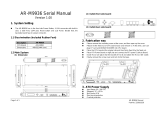
3.5 Audio Connection
Return L
( Brank )
Spekout R
MIC BIAS
MIC IN
SHIELD
GND
HD AUDIO
Splout L
Return R
Return L
( Brank )
Spekout R
MIC BIAS
MIC IN GND
AC'97
Splout L
Return R
( Brank )
15 16
Please check your motherboard ,does it support AC'97
or HD-Audio , choose one of them to connect.

3.6 eSATA connection
Connect this to your
motherboard at the
"HDD LED". arrow
means "+"
Connect this to your
power supply unit
Connect this to your
motherboard at SATA.
4.1 Media LAB (VFD display)
Installation (Optional)
1
2
3
Please remove the front panel (See
"how to open the front panel" )
Remove the 4 screws
from 5.25" Media LAB
Screw on the core of the Media
LAB onto the designated VFD
Window location.
Chapter4 Other
17 18

4
Please connect the Power SW
connector to the PWR_SW
connectors on the VFD core as
shown.
Installation complete, please re-
install the front panel and the
chassis casing of the Mozart TX
chassis
5
4.2 7"LCD monitor Installation (Optional)
1
2
Unscrew the both side screws
of 7" drive bay cover.
Pull out the both side clips
then remove the cage one the
7"drive bay monitor.
19 20

3
4
Install the 7" cage onto
the 7" drive bay
Push all the metal clips
to fix the cage.
5
6
Insert the 7"device
Install the frame.
21 22

4.3 Secondary System Mini ITX Installation
(Optional)
1
2
3
This mini ITX upgrade kit (optional) includes following items
5.25" PSU -270W (Please
install to 5.25" drive bay)
IDE data cable x 1
SATA data cable x 1
Power on/off and Reset switch (please install to 5.25"drive bay
then connect these to mini ITX motherboard)
This side towards the
rear of the chassis.
The circles mean the screw holes of mini ITX
23 24
Secondary System Mini ITX Installation(Optional)
/