Page is loading ...

1
STATCLAVE G4 Service Manual
1. UNIT OVERVIEW ............................................................................................................................................ 4
Introduction ...................................................................................................................................................... 4
Principles of operation ...................................................................................................................................... 4
Steps in a typical cycle ................................................................................................................................... 4
Diagram of key systems and components ........................................................................................................ 5
Front and back of the unit................................................................................................................................. 7
Top of the unit – inside reservoirs .................................................................................................................... 8
Specifications .................................................................................................................................................... 9
Safety devices .................................................................................................................................................... 9
Water supply ................................................................................................................................................... 10
Safety information .......................................................................................................................................... 10
Safe operation ................................................................................................................................................. 11
Safe servicing................................................................................................................................................... 11
Tools and hardware ........................................................................................................................................ 12
Shipping instructions ....................................................................................................................................... 13
2. LOCATION AND INSTALLATION ................................................................................................................... 15
Unboxing, connecting and lifting the unit into position ................................................................................. 15
Checking package contents ............................................................................................................................. 17
Positioning a unit ............................................................................................................................................ 18
Unit dimensions and operating environment ................................................................................................. 18
Electrical connections and power ................................................................................................................... 19
Connecting the exhaust tubes ........................................................................................................................ 19
Direct to drain connection (recommended) ............................................................................................... 20
Connecting to a waste bottle ...................................................................................................................... 21
Connecting to the Internet ............................................................................................................................. 22
Connecting to a wired network................................................................................................................... 22
Connecting to a wireless network ............................................................................................................... 22
Connecting to an external water supply ......................................................................................................... 24
Connecting a Vista Pure Specialized Water Filtration System .................................................................... 24

2
Connecting an auxiliary pump ..................................................................................................................... 25
3. FUNCTIONS AND CYCLES ............................................................................................................................. 26
Touchscreen overview .................................................................................................................................... 26
System icons and what they mean ................................................................................................................. 27
Unlocking the door – power on ...................................................................................................................... 29
Starting and stopping a cycle .......................................................................................................................... 30
Cycle chart and descriptions ........................................................................................................................... 31
Running a vacuum test ................................................................................................................................ 32
Running a Bowie-Dick test .......................................................................................................................... 33
What happens during a cycle .......................................................................................................................... 34
Accessing and reading cycle information ........................................................................................................ 37
Retrieving Cycle Information Using the Touchscreen ................................................................................. 37
Retrieving Cycle Information Using the Web Portal ................................................................................... 37
Retrieving Cycle Information Using the USB Data Back Up ........................................................................ 38
Adjusting unit settings .................................................................................................................................... 39
Using the user menu ................................................................................................................................... 39
Using the service menu ............................................................................................................................... 43
Setting up load traceability with USER ID, PIN, and Process Enforced Usage ............................................ 45
Setting drying time ...................................................................................................................................... 48
Setting the stand-by mode .......................................................................................................................... 49
Registering for online access ....................................................................................................................... 50
First start up .................................................................................................................................................... 51
4. MAINTENANCE ................................................................................................................................
............ 53
General information ........................................................................................................................................ 53
Maintenance message .................................................................................................................................... 53
Preventative scheduled maintenance ............................................................................................................ 53
Unlocking the door – no power ...................................................................................................................... 55
Instructing a user to provide remote access to a unit .................................................................................... 56
Routine maintenance procedures................................................................................................................... 56
Cleaning the door seal and door plate ........................................................................................................ 56
Cleaning the chamber, rack and trays......................................................................................................... 57
Cleaning and disinfecting the external surfaces ......................................................................................... 57

3
Draining the unit for cleaning and shipping ................................................................................................ 58
Cleaning the water reservoirs and reservoir filters .................................................................................... 59
Cleaning the external water reservoir tank ................................................................................................ 59
Cleaning the chamber filters ....................................................................................................................... 60
Replacing the bacteriological filter ............................................................................................................. 61
Replacing the door seal ............................................................................................................................... 61
Annual service recommendations .................................................................................................................. 62
Calibration procedure ..................................................................................................................................... 63
When to calibrate the unit .......................................................................................................................... 64
Equipment and tools required .................................................................................................................... 64
How to calibrate the unit ............................................................................................................................ 65
How to back up the calibration data ........................................................................................................... 72
5. DIAGNOSTICS AND TROUBLESHOOTING..................................................................................................... 73
Using the device screen .................................................................................................................................. 73
Investigating a leak: how to perform a positive pressure test ....................................................................... 76
Method 1: Using the air intake tube ........................................................................................................... 77
Method 2: Using the test port .................................................................................................................... 78
Method 3: Using a solenoid valve ............................................................................................................... 78
Step-by-step troubleshooting by symptom .................................................................................................... 80
Troubleshooting loading errors and operator complaints.............................................................................. 85
Cycle Fault List ................................................................................................................................................. 89
6. REMOVING AND REPLACING PANELS ......................................................................................................... 94
6.1 Removing and reinstalling the left panel ............................................................................................ 95
6.2 Removing and reinstalling the right panel .......................................................................................... 95
6.3 Removing and reinstalling the back panel .......................................................................................... 96
7. FRONT AND DOOR COMPONENTS .............................................................................................................. 97
8. RIGHT SIDE COMPONENTS .......................................................................................................................... 99
9. LEFT SIDE COMPONENTS .......................................................................................................................... 101
10. REAR COMPONENTS ................................................................................................................................. 103
11. TOP COMPONENTS ................................................................................................................................... 105
APPENDIX A: STATCLAVE G4 plumbing diagram ............................................................................................... 107
APPENDIX B: STATCLAVE G4 electrical schematic ............................................................................................ 108

4
1. UNIT OVERVIEW
Introduction
This service manual was created to act as reference for the service and repair of the STATCLAVE G4. If you
have a question about the unit you are repairing, please do not hesitate to contact your local SciCan
representative for information.
Principles of operation
The STATCLAVE G4 is a dynamic air removal (pre-vacuum) table-top steam sterilizer that uses steam to
sterilize wrapped and unwrapped instrument loads typically used in dental and medical offices. It has six
validated sterilization cycles with optimized drying for fast, effective instrument processing. An additional
custom cycle can be configured using one of three temperature settings but this cycle must be validated by
the user.
Steps in a typical cycle
After pressing the START button to activate a cycle...
1. The band heaters turn on to warm the chamber to its operating temperature.
2. Water from the clean water reservoir is pumped to the boiler to create steam.
3. The vacuum system uses a Venturi device instead of a vacuum pump to remove air from the chamber
as it fills with steam to ensure efficient air removal and steam penetration into the load.
4. Water from the clean water reservoir is pumped to the boiler to saturate the chamber with steam
and bring the unit to sterilizing temperature.
5. Steam sterilization is achieved by exposing products to direct saturated steam contact at the required
temperature and pressure for the specified time.
6. When it has completed the sterilization phase, the unit vents steam from the chamber to the
condenser and into the exhaust bottle.
7. The Venturi-based vacuum system activates to pull any remaining steam and moist air from the
chamber.
8. Filtered air is drawn into the chamber to dry the load and the band heaters are activated to speed
drying.
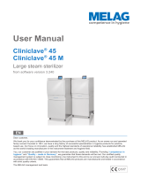
How does STATCLAVE G4 use a Venturi device to create a vacuum?
In the STATCLAVE G4, a water pump moves water through the constricted channel of a Venturi device. As the
water goes through this constriction, from a large pipe to a small pipe, it creates an area of low pressure. A
third tube connects to this constriction through which the low pressure draws a vacuum.

5
Diagram of key systems and components

6

7
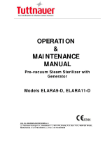
Front and back of the unit
1. Venturi reservoir drain quick-connect
(OUT)
2. Warm air exhaust
3. Clean water reservoir drain quick-connect
(OUT)
4. Clean water reservoir fill quick-connect
(IN)
5. Power switch
6. Bacteriological filter (bacteria-retentive air
filter)
7. Chamber rack
8. Touchscreen
9. USB port
10. Power cord input
11. Ethernet port (not visible)
12. Auto fill port for clean water reservoir
13. Condenser drain port (to drain for
shipping)
14. Overflow drain port for reservoirs
15. Exhaust drain port
16. RS232 port
17. Power port for external fill pump (option)

8
Top of the unit – inside reservoirs
1. Reservoir filters
2. Venturi reservoir temperature
sensor
3. Venturi reservoir level sensors (max.
and min.)
4. Venturi recirculation tap
5. Venturi reservoir
6. Water cooling recirculation tap
7. Clean water fill tap
8. Clean water reservoir
9. Clean water reservoir level sensors
(empty and full)
10. Clean water conductivity sensor

9
Specifications
Machine Dimensions:
Width: 17.75” / 450 mm
Height: 19-19.5” / 483-495 mm
Depth: 25” / 635mm
Chamber Dimensions:
Diameter: 11”/ 280 mm
Depth: 15”/381 mm
Sterilization Chamber Volume:
6.9 US gal / 26 L
Distilled Water Reservoir Volume:
1 US gal / 4 L
Venturi Reservoir Volume (including condenser):
1.6 US gal /6 L
Weight (without water):
136 lbs/ 61.7kg
Weight (with full reservoirs and full load):
175 lbs/ 79.5kg
Clearance required:
Top: 7” /180 mm
Right Side: 2” / 50 mm
Left Side: 0”/ 0 cm
Front with door open: 16”/ 41 cm
Water quality:
≤6.4ppm / 10 µS (conductivity at 20°C/68°F)
Minimum distilled water required for cycle:
0.26 US gal / 1 L
Minimum Venturi water required for cycle:
0.26 US gal / 1 L
PRV value (pressure relief valve):
Set at 40.6 PSI / 2.8 bar to release pressure in
overpressure situations
Electrical Rating*:
120V, 60Hz, 12 A
208-240V, 60Hz, 12A
*See serial number label for requirements specific to
your unit.
Ethernet Port:
10/100 Base-T
USB Port:
USB 2.0
Current:
AC
Protection Class:
I
Protection:
covered
Ambient Operating Temperature:
41˚F - 104˚F / 5˚C - 40˚C
Sound levels:
≤ 60 dB
Humidity:
80% maximum
Max. Altitude:
6,562 ft / 2000 m
Safety devices
• Overheat thermostat: Steam generator overheat thermostat’s set point 310°C.
• Overheat thermostat: Band heater overheat thermostat set point 180°C.
• Pressure relief valve: The chamber pressure relief valve is set to 40.6 PSI/ 2.8 bar gauge to release
pressure in an overpressure situation.
• Pressure or vacuum relief on power failure: The unit will automatically return the unit to atmospheric
pressure when the power is interrupted.
• Electrical protection: two 15 Amp fuses (high current) and 2 Amp fuse (low current).

10
Water supply
High quality distilled water is recommended for use in the STATCLAVE G4. Deionized, demineralized or
specially filtered water can also be used. Never use tap water. The STATCLAVE G4’s water conductivity sensor
automatically reads the water quality and will not allow the unit to run a cycle unless the water quality is ≤
6.4ppm / 10 µS (conductivity at 20˚C/ 68˚F).
Safety information
THE FOLLOWING TERMS APPEAR IN THIS SERVICE MANUAL
CAUTION!
A potential hazard to the operator or to patients.
IMPORTANT!
A situation that may affect the functioning of the unit or lead to a mechanical failure.
TIP
Additional information that may be helpful.
Pay close attention to the following symbols that appear on the unit:

11
Safe operation
The following apply to both operators and service technicians:
• Exercise caution and seek assistance when lifting or carrying the unit.
• Before performing routine maintenance or servicing the unit, turn the unit OFF and unplug the power
cord from the power source.
• The operator should never remove the cover of the unit or insert objects through holes or openings
in the cabinetry. Doing so may damage the unit and/or pose a hazard to the operator.
• If the unit is used in a manner other than that specified, the protection provided by the equipment
may be impaired.
Safe servicing
• SciCan shall not be liable for incidental, special or consequential damages caused by any maintenance
or services performed on the STATCLAVE G4 by a third party or for the use of equipment or parts
manufactured by a third party, including lost profits, any commercial loss, economic loss, or loss
arising from personal injury.
• All local, regional, state, and national regulations regarding the servicing of this class of device and
safety requirements must be observed.
When the panels are removed
• Hazardous voltages are accessible. Disconnect the power cord before removing any panels.
• Sharp metal edges are exposed. Be careful and wear long sleeves and gloves.
Electrical
• If the panels are removed, a dielectric strength test (Hi-Pot) AND a protective bonding impedance
test (ground continuity) must be performed on the STATCLAVE G4 when the work is completed and
after the panel has been reinstalled.
• The STATCLAVE G4 contains electronic circuitry that is static sensitive. Always wear a static strap
when working with or near printed wiring boards. In addition, use static footstraps, grounding mats
and grounded work surfaces when servicing microprocessor devices. Transport boards and devices
in static protected bags.
Lifting the unit
• The STATCLAVE G4 is heavy. Exercise caution and seek assistance when lifting or carrying the unit.
Water quality
• Use only steam-process distilled water in the STATCLAVE G4.
• Ensure that there is distilled water in the STATCLAVE G4 before activating the pump.

12
Reporting
• It is vital for SciCan to learn of any problem in the field. This information will help SciCan solve the
problem quickly and improve product reliability in new units.
Biological waste
• Waste water in the unit may contain biological contaminants; use a mechanical means to siphon the
contents. Wear disposable rubber gloves. Dispose of absorbent material according to biological
waste disposal regulations.
Tools and hardware
Tools required for servicing include:
• Needle-nose pliers
• Wrench
• Nut driver
• Hose clamp pliers
• Screwdriver Philips
• Wire stripper
• Screwdriver slot
• Spring clamp pliers
Electrical Safety test equipment:
• Hi-Pot tester
• Ground continuity tester
• Static strap
• Static bags
The unit contains the following types of hardware:
• Phillips pan head self-tapping metal screws
• Phillips pan head stainless steel machine screws
• Hex screws
• Spring clamps
• Metal cable ties
• Plastic cable ties

13
Shipping instructions
The unit should be serviced on site. If it is necessary to send the unit back to the dealer, follow these
instructions:
1. Drain water from the unit. Follow these steps:

14
2. Remove residual water from the water cooling system. Follow these steps:
a) Remove the Venturi water reservoir filter.
b) Insert siphoning tool into each drainage hole and pull residual water from the
system.
3. Screw in the leveling legs.
4. Specify upright, heated, and insured shipping.
5. Ensure unit is returned on a pallet with at least two banding straps securing the box to the pallet. If
original packaging is unavailable packaging can be ordered with part #01-115557S.
6. Shipping outside of these conditions can affect warranty.

15
2. LOCATION AND INSTALLATION
The STATCLAVE G4 will require a support surface that is strong enough to hold the weight of a fully loaded
unit with full reservoirs (a total operating weight of 175 lbs / 79.5 kg). The space should also allow room for
the door to open correctly, for the top reservoir lids to be opened for filling and for ventilation on the right
side. Please review the installation details outlined in the section below prior to installation.
If the STATCLAVE G4 is installed in a sterilization center, the manufacturer of the sterilization center should
allow enough space at the top, back and both sides of the unit to facilitate installation, leveling, and service
access to the unit.
During installation, all consumables should have been added to the machine as appropriate. It is important to
check that this has been undertaken before starting the machine.
Use the Installation Checklist for steps to ensure proper installation of unit.
Unboxing, connecting and lifting the unit into position
Remove the packaging’s plastic handle insets.
Slide the top cover up and off the unit.
Remove the accessories box and foam packaging.

16
Open the bag and, with one person on either side,
grip the strap handle and underside of the unit to
lift and remove it from the base packaging.
Unlatch the unit door to open it and remove items
stored in the chamber. Check the contents. (See
Checking package contents, in this section.)
With the unit still on the floor, connect the power
cord. (See Electrical connections and power, in this
section.)
Connect the exhaust tubes. (See Connecting the
exhaust tubes, in this section.)
Place the loose ends of the tubes and power cord
over the top of the unit.
With one person on either side, grip the strap
handle and underside of the unit to lift it into
position.
Once in position, push the power cord and hoses
through the cut-outs in the cabinetry to make the
connections.

17
Checking package contents

18
Positioning a unit
Unit dimensions and operating environment

19
Electrical connections and power
Electrical Connections
To power your unit, use properly grounded and fused power sources with the same voltage rating as
indicated on the serial number label at the back of your STATCLAVE G4.
•
DO use an outlet that is protected by a suitable breaker.
•
DO use a dedicated circuit, single phase 120 V~ 60Hz, 12A or 208-240 V~60Hz, 12A, depending
on the voltage rating indicated on the serial number label at the back of the unit.
Unit Electrical Characteristics:
•
Protection class 1 device.
• Maximum power consumption of the sterilizer is 1,440 Watts for 120V and 2,250-3,000 Watts
for 208-240V.
Connecting the exhaust tubes
IMPORTANT: For the unit to function, BOTH reservoirs must be full and BOTH drain tubes must be
connected.
The STATCLAVE G4 uses water from the Venturi reservoir to generate vacuum draws at the beginning
and end of each cycle. For the unit to operate, BOTH the clean water reservoir and the Venturi reservoir
must contain the minimum required water levels.
When the chamber releases steam it travels through the condenser and drains from the condenser
exhaust tube. Excess water in both the Venturi reservoir and the clean water reservoir drains from
the reservoir overflow tube. BOTH elbow fittings at the back of the unit must be connected to a water
draining system.

20
Direct to drain connection (recommended)
/