Whirlpool WFC8090GX Owner's manual

Type
Owner's manual

This manual is also suitable for

TECHNICAL EDUCATION
JOB AID W10329932
L-84
Vertical Modular
Washer
L-96
SERVICE MANUAL
WHIRLPOOL 2.8 CU FT SMART
ALL-IN-ONE WASHER & DRYER
W11243198
WFC8090GX
ii
n
Whirlpool Smart All-In-One Washer & Dryer
FORWARD
This Whirlpool Service Manual, (Part No. W11243198), provides the In-Home Service Professional with
service informaon for the “WHIRLPOOL 2.8 CU FT SMART ALL-IN-ONE WASHER & DRYER.
The Wiring Diagram used in this Service Manual is typical and should be used for training purposes
only. Always use the Wiring Diagram supplied with the product tech sheet when servicing the washer.
For specic operang and installaon informaon on the model being serviced, refer to the “Use and
Care Guide” or “Installaon Instrucons” provided with the washer.
GOALS AND OBJECTIVES
The goal of this Service Manual is to provide informaon that will enable the In-Home Service
Professional to properly diagnose malfuncons and repair the “WHIRLPOOL SMART ALL-IN-ONE
WASHER & DRYER.
The objecves of this Service Manual are to:
Understand and follow proper safety precauons.
Successfully troubleshoot and diagnose malfuncons.
Successfully perform necessary repairs.
Successfully return the washer to its proper operaonal status.
WHIRLPOOL CORPORATION assumes no responsibility for any repairs made on our
products by anyone other than authorized In-Home Service Professionals.
Copyright © 2018, Whirlpool Corporaon, Benton Harbor, MI 49022
Whirlpool Smart All-In-One Washer & Dryer
n
iii
TABLE OF CONTENTS
WHIRLPOOL SMART ALL-IN-ONE WASHER & DRYER
SECTION 1 — GENERAL INFORMATION
WASHER/DRYER SAFETY ....................................................................................................................1-2
INTRODUCTION ..................................................................................................................................1-3
CONTROL PANEL AND FEATURES .......................................................................................................1-4
CONTROL PANEL - TOOLS ...................................................................................................................1-5
LOAD & GO BULK DISPENSER .............................................................................................................1-5
THEORY OF OPERATION .....................................................................................................................1-6
PRODUCT SPECIFICATIONS ................................................................................................................1-7
WIRING DIAGRAM LOCATION ............................................................................................................1-8
MODEL AND SERIAL NUMBER LOCATION ..........................................................................................1-8
MODEL AND SERIAL NUMBER NOMENCLATURE ..............................................................................1-9
ALL-IN-ONE WASHER/DRYER MAINTENANCE .................................................................................1-10
CLEANING THE DRAIN PUMP FILTER/DRAINING RESIDUAL WATER ...............................................1-12
HOW TO MANUALLY OPEN A LOCKED DOOR ..................................................................................1-13
SECTION 2 — DIAGNOSTICS & TROUBLESHOOTING
CONTROL PANEL .................................................................................................................................2-2
ABBREVIATIONS .................................................................................................................................2-3
DIAGNOSTIC GUIDE ............................................................................................................................2-3
SERVICE DIAGNOSTIC MODE .............................................................................................................2-3
ACTIVATING SERVICE DIAGNOSTIC MODE ........................................................................................2-3
SERVICE DIAGNOSTIC MODE TESTS ...................................................................................................2-3
FAULT/ERROR CODES..........................................................................................................................2-7
TROUBLESHOOTING GUIDE ...............................................................................................................2-9
SECTION 3 — COMPONENT TESTING
COMPONENT TESTING: SAFETY INFORMATION ................................................................................3-2
WIRING DIAGRAM ..............................................................................................................................3-3
COMPONENT TESTING .......................................................................................................................3-4
TEST #1: ACU POWER CHECK ..............................................................................................................3-4
APPLIANCE CONTROL UNIT & PINOUTS ............................................................................................3-5
TEST #2: HUMAN-MACHINE INTERFACE (HMI) ..................................................................................3-6
TEST #3: MOTOR CIRCUIT ...................................................................................................................3-7
TEST #4: DOOR LOCK SYSTEM ............................................................................................................3-8
TEST #5: INLET VALVE .........................................................................................................................3-9
TEST #6: PRESSURE SWITCH .............................................................................................................3-10
TEST #7: DRAIN/RECIRCULATION PUMP .......................................................................................... 3-11
TEST #8: WASH HEATING ELEMENT .................................................................................................. 3-12
TEST #9: WASH TEMPERATURE SENSOR ..........................................................................................3-13
TEST #10A: DISPENSER SENSING ......................................................................................................3-14
TEST #10B: DISPENSER METERING PUMPS ...................................................................................... 3-16
TEST #11: SUPPLY CONNECTIONS - US .............................................................................................3-17
TEST #11: SUPPLY CONNECTIONS - CAN ...........................................................................................3-18
TEST #12A: DRY HEATING ELEMENT ................................................................................................. 3-19
TEST #12B: DRY TEMPERATURE SENSOR (NTC)................................................................................3-20
TEST #13: DRY FAN MOTOR ..............................................................................................................3-21
Continued on next page . . .
iv
n
Whirlpool Smart All-In-One Washer & Dryer
PRODUCT SPECIFICATIONS & WARRANTY INFORMATION SOURCES (inside back cover)
WHIRLPOOL SMART ALL-IN-ONE WASHER & DRYER
SECTION 4 — COMPONENT ACCESS
REMOVING THE DOOR ASSEMBLY .....................................................................................................4-2
REMOVING THE TOP PANEL ...............................................................................................................4-3
REPLACING THE HUMAN-MACHINE INTERFACE ...............................................................................4-4
REMOVING THE FRONT PANEL & BULKHEAD ....................................................................................4-6
REMOVING THE REAR ACCESS PANEL ................................................................................................4-7
REMOVING THE INLET VALVE ASSEMBLY ..........................................................................................4-8
REMOVING THE PRESSURE SWITCH ..................................................................................................4-9
REMOVING THE METERING PUMPS ................................................................................................4-10
REMOVING THE DETERGENT DISPENSER ........................................................................................4-11
REMOVING THE DRYER HEATING CHANNEL ASSEMBLY .................................................................4-12
REMOVING THE CONDENSER DUCT ASSEMBLY ..............................................................................4-13
REMOVING THE RFI FILTER ..............................................................................................................4-14
REMOVING THE DOOR LOCK ASSEMBLY .........................................................................................4-15
REMOVING THE APPLIANCE CONTROL UNIT (ACU) ........................................................................4-16
REMOVING THE MOTOR CONTROL UNIT (MCU) .............................................................................4-17
REMOVING THE HEATER & THERMISTOR ........................................................................................4-18
REMOVING THE DRAIN & RECIRCULATION PUMPS ........................................................................4-19
REMOVING THE DIRECT DRIVE MOTOR ..........................................................................................4-20
REMOVING THE TUB ASSEMBLY ......................................................................................................4-22
SECTION 5 — CONNECTIVITY
SMART FEATURES ...............................................................................................................................5-2
INTERNET CONNECTIVITY GUIDE.......................................................................................................5-3
WPS CONNECTIVITY INSTRUCTIONS .................................................................................................5-4
SMART OPERATION ............................................................................................................................5-5
CONNECTIVITY TROUBLESHOOTING .................................................................................................5-6
TABLE OF CONTENTS (CONT.)
GENERAL INFORMATION
Whirlpool Smart All-In-One Washer & Dryer
n
1-1
Section 1:
General Information
This secon provides general safety, parts, and informaon for
the “Whirlpool Smart All-In-One Washer & Dryer.”
n Washer & Dryer Safety
n General Informaon
n Control Panel and Features
n Load & Go Bulk Dispenser
n Theory of Operaon
n Product Specicaons
n Wiring Diagram Locaon
n Model & Serial Number Locaon
n Model & Serial Number Nomenclature
n All-In-One Washer/Dryer Maintenance
n Cleaning the Drain Pump Filter/Draining Residual Water
n How to Manually Open a Locked Door
n Notes
1-2
n
Whirlpool Smart All-In-One Washer & Dryer
GENERAL INFORMATION
Washer & Dryer Safety
You can be killed or seriously injured if you don't immediately
You
can be killed or seriously injured if you don't
follow
All safety messages will tell you what the potential hazard is, tell you how to reduce the chance of injury, and tell you what can
happen if the instructions are not followed.
Your safety and the safety of others are very important.
We have provided many important safety messages in this manual and on your appliance. Always read and obey all safety
messages.
This is the safety alert symbol.
This symbol alerts you to potential hazards that can kill or hurt you and others.
All safety messages will follow the safety alert symbol and either the word “DANGER” or “WARNING.”
These words mean:
follow instructions.
instructions.
DANGER
WARNING
GENERAL INFORMATION
Whirlpool Smart All-In-One Washer & Dryer
n
1-3
General Information
INTRODUCTION
Reinvent your laundry roune with a washer and dryer in
one machine. Innovave features on the Smart All-In-One
Washer & Dryer help you do laundry in fewer steps. Compact
24” width and ventless, exible enough to virtually install
anywhere. Never switch clothes to a dryer again, plus skip
steps with innovave features like Load & Go™ dispenser and
Automac Lint removal.
Smart All-In-One Washer & Dryer
Features:
Load & Go™ Plus Dispenser: (see page 1-4)
Space-Saving Design:
Smart Appliance:
Smart Appliance with Remote Control
What/How Controls:
This washer/dryer has a unique user interface to help you
select the best wash cycle for your load. The “What to
Wash/How to Wash” layout guides you to the opmal cycle
in two easy steps:
What to Wash & How to Wash
Opons:
Soil Level Opon
The Soil Level opon allows you to select a Light, Normal,
or Heavy soil level seng. The recommended soil level
is preset for each cycle. Some preset soil levels can be
changed. For heavily soiled and sturdy fabrics, select the
Heavy soil level seng. For lightly soiled and delicate
fabrics, select the Light soil level seng. Lower soil level
sengs will help reduce tangling and wrinkling.
Extra Rinses Opon
The Extra Rinses opon provides one or more addional
rinses to the selected cycle. The extra rinses can be
canceled at any me by touching the “X” on the touch
screen to the right of the esmated me remaining.
Pre-Soak Opon
The Pre-Soak opon can be set either on or o. Pre-Soak
may be ended at any me by touching the “X” on the touch
screen to the right of the esmated me remaining.
TumbleFresh™ Opon:
The Tumble Fresh™ opon will periodically tumble the
load aer the end of the cycle for up to 12 hours. Touch
TUMBLE FRESH to acvate this opon. This opon is not
available when a drying mode is selected. Tumble Fresh™
may be ended at any me by touching the “X” on the touch
screen to the right of the esmated me remaining.
Wrinkle Shield™ Opon:
The Wrinkle Shield™ opon is only available when a drying
mode is selected, and will periodically tumble the load aer
the end of the cycle for up to 12 hours. Wrinkle Shield™
may be ended at any me by touching the “X” on the touch
screen to the right of the esmated me remaining.
Accessories:
Pedestal with Storage: WFP2411GX
Color-matched pedestals raise the washer/dryer to a more
comfortable working height.
1-4
n
Whirlpool Smart All-In-One Washer & Dryer
GENERAL INFORMATION
Control Panel and Features
5
OPERATING INSTRUCTIONS
Control Panel and Features
POWER BUTTON
Touch to power up the washer/dryer.
HOME BUTTON
Touch this button and the LCD screen will show the
home screen, where you can select your cycle, settings,
and options.
FAVORITES BUTTON
Stores and accesses your favorite cycles.
LCD SCREEN
Use this screen to select cycle, settings, options, etc.
REMOTE ENABLE BUTTON
Touch this button to be able to use the Whirlpool
app
to control the washer/dryer. Download the Whirlpool
app
and follow the instructions to connect your washer/dryer
to your home Wi-Fi network. You may also visit
www.whirlpool.com/connect. In Canada, visit
www.whirlpool.ca/en_CA and click on the Whirlpool
®
Connected Appliances link.
TOOLS BUTTON
Touch this button to access the tools screen. For more
information, see page 13.
START/PAUSE BUTTON
Touch to start, or touch to pause a cycle. When you start a
cycle, the door will lock, the washer/dryer will sense the load
size, and the wash or dry cycle will begin.
1
2
3
5
7
6
7
7
1 3
2
6
5
74
4
Temperature
WARM
Spin Speed
EXTRA FAST
Auto Dry
Dry
What to Wash
REGULAR
How to Wash
NORMAL
4:28
3:15
Dispenser 1
This dispenser holds 33.8 oz (1000 mL) of liquid HE
detergent for your main wash cycle, and automatically
dispenses liquid detergent at the optimum time in the cycle.
Dispenser 2
This dispenser holds 16.9 oz (500 mL) of liquid fabric
softener. It automatically dispenses liquid fabric softener
at the optimum time in the cycle. This dispenser may
instead be used as a second liquid HE detergent dispenser.
See Step 11 on page 13 for information.
IMPORTANT: Do not use chlorine bleach in this washer/dryer,
and do not use powdered detergent in the Load & Go
bulk
dispenser. Powdered detergent must be added to the drum prior
to adding laundry. See “Using the All-In-One Washer/Dryer.”
A
B
B
A
Load & Go
Bulk Dispenser
The Load & Go
bulk dispenser holds up to 33.8 oz. (1000 mL)
of liquid HE detergent (Dispenser 1) and 16.9 oz. (500 mL) of
liquid fabric softener or liquid HE deter
gent (Dispenser 2), enough
for multiple loads of laundry. It adds the appropriate quantity of
HE detergent and liquid fabric softener to the wash load at the
proper time. See “Using the Bulk Dispenser” for information on
using the dispenser.
A
B
GENERAL INFORMATION
Whirlpool Smart All-In-One Washer & Dryer
n
1-5
9
Using the Load & Go
Bulk Dispenser
Follow the steps below to  ll the Load & Go
bulk dispenser
when using the washer for the 
rst time, or when the low detergent
icon or low fabric softener icon on the display indicate that
the deter
gent or fabric softener level is running low.
1.
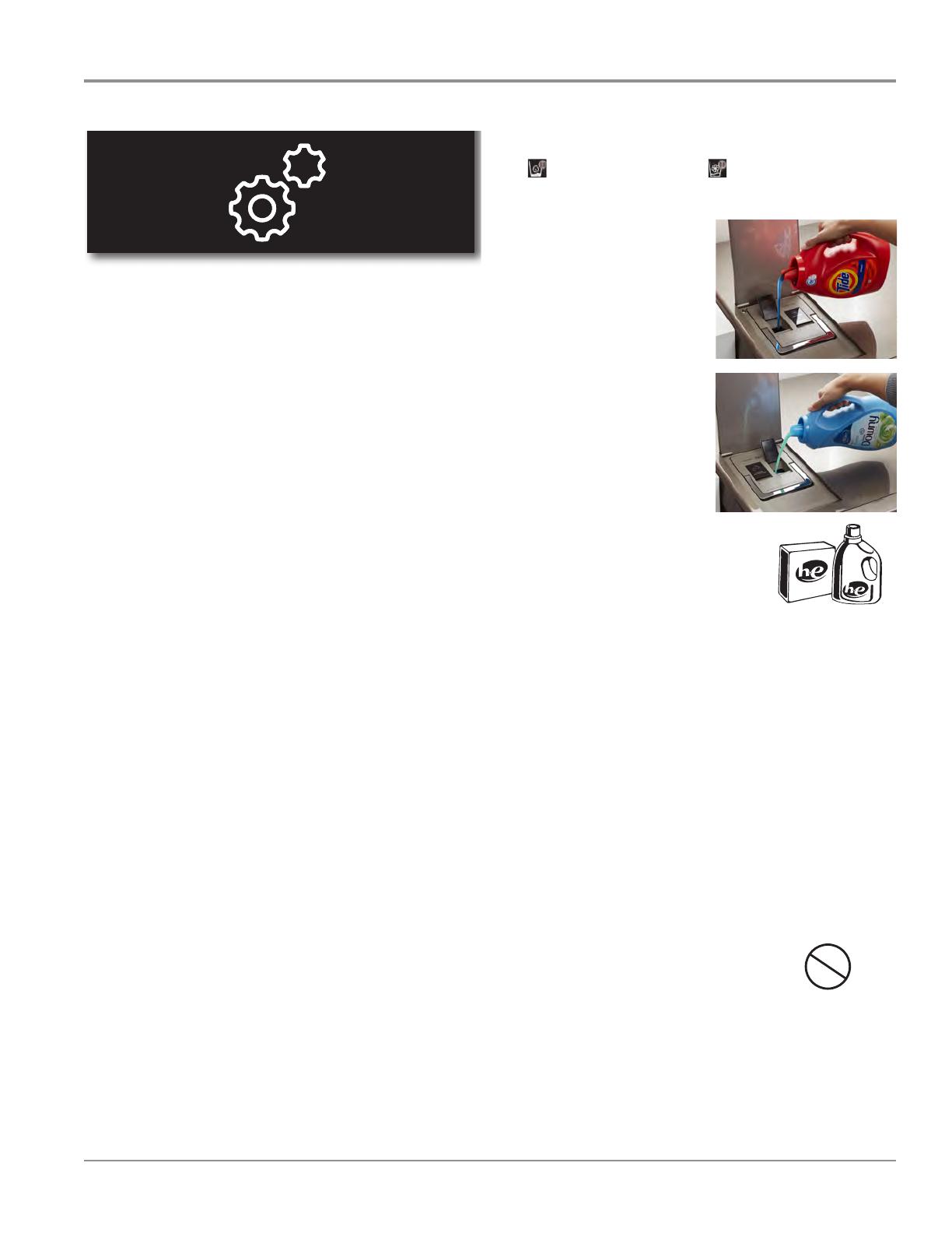
Open the bulk container lid on the top of the washer/dryer.
2.
Lift the  ll door on the
Liquid Detergent dispenser
(Dispenser 1). Add liquid HE
detergent up to the “MAX”
line. Do not over ll. Close the
ll door. It will click into place.
NOTE: If Dispenser 1 is empty,
you may choose to add only
enough liquid HE detergent
for one load.
3.
Lift the  ll door on the Liquid
Fabric Softener dispenser
(Dispenser 2). Add liquid fabric
softener up to the “MAX” line.
Do not over ll. Close the  ll
door. It will click into place.
NOTE: If Dispenser 2 is empty,
you may choose to add only
enough liquid fabric softener
for one load.
4.
Slowly close the bulk
container lid. Make sure
it is completely closed.
5.
Make sure that the bulk
dispenser is active. Use
the Tools button to make sure that
both Dispenser 1 and Dispenser 2
are active and that the detergent
concentration is correct. See
Step 11 on page 13.
NOTES:
Dispenser 2 may be used as a second Liquid HE Detergent
dispenser. Use the Tools button (go to “Load & Go
Dispenser
2”) to change the content in Dispenser 2 and set the deter
gent
concentration. Make sure that the other dispenser is disabled.
The entire Load & Go
bulk container can be easily removed
for ease of cleaning.
Thoroughly clean the Liquid Deter
gent dispenser (Dispenser 1)
before switching to a different brand of detergent.
Thoroughly clean the Liquid Fabric Softener dispenser
(Dispenser 2) before switching from liquid fabric softener
to liquid detergent, before switching back from liquid
detergent to liquid fabric softener, or before switching
to a different brand of detergent.
IMPOR
TANT:
Do not use chlorine bleach in this
washer/dryer. Chlorine bleach will
damage it.
Do not add a single-dose laundry packet to the bulk dispenser.
Do not use powdered HE detergent in the bulk dispenser.
Choosing the Right Detergent
Use only High Ef ciency detergents. The package will be marked
“HE” or “High Ef ciency.” Low-water washing creates excessive
sudsing with a non-HE detergent. Using non-HE detergent
will likely result in longer cycle times and reduced rinsing
performance. It may also result in component malfunction and,
over time, buildup of mold or mildew. HE detergents should be
low-sudsing and quick-dispersing to produce the right amount
of suds for the best performance. They should hold soil in
suspension so it is not redeposited onto clean clothes. Not all
detergents labeled as High Ef ciency are identical in formulation
and their ability to reduce suds. For example, natural, organic,
or homemade HE detergents may generate a high level of suds.
Always follow the detergent manufacturer’s instructions to
determine the amount of detergent to use.
Use only High Ef ciency
(HE) detergent.
About Detergent Concentration
Today’s liquid HE detergents are concentrated. Most brands of
concentrated HE detergent will show the level of concentration
on the bottle.
However, if the detergent bottle does not give the concentration,
it can be easily calculated. Just divide the package size in  uid
ounces by the number of loads. Then refer to the chart below
to  nd the concentration.
Set the concentration level setting on the washer by using
the Tools button (see Step 11 on page 13). If you do not get
your desired cleaning results, set the concentration level to a
lower concentration number. If you have excess suds, set the
concentration level to a higher concentration number.
Concentration Number of ounces ÷ number of loads
2X 1.5–2.49 (44.4 ml–73.6 ml)
3X 0.9–1.49 (26.6 ml–44.1 ml)
4X 0.7–0.89 (20.7 ml–26.3 ml)
5X 0.5–0.69 (14.8 ml–20.4 ml)
6X 0.3–0.49 (8.9 ml–14.5 ml)
Use only High Ef
ciency
(HE) detergent.
Chlorine
Bleach
Control Panel - Tools
13
12. Touch START/PAUSE button
to begin cycle
Touch the START/PAUSE button to start the cycle.
To pause a cycle in progress, touch the START/PAUSE button
once, then touch again to continue the cycle. To cancel a
cycle, touch the “X” on the touch screen to the right of the
estimated time remaining.
Once you touch the START/PAUSE button, you will hear
the door lock. The washer/dryer door will remain locked
during a wash cycle.
14. Remove garments promptly
after cycle is  nished
After a wash-only cycle, promptly remove
garments after cycle has completed to
avoid odor and rusting of metal objects on
garments. When unloading garments, pull
back the door seal and check for small items between the tub
and the washer/dryer drum.
If you will be unable to remove the load promptly after a wash-
only cycle, use the Tumble Fresh
option (see Step 10, page 12).
After a wash and dry cycle or a dry-only cycle, promptly
remove garments after cycle has completed to reduce wrinkling.
If you will be unable to remove a load promptly, use the Wrinkle
Shield
option (see Step 10, page 12).
NOTES:
The door will remain locked while the Tumble Fresh
option
is active after a wash-only cycle. To cancel the Tumble Fresh
option and unlock the door, touch the “X” on the touch
screen to the right of the estimated time remaining.
This washer/dryer has a tight seal to avoid water leaks.
To avoid odors, leave the door open to allow the washer/dryer
to dry between uses.
If a dry cycle is interrupted and the load removed before
the cool-down period at the end of the cycle, the load will
be very hot.
11. Use Tools button to change
other settings, if desired
The Tools button gives access to many other settings, utility
cycles, preferences, and information. Touch the TOOLS button
to access the Tools screen, which contains the following
(you will need to scroll down with your  nger to access
all of the selections).
Load & Go
Dispenser 1
Press this icon to access:
Load & Go
Status Dispenser 1 and choose between:
Active
Disabled (1 Cycle)
Off (Permanently)
Detergent Concentration Dispenser 1 and choose between:
2X
4X
6X
8X
Load & Go
Dispenser 2
Press this icon to access:
Load & Go
Status Dispenser 2 and choose between:
Active
Disabled (1 Cycle)
Off (Permanently)
Load & Go
Content Dispenser 2 and choose between:
Softener
Detergent
Once set at Detergent:
Set Concentration Dispenser 2 and choose between:
2X
4X
6X
8X
Control Lock
Press this icon to lock the controls. Swipe up to unlock.
Mute
Press this icon to mute or unmute sounds.
Utility Cycles
Press this icon to access the following utility cycles: Spin, Drain,
Rinse & Spin, and Clean Washer with affresh
®
cycle. Touch the
utility cycle you wish to use and follow the screen prompts.
Preferences
Press to access Times and Dates, Sound Volume, Display
Settings, and Regional. Follow the screen prompts.
WiFi
Press to access Connect to Network, SAID Codes,
Mac Address, and WiFi. Follow the screen prompts.
Info
Press to access Service & Support, Store Demo Mode,
Restore Factory, WiFi Terms and Conditions, and Software
Terms and Conditions. Follow the screen prompts.
13. Touch POWER button to turn off
washer/dryer after cycle ends
Tools
Load & Go Bulk Dispenser
1-6
n
Whirlpool Smart All-In-One Washer & Dryer
GENERAL INFORMATION
Theory of Operation
The illustraon below gives a brief descripon of the components involved specically on a Dry Cycle. Knowledge on the
system’s physical parts is needed in order to properly diagnose and troubleshoot the “all-in-one” washer/dryer.
1. Blower - Generates process air ow through the heater
channel, tub, and condenser duct.
2. Air Heater - Heats the air so it gets into the tub at high
temperature and reduced relave humidity.
3. Heater Channel - Conducts hot process air into the tub, so
it can remove humidity from the laundry.
4. Inlet Air NTC - Used as a feedback for the air heater
Control Soware.
5. Drain Pump - Pumps out condensed humidity and cooling
valve water that accumulates in the sump.
6. Sump NTC - Used as a feedback for the Auto-Dry Cycle
terminaon algorithms (apart from being used in heated
wash cycles).
7. Condenser Duct - Process air goes through condenser
duct to “get dry” - humidity is condensed and drained out
of the “all-in-one” washer/dryer.
8. Cooling Valve - Used to spray water into the condenser
duct, to cool down the process air and condense humidity.
Air Heater
Heater Channel
Blower
Inlet Air NTC
Drain Pump
Cooling Valve
Condenser Duct
Sump NTC
Dry Cycle - Illustraon
Figure 1 - Dry Cycle Theory of Operation
Dry Cycle - Theory of Operaon
GENERAL INFORMATION
Whirlpool Smart All-In-One Washer & Dryer
n
1-7
Product Specifications
UTILITIES
Line Voltage : 240 VAC
Frequency : 60 Hz
Amps : 30A
Water Supply : 20-100 psi (137.9–689.6 kPa)
DETAILS
Capacity : WFC8090GX = 2.8 Cu Ft
Size : 24” Wide
Motor Drive Type : Direct Drive
Motor Horsepower : 1/2 HP
Interior Light : Yes
Drum Material : Stainless Steel
Control : Electronic - Digital Display
FEATURES
Automac Load Size Sensing : Yes
Dispense System : Detergent / Fabric Soener / Load & Go
Wash Cycles : Clean Washer with aresh, Drain
What to Wash - Regular, Colors, Whites, Towels, Delicates, Bulky Items
How to Wash - Normal, Cold Wash, Heavy Duty, Quick, Sanize, Rinse & Spin, Spin
Wash/Rinse Temperatures : (5) Cold, Cool, Extra Hot, Hot, Warm
Spin : 5 Speeds,
Maximum Speed - 1400
Dryer Cycles : (2) Automac Dry, Timed Dry
Automac Lint Removal : Yes
SMART Appliance : Yes
Remote Start : Yes
OPTIONS
Washer Opon Selecons : Cold Water Pre Wash for Stains
Extra Rinse
Tumble Fresh™
Wrinkle Shield™
DIMENSIONS
Depth : 28” (71 cm)
Height : 33.75” (85.8 cm)
Width : 24” (61 cm)
Net Weight : 200 lbs. (90.7 kg)
ACCESSORIES
Pedestal, 11.3” : WFP2411GX
1-8
n
Whirlpool Smart All-In-One Washer & Dryer
GENERAL INFORMATION
Wiring Diagram & Model/Serial Number Location
Model & Serial Number
Label Location
Wiring Diagram Location
(Access under top panel on
top of dispenser assembly)
M o d e l # W F W 5 0 9 0 G W 0
Serial # CF62510000
Figure - Wiring Diagram, Model/Serial Number Location
GENERAL INFORMATION
Whirlpool Smart All-In-One Washer & Dryer
n
1-9
MODEL NUMBER W F C 8090 G X 0
INTERNATIONAL SALES OR
MARKETING CHANNEL
BRAND
W = Whirlpool
ACCESS
F = Front Load
PRODUCT
C = Combo Washer/Dryer
FEATURE SET
8090 = 2.8 Cu Ft, 24”
YEAR OF INTRODUCTION
G = 2018
COLOR CODE
X = Cashmere
ENGINEERING CHANGE
0 = Basic Release; 1 = First Revision; 2 = Second Revision
Model & Serial Number Nomenclature
SERIAL NUMBER TF 8 25 10000
SOURCE PRODUCTION
TF = HEFEI, CHINA
YEAR OF PRODUCTION
8 = 2018, 9 = 2019
WEEK OF PRODUCTION
2 Digits that represent the week of the year
PRODUCT SEQUENCE NUMBER
5 Digits that represent the unique product number
1-10
n
Whirlpool Smart All-In-One Washer & Dryer
GENERAL INFORMATION
All-In-One Washer/Dryer Maintenance
Washer/Dryer Care
Recommendations to Help Keep Your Washer/
Dryer Clean and Performing at Its Best
1. Always use High Eciency (HE) detergents and follow the
HE detergent manufacturer’s instrucons regarding the
amount of HE detergent to use. Never use more than the
recommended amount because that may increase the
rate at which detergent and soil residue accumulate inside
your washer, which in turn may result in undesirable odor.
2. Use warm or hot water washes somemes (not
exclusively cold water washes), because they do a beer
job of controlling the rate at which soils and detergent
accumulate.
3. Always leave the washer door slightly ajar between uses
to help dry out the washer and avoid the buildup of odor-
causing residue.
4. Periodically clean residue from all interior surfaces of the
glass window. For beer care, wipe the enre inside of
the glass door with a damp cloth.
Cleaning Your Front-Loading Washer
Read these instrucons completely before beginning the
roune cleaning processes recommended below. This Washer
Maintenance Procedure should be performed, at a minimum,
once per month or every 30 wash cycles, whichever occurs
sooner, to control the rate at which soils and detergent may
otherwise accumulate in your washer.
Cleaning the Door Seal
1. Open the washer door and remove any clothing or items
from the washer.
2. Inspect the seal between the door opening and the drum
for stained areas or soil buildup. Pull back the seal to
inspect all areas under the seal and to check for foreign
objects.
3. If stained areas or soil buildup are found, wipe down
these areas of the seal using the following procedure:
When the cycle is complete, gently pull back the rubber
door seal and clean the enre surface with the textured
side of an aresh® Machine Cleaning Wipe.
Cleaning the Inside of the Washer
This washer has a special cycle that uses higher water volumes
in combinaon with aresh® Washer Cleaner to thoroughly
clean the inside of the washer.
NOTE: Read these instrucons completely before beginning
the cleaning process.
Begin procedure
Clean Washer with affresh® Cycle Procedure
(Recommended for Best Performance):
a. Open the washer door and remove any clothing or
items.
b. Use an aresh® Machine Cleaning Wipe or a so,
damp cloth or sponge to clean the inside door glass.
c. Add an aresh® Washer Cleaner tablet to the washer
drum.
d. Do not add the aresh® Washer Cleaner tablet to the
bulk dispenser.
e. Do not add any detergent or other chemical to the
washer when following this procedure.
f. Close the washer door.
g. Select the Clean Washer with aresh® cycle.
h. Select the TumbleFresh™ opon to help dry the washer
interior aer the cycle is complete.
NOTE: The washer remembers your last opon
selecon and will use it for future wash cycles unl you
deselect that opon.
i. Touch the START/PAUSE buon to begin the cycle.
The Clean Washer with aresh® cycle operaon is
described below.
Description of Clean Washer with affresh® Cycle Operation:
1. Do not run this cycle with a load. Doing so could damage
the items.
2. Aer the cycle is complete, leave the door open slightly
to allow for beer venlaon and drying of the washer
interior.
Cleaning the Load & Go™ Bulk Dispenser
Aer a period of using your washer/dryer, you may nd some
residue buildup in the Load & Go™ bulk dispenser. To remove
residue from the dispensers, li the handle on the dispenser
housing to remove it from the washer/dryer cabinet, then
rinse the two dispensers thoroughly with running water. Wipe
the outside dispenser surfaces with an aresh® Machine
Cleaning Wipe or a damp cloth and towel dry. Use an all-
purpose surface cleaner, if needed. Replace the dispenser in
the washer/dryer cabinet and make sure that it is seated.
IMPORTANT: Load & Go™ bulk dispenser is not dishwasher
safe.
Cleaning the Outside of the Washer/Dryer
Use an aresh® Machine Cleaning Wipe or a so, damp
cloth or sponge to wipe up any spills. Occasionally wipe the
outside of your washer/dryer to help keep it looking new. Use
an aresh® Machine Cleaning Wipe or mild soap and water.
IMPORTANT: To avoid damaging the washer/dryer nish, do
not use abrasive products.
GENERAL INFORMATION
Whirlpool Smart All-In-One Washer & Dryer
n
1-11
Clean Washer Cycle Reminder
The Clean Washer with aresh® message will ash at the end
of a wash cycle when the washer has run 30 wash cycles. This
is a reminder to run the Clean Washer with aresh® cycle.
If the Clean Washer with aresh® cycle is not run, the message
will stop ashing at the end of a wash cycle aer running
three more regular wash cycles. Aer 30 more wash cycles are
completed, the Clean Washer with aresh® message will again
ash at the end of a wash cycle as a reminder.
Removing the Load & Go Bulk
Dispenser
To remove:
1. Li the bulk dispenser lid on the top of the washer/dryer.
2. Li up on the bulk dispenser handle and pull straight up
and out of the washer/dryer.
To replace:
1. Place the bulk dispenser back into the bulk dispenser
cavity on the top of the washer/dryer and make sure that
it is seated.
2. Close the bulk dispenser lid.
All-In-One Washer/Dryer Maintenance (continued)
Water Inlet Hose
Replace inlet hose aer 5 years of use to reduce the risk of
hose failure. Periodically inspect and replace inlet hose if
bulges, kinks, cuts, wear, or leaks are found.
When replacing your inlet hose:
n Mark the date of replacement on the label with a
permanent marker.
n Check that the old washer is not stuck on the washer inlet valve.
n Use a new washer in the new inlet hose to ensure a proper seal.
Non-Use and Vacaon Care
If moving, or not using your washer/dryer for a period of me,
follow these steps:
1. Unplug or disconnect power to washer/dryer.
2. Turn o water supply to washer/dryer to avoid ooding
due to water pressure surges.
HELPFUL TIP: Aach a reminder note to the washer/dryer
to turn the water back on before washers next use.
3. Clean the bulk dispenser. See “Cleaning the Bulk
Dispenser.
Winter Storage Care
IMPORTANT: To avoid damage, install and store washer/dryer
where it will not freeze. Because some water may stay in
hoses, freezing can damage washer/dryer. If storing or moving
during freezing weather, winterize your washer/dryer.
To winterize washer/dryer:
1. Shut o water faucet, disconnect and drain water inlet
hose.
HELPFUL TIP: Aach a reminder note to the washer dryer
to turn the water back on before washers next use.
2. Remove drain pump lter.
3. Put 1 qt. (1 L) of R.V.-type anfreeze in drum and run
washer on Normal cycle for about 2 minutes to mix
anfreeze and remaining water.
4. Unplug washer/dryer or disconnect power.
1-12
n
Whirlpool Smart All-In-One Washer & Dryer
GENERAL INFORMATION
Cleaning the Drain Pump Filter/Draining Residual Water
16
3. Lay a cotton cloth beneath the drain pump  lter to absorb
any water still in it. Then remove the drain pump  lter by
turning it counterclockwise.
4. Remove large clumps of lint by hand from the  lter and
place lint in a suitable waste container. Remove remaining
residue from the  lter by rinsing with water.
5. Reinsert the drain pump  lter by turning it clockwise.
Make sure to turn it in as far as it will go, with the  lter
handle left in a vertical position.
CLEANING THE DRAIN PUMP FILTER/
DRAINING RESIDUAL WATER (cont.)
CLEANING THE DRAIN PUMP FILTER/
DRAINING RESIDUAL WATER
1.
Open the drain pump 
lter access door at the bottom right
corner at the front of the washer/dryer.
2.
Place a broad,  at container beneath the drain pump  lter
to collect the drain water. Pull out the black hose, remove
the plug, and drain the hose into the container. Empty
the container. Repeat this procedure if necessary until all
the water has drained. Make sure that the black hose is
completely dry.
NOTE: Perform the following procedure every 6 months.
Black hose
Cleaning the Drain Pump Filter/
Draining Residual Water
16
3. Lay a cotton cloth beneath the drain pump  lter to absorb
any water still in it. Then remove the drain pump  lter by
turning it counterclockwise.
4. Remove large clumps of lint by hand from the  lter and
place lint in a suitable waste container. Remove r
emaining
residue from the  lter by rinsing with water.
5. Reinsert the drain pump  lter by turning it clockwise.
Make sure to turn it in as far as it will go, with the  lter
handle left in a vertical position.
CLEANING THE DRAIN PUMP FILTER/
DRAINING RESIDUAL WATER (cont.)
CLEANING THE DRAIN PUMP FILTER/
DRAINING RESIDUAL WATER
1. Open the drain pump  lter access door at the bottom right
corner at the front of the washer/dryer.
2. Place a broad,  at container beneath the drain pump  lter
to collect the drain water. Pull out the black hose, remove
the plug, and drain the hose into the container. Empty
the container. Repeat this procedure if necessary until all
the water has drained. Make sure that the black hose is
completely dry.
NOTE: Perform the following procedure every 6 months.
Black hose
WARNING
Electrical Shock Hazard
Disconnect power before cleaning.
Replace all parts and panels before operating.
Failure to do so can result in death or electrical shock.
GENERAL INFORMATION
Whirlpool Smart All-In-One Washer & Dryer
n
1-13
How to Manually Open a Locked Door
How to Manually Open the Door
1. Open the drain pump lter access door at the boom
right corner at the front of the washer/dryer. With a
Phillips head screwdriver, loosen and remove the Phillips
head screw at the upper right poron of the access door
compartment. (See Figure 1.)
3$*(
FOR SERVICE TECHNICIAN’S USE ONLY
DO NOT REMOVE OR DESTROY
3. Access ACU and dry fan motor.
4. Visually check connections between ACU
and dry fan motor.
¾If visual check passes, go to step 5.
¾If visual check fails, reconnect dry fan
motor and repeat step 1.
5. Disconnect wire connection and measure
resistance between contacts of dry fan motor.
¾If resistance is 40–50 1, go to step 6.
¾If resistance is much less or much greater
than 40–50 1, replace the dry fan motor.
6. Remove dry heating duct assembly.
7. Confirm that the blower wheel is not
obstructed and turns freely.
¾If the blower wheel is obstructed, remove
debris and re-assemble to washer/dryer.
¾If the blower wheel is not obstructed but
does not turn freely, replace the dry fan
motor.
¾If the blower wheel turns freely, replace
the ACU.
MANUALLY UNLOCKING
THE DOOR LOCK SYSTEM
1. Open the drain pump filter access door
at the bottom right corner at the front of the
washer/dryer. With a Phillips head screwdriver,
loosen and remove the Phillips head screw
at the upper right portion of the access door
compartment.
2. Pull down on the plastic strap located
beneath the removed screw. The door can
now be opened.
3. Secure the plastic strap by replacing and
tightening the Phillips head screw removed in
Step 1 through the hole in the strap.
COMPONENT REMOVAL
NOTE: Instructions are provided only for
those components where removal is not
obvious.
Components accessible through top panel:
Dispensing System
Dry Heater
Dry NTC
Thermal Cut-Offs
Interference Filter
Water Level Sensor
Water Valve Assembly
Components accessible through back panel:
Drive Motor
Wash Heater/Temp Sensor Assembly
Components accessible through bottom
of washer/dryer:
Drain Pump
Appliance Control Unit (ACU)
Motor Control Unit (MCU)
Figure 1
2. Pull down on the plasc strap located beneath the
removed screw. The door can now be opened. (See Figure
2.)
3$*(
FOR SERVICE TECHNICIAN’S USE ONLY
DO NOT REMOVE OR DESTROY
3. Access ACU and dry fan motor.
4. Visually check connections between ACU
and dry fan motor.
¾If visual check passes, go to step 5.
¾If visual check fails, reconnect dry fan
motor and repeat step 1.
5. Disconnect wire connection and measure
resistance between contacts of dry fan motor.
¾If resistance is 40–50 1, go to step 6.
¾If resistance is much less or much greater
than 40–50 1, replace the dry fan motor.
6. Remove dry heating duct assembly.
7. Confirm that the blower wheel is not
obstructed and turns freely.
¾If the blower wheel is obstructed, remove
debris and re-assemble to washer/dryer.
¾If the blower wheel is not obstructed but
does not turn freely, replace the dry fan
motor.
¾If the blower wheel turns freely, replace
the ACU.
MANUALLY UNLOCKING
THE DOOR LOCK SYSTEM
1. Open the drain pump filter access door
at the bottom right corner at the front of the
washer/dryer. With a Phillips head screwdriver,
loosen and remove the Phillips head screw
at the upper right portion of the access door
compartment.
2. Pull down on the plastic strap located
beneath the removed screw. The door can
now be opened.
3. Secure the plastic strap by replacing and
tightening the Phillips head screw removed in
Step 1 through the hole in the strap.
COMPONENT REMOVAL
NOTE: Instructions are provided only for
those components where removal is not
obvious.
Components accessible through top panel:
Dispensing System
Dry Heater
Dry NTC
Thermal Cut-Offs
Interference Filter
Water Level Sensor
Water Valve Assembly
Components accessible through back panel:
Drive Motor
Wash Heater/Temp Sensor Assembly
Components accessible through bottom
of washer/dryer:
Drain Pump
Appliance Control Unit (ACU)
Motor Control Unit (MCU)
Figure 2
3. Secure the plasc strap by replacing and ghtening the
Phillips head screw removed in Step 1 through the hole in
the strap. (See Figure 3.)
3$*(
FOR SERVICE TECHNICIAN’S USE ONLY
DO NOT REMOVE OR DESTROY
3. Access ACU and dry fan motor.
4. Visually check connections between ACU
and dry fan motor.
¾If visual check passes, go to step 5.
¾If visual check fails, reconnect dry fan
motor and repeat step 1.
5. Disconnect wire connection and measure
resistance between contacts of dry fan motor.
¾If resistance is 40–50 1, go to step 6.
¾If resistance is much less or much greater
than 40–50 1, replace the dry fan motor.
6. Remove dry heating duct assembly.
7. Confirm that the blower wheel is not
obstructed and turns freely.
¾If the blower wheel is obstructed, remove
debris and re-assemble to washer/dryer.
¾If the blower wheel is not obstructed but
does not turn freely, replace the dry fan
motor.
¾If the blower wheel turns freely, replace
the ACU.
MANUALLY UNLOCKING
THE DOOR LOCK SYSTEM
1. Open the drain pump filter access door
at the bottom right corner at the front of the
washer/dryer. With a Phillips head screwdriver,
loosen and remove the Phillips head screw
at the upper right portion of the access door
compartment.
2. Pull down on the plastic strap located
beneath the removed screw. The door can
now be opened.
3. Secure the plastic strap by replacing and
tightening the Phillips head screw removed in
Step 1 through the hole in the strap.
COMPONENT REMOVAL
NOTE: Instructions are provided only for
those components where removal is not
obvious.
Components accessible through top panel:
Dispensing System
Dry Heater
Dry NTC
Thermal Cut-Offs
Interference Filter
Water Level Sensor
Water Valve Assembly
Components accessible through back panel:
Drive Motor
Wash Heater/Temp Sensor Assembly
Components accessible through bottom
of washer/dryer:
Drain Pump
Appliance Control Unit (ACU)
Motor Control Unit (MCU)
Figure 3
1-14
n
Whirlpool Smart All-In-One Washer & Dryer
GENERAL INFORMATION
Notes
DIAGNOSTICS & TROUBLESHOOTING
Whirlpool Smart All-In-One Washer & Dryer
n
2-1
Section 2:
Diagnostics &
Troubleshooting
This secon provides diagnosc, fault codes, and
troubleshoong informaon for the “Whirlpool Smart All-In-
One Washer & Dryer.”
n Control Panel
n Abbreviaons
n Diagnosc Guide
n Service Diagnosc Mode
n Acvang Service Diagnosc Mode
n Service Diagnosc Mode Test
n Fault/Error Codes
n Troubleshoong Guide
2-2
n
Whirlpool Smart All-In-One Washer & Dryer
DIAGNOSTICS & TROUBLESHOOTING
Figure 1 - Human Machine Interface (HMI)

For Service Technician Use Only
3$*(
FOR SERVICE TECHNICIAN’S USE ONLY
DO NOT REMOVE OR DESTROY
CONTROL PANEL (buttons to use when entering Service Diagnostic Mode and Tests)
1. P
ress and hold the POWER button until the display
tur
ns on. After approximately 1 minute, the display
will show the Home screen, as indicated above.
Figure 1 - User Interface
2. Press the HOME button, the FAVORITES button,
and the TOOLS button three times within 8 seconds
( ).
Make sure a tone sounds for each button press.
The WARNING DIAGNOSTIC MODE screen will
display. Touch ENTER to enter diagnostic mode.
Temperature
WARM
Spin Speed
EXTRA FAST
Auto Dry
Dry
What to Wash
REGULAR
How to Wash
NORMAL
4:28
3:15
Home screen
Home button Tools button
Favorites button
/// /// //
  • Page 1 1
  • Page 2 2
  • Page 3 3
  • Page 4 4
  • Page 5 5
  • Page 6 6
  • Page 7 7
  • Page 8 8
  • Page 9 9
  • Page 10 10
  • Page 11 11
  • Page 12 12
  • Page 13 13
  • Page 14 14
  • Page 15 15
  • Page 16 16
  • Page 17 17
  • Page 18 18
  • Page 19 19
  • Page 20 20
  • Page 21 21
  • Page 22 22
  • Page 23 23
  • Page 24 24
  • Page 25 25
  • Page 26 26
  • Page 27 27
  • Page 28 28
  • Page 29 29
  • Page 30 30
  • Page 31 31
  • Page 32 32
  • Page 33 33
  • Page 34 34
  • Page 35 35
  • Page 36 36
  • Page 37 37
  • Page 38 38
  • Page 39 39
  • Page 40 40
  • Page 41 41
  • Page 42 42
  • Page 43 43
  • Page 44 44
  • Page 45 45
  • Page 46 46
  • Page 47 47
  • Page 48 48
  • Page 49 49
  • Page 50 50
  • Page 51 51
  • Page 52 52
  • Page 53 53
  • Page 54 54
  • Page 55 55
  • Page 56 56
  • Page 57 57
  • Page 58 58
  • Page 59 59
  • Page 60 60
  • Page 61 61
  • Page 62 62
  • Page 63 63
  • Page 64 64
  • Page 65 65
  • Page 66 66
  • Page 67 67
  • Page 68 68
  • Page 69 69
  • Page 70 70
  • Page 71 71
  • Page 72 72
  • Page 73 73
  • Page 74 74
  • Page 75 75
  • Page 76 76
  • Page 77 77
  • Page 78 78
  • Page 79 79
  • Page 80 80
  • Page 81 81
  • Page 82 82

Whirlpool WFC8090GX Owner's manual

Type
Owner's manual
This manual is also suitable for

Ask a question and I''ll find the answer in the document

Finding information in a document is now easier with AI