Page is loading ...

Studer Innotec SA 2018 – V4.7.0
4O9C
Remote control and programming unit
RCC-02 and RCC-03 for the Xtender
User manual


Studer Innotec SA
RCC-02/-03
User manual V4.7.0 1
CONTENTS
1 Foreword ................................................................................................................................................ 5
1.1 Conventions ..................................................................................................................................................... 5
1.2 Product recycling ............................................................................................................................................ 5
1.3 EU declaration of conformity ........................................................................................................................ 6
1.4 Studer Innotec contact details ..................................................................................................................... 6
1.5 Your reseller’ contact details ........................................................................................................................ 6
2 Warnings and caution .......................................................................................................................... 7
2.1 Warranty ............................................................................................................................................................ 7
2.2 Limitation of responsability ............................................................................................................................ 7
2.3 Safety instructions ............................................................................................................................................ 7
2.4 Acceptance of the software licence and updates ................................................................................. 7
2.5 Compatibility .................................................................................................................................................... 8
2.6 Access code for extended functions .......................................................................................................... 8
3 Introduction ........................................................................................................................................... 9
3.1 Models concerned ......................................................................................................................................... 9
3.2 Controls and indicators .................................................................................................................................. 9
3.3 SD card .............................................................................................................................................................. 9
4 Connection .......................................................................................................................................... 10
4.1 Series connection .......................................................................................................................................... 10
4.1.1 RCC-02 .................................................................................................................................................... 11
4.1.2 RCC-03 .................................................................................................................................................... 11
4.1.3 Xtender XTH ............................................................................................................................................ 11
4.1.4 Xtender XTM ........................................................................................................................................... 11
4.1.5 Xtender XTS ............................................................................................................................................. 11
4.1.6 VarioString ............................................................................................................................................... 12
4.1.7 VarioTrack ............................................................................................................................................... 12
4.1.8 BSP ............................................................................................................................................................ 12
4.1.9 Xcom-232i ............................................................................................................................................... 12
5 Dimensions .......................................................................................................................................... 13
5.1 RCC-02 ............................................................................................................................................................ 13
5.2 RCC-03 ............................................................................................................................................................ 13
6 Configuration assistant ....................................................................................................................... 14
7 Basic displays ...................................................................................................................................... 14
8 Activating and deactivating the Xtender combi ........................................................................... 15
9 Quick setting of the maximum source AC current ......................................................................... 16
10 RCC remote control settings ............................................................................................................. 16
10.1 Language {5000} ........................................................................................................................................... 17
10.2 Other languages {5036} ............................................................................................................................... 17
10.3 Time {5001} and Date {5002} ....................................................................................................................... 17
10.4 User level {5012} ............................................................................................................................................. 17
10.5 Force remote control to user BASIC level {5019} ..................................................................................... 18
10.6 Data logger {5057} ........................................................................................................................................ 18
10.6.1 Data logger enabled {5101} ............................................................................................................... 18
10.6.2 Save today's datas {5059} ................................................................................................................... 18
10.7 Save and restore files {5013} ........................................................................................................................ 18
10.7.1 Save all files (system backup) {5041} ................................................................................................. 18
10.7.2 Restore all files (system recovery) {5068} ........................................................................................... 19
10.7.3 Apply configuration files (master file) {5070} .................................................................................... 19
10.7.4 Separator of the .csv files {5032} ......................................................................................................... 19
10.7.5 Advanced backup functions {5069} ................................................................................................. 19
10.8 INSTALLER– Modification of access levels of many parameters {5042}............................................... 20
10.8.1 INSTALLER - Change all parameters access level to: {5043} ......................................................... 20
10.8.2 INSTALLER - Restore default access level of all parameters {5044} .............................................. 20
10.9 Backlight {5007} ............................................................................................................................................. 20
10.9.1 Backlight mode {5093} ......................................................................................................................... 20
10.9.2 Backlight switch off after {5009} .......................................................................................................... 20
10.9.3 Red backlight flashing on Xtender off and faulty {5026} ............................................................... 20
10.10 Extended and special functions {5021} ................................................................................................. 21

Studer Innotec SA
RCC-02/-03
2 V4.7.0 User manual
10.10.1 Display contrast {5006} ......................................................................................................................... 21
10.10.2 Choice of standard display {5073} ..................................................................................................... 21
10.10.3 Come back to standard display after {5010} .................................................................................. 21
10.10.4 Visibility of the transitory messages {5011} ........................................................................................ 21
10.10.5 Acoustic alarm active {5027} .............................................................................................................. 21
10.10.6 Remote control acoustic alarm duration {5031} ............................................................................. 21
10.10.7 Switching ON and OFF of system on level "VIEW ONLY" {5056} .................................................... 21
11 Information on the operating mode of the installation .................................................................. 22
11.1 Display of the parallel and three-phase systems .................................................................................... 24
12 Messages and account of events .................................................................................................... 25
12.1 (000) Warning: Battery low .......................................................................................................................... 25
12.2 (003) AC-In synchronization in progress .................................................................................................... 25
12.3 (004) Warning: Input frequency AC-In wrong .......................................................................................... 26
12.4 (006) Warning: Input voltage AC-In too high ........................................................................................... 26
12.5 (007) Warning: Input voltage AC-In too low ............................................................................................ 26
12.6 (008) Halted: Inverter overload SC............................................................................................................. 26
12.7 (014) Halted: Over temperature EL ............................................................................................................ 26
12.8 (015) Halted: Inverter overload BL .............................................................................................................. 27
12.9 (016) Warning: Fan error detected ............................................................................................................ 27
12.10 (018) Warning: Excessive battery voltage ripple ................................................................................. 27
12.11 (019) Halted: Battery undervoltage ....................................................................................................... 27
12.12 (020) Halted: Battery overvoltage .......................................................................................................... 27
12.13 (021) Transfer not authorized as AC-Out current is higher than Input Limit {1107} ........................ 27
12.14 (022) Error: Voltage presence on AC-Out ............................................................................................ 28
12.15 (023) Halted: Phase not defined ............................................................................................................ 28
12.16 (024) Warning: Change the clock battery ........................................................................................... 28
12.17 (041) Error: Over temperature TR ............................................................................................................ 28
12.18 (042) Halted: Unauthorized energy source at the output ................................................................. 28
12.19 (058) Halted: Master synchronization missing ...................................................................................... 28
12.20 (059) Halted: Inverter overload HW ....................................................................................................... 28
12.21 (060) (061) Warning: Time security for auxiliary contacts ................................................................... 29
12.22 (062) Warning: Genset, no AC-In coming after AUX command ...................................................... 29
12.23 Stored events ............................................................................................................................................. 29
13 Data logging ....................................................................................................................................... 30
13.1 Functioning ..................................................................................................................................................... 30
13.2 Analysis and visualization of the data with the Xtender data analysis tool ....................................... 30
14 Xtender settings .................................................................................................................................. 31
14.1 General ........................................................................................................................................................... 31
14.2 Configuration on a system with several Xtenders ................................................................................... 31
14.3 Utilisation and access levels ........................................................................................................................ 31
14.4 Pre-defined functions of the auxiliary relays ............................................................................................ 31
14.5 Access to the parameters ........................................................................................................................... 32
14.5.1 Access to a parameter by its number............................................................................................... 32
14.5.2 Access to a parameter via the menu ............................................................................................... 32
14.6 INSTALLER - Utilisation and access levels ................................................................................................... 33
14.7 Basic settings {1100} ...................................................................................................................................... 33
14.7.1 Basic parameters set by means of the potentiomenter in the XTS {1551} .................................. 33
14.7.2 Maximum current of AC source (Input limit) {1107} ........................................................................ 34
14.7.3 Battery charge current {1138} ............................................................................................................. 34
14.7.4 Smart-Boost allowed {1126} ................................................................................................................. 35
14.7.5 Inverter allowed {1124} ......................................................................................................................... 35
14.7.6 Type of detection of the grid loss (AC-In) {1552} ............................................................................. 35
14.7.7 Standby level {1187} ............................................................................................................................. 36
14.7.8 Restore default settings {1395} ............................................................................................................ 36
14.7.9 INSTALLER - Restore factory settings {1287} ....................................................................................... 36
14.8 Battery management and cycle {1137} ................................................................................................... 37
14.8.1 Charger allowed {1125} ....................................................................................................................... 40
14.8.2 INSTALLER - Charger uses only power from AC-Out {1646} ........................................................... 40
14.8.3 Battery charge current {1138} ............................................................................................................. 40
14.8.4 Temperature compensation {1139} ................................................................................................... 40
14.8.5 Undervoltage {1568} ............................................................................................................................. 41

Studer Innotec SA
RCC-02/-03
User manual V4.7.0 3
14.8.6 Battery overvoltage level {1121} ........................................................................................................ 42
14.8.7 Restart voltage level after an battery overvoltage {1122} ............................................................ 42
14.8.8 Floating voltage {1140} ........................................................................................................................ 42
14.8.9 Force phase of floating {1467} ............................................................................................................ 42
14.8.10 New cycle menu {1141} ....................................................................................................................... 42
14.8.11 INSTALLER - Use dynamic compensation of battery level (new cycle) {1608} .......................... 43
14.8.12 Absorption phase {1451} ...................................................................................................................... 43
14.8.13 Equalization phase {1452} .................................................................................................................... 44
14.8.14 Reduced floating phase {1453} .......................................................................................................... 46
14.8.15 Periodic absorption phase {1454} ...................................................................................................... 47
14.9 Inverter {1186} ................................................................................................................................................ 47
14.9.1 Inverter allowed {1124} ......................................................................................................................... 47
14.9.2 AC-Output voltage {1286} ................................................................................................................... 48
14.9.3 AC voltage increase according to battery voltage {1548} .......................................................... 48
14.9.4 Max AC voltage increase with battery voltage {1560} .................................................................. 48
14.9.5 Inverter frequency {1112} ..................................................................................................................... 48
14.9.6 Inverter frequency increase when battery full {1536} .................................................................... 49
14.9.7 Inverter frequency increase according to battery voltage {1549} ............................................. 49
14.9.8 Max frequency increase {1546} .......................................................................................................... 50
14.9.9 Speed of voltage or frequency change in function of battery {1534} ....................................... 50
14.9.10 Standby and turn on {1420} ................................................................................................................. 50
14.9.11 Solsafe presence, Energy source at AC-Out side {1438} ............................................................... 51
14.10 AC-In and transfer {1197} ......................................................................................................................... 51
14.10.1 Transfer relay allowed {1128} ............................................................................................................... 51
14.10.2 Delay before closing transfer relay {1580} ........................................................................................ 51
14.10.3 Smart-Boost allowed {1126} ................................................................................................................. 51
14.10.4 INSTALLER - Limitation of the power Boost {1607} ............................................................................ 52
14.10.5 Maximum current of AC source (Input limit) {1107} ........................................................................ 52
14.10.6 Max input current modification {1471} .............................................................................................. 52
14.10.7 Overrun AC source current limit without opening the transfer relay (Input limit) {1436} ......... 53
14.10.8 Type of detection of the grid loss (AC-In) {1552} ............................................................................. 54
14.10.9 Tolerance on detection of AC-input loss (tolerant UPS mode) {1510} ........................................ 54
14.10.10 Input voltage giving an opening of the transfer relay with delay {1199} ................................... 54
14.10.11 Time delay before opening of transfer relay {1198} ....................................................................... 54
14.10.12 Input voltage giving an immediate opening of the transfer relay (UPS) {1200} ........................ 54
14.10.13 INSTALLER – Absolute max limit for input voltage {1432} ................................................................ 54
14.10.14 Delta frequency allowed above the standard input frequency {1505} ..................................... 55
14.10.15 Delta frequency allowed under the standard input frequency {1506} ...................................... 55
14.10.16 Duration with frequency error before opening the transfer {1507} ............................................. 55
14.10.17 AC-In current active filtering {1575} ................................................................................................... 55
14.10.18 INSTALLER - Use an energy quota on AC-input {1557}.................................................................... 55
14.10.19 INSTALLER - AC-In energy quota {1559} ............................................................................................. 55
14.11 Auxiliary contacts 1 and 2 {1201} {1310} ............................................................................................... 55
14.11.1 Operating mode {1202} {1311} ........................................................................................................... 56
14.11.2 Combination of the events for the auxiliary contact {1497} {1498} ............................................. 57
14.11.3 Temporal restrictions {1203} {1312} ..................................................................................................... 57
14.11.4 Contact active with a fixed time schedule {1269} {1378} ............................................................. 57
14.11.5 Contact active on event {1455} {1456} ............................................................................................. 58
14.11.6 Contact active according to battery voltage {1245} {1353}........................................................ 59
14.11.7 Contact active with inverter power or Smart-Boost {1257} {1366} ............................................... 60
14.11.8 INSTALLER - Contact active according to battery temperature {1503} {1504} ......................... 60
14.11.9 Contact active according to SOC {1501} {1502} (only with BSP) ................................................. 61
14.11.10 Security, maximum time of contact {1512} {1513} .......................................................................... 61
14.11.11 Maximum time of operation of contact {1514} {1515} ................................................................... 61
14.11.12 Reset all settings {1569} {1570} ............................................................................................................ 61
14.12 Auxiliary contacts 1 and 2 extended functions {1489} ....................................................................... 62
14.12.1 Generator startup.................................................................................................................................. 62
14.12.2 Generator control active {1491} ......................................................................................................... 62
14.12.3 Number of starting attempts {1493} ................................................................................................... 62
14.12.4 Starter pulse duration (with AUX2) {1492} ......................................................................................... 62
14.12.5 Time before a starter pulse {1494} ...................................................................................................... 62

Studer Innotec SA
RCC-02/-03
4 V4.7.0 User manual
14.12.6 Main contact hold/interrupt time {1574} .......................................................................................... 62
14.13 System {1101}.............................................................................................................................................. 63
14.13.1 Remote entry (Remote ON/OFF) {1537}............................................................................................ 63
14.13.2 Batteries priority as energy source {1296} ......................................................................................... 64
14.13.3 Battery priority voltage {1297} ............................................................................................................. 64
14.13.4 Buzzer alarm duration {1565} ............................................................................................................... 64
14.13.5 Auto restarts {1129}................................................................................................................................ 65
14.13.6 System earthing (Earth - Neutral) {1484} ........................................................................................... 66
14.13.7 INSTALLER – Watchdog control system {1628} and {1629} ............................................................. 66
14.13.8 INSTALLER – Parameters saved in flash memory {1550} .................................................................. 66
14.13.9 Reset of all the inverters {1468} ........................................................................................................... 66
14.14 Multi Xtender system {1282} ..................................................................................................................... 67
14.14.1 Integral mode {1283} ............................................................................................................................ 67
14.14.2 Multi inverters allowed {1461} .............................................................................................................. 67
14.14.3 Multi inverters independents. Need reset {1468} {1462} ................................................................. 67
14.14.4 Battery cycle synchronized by the master {1555} ........................................................................... 67
14.14.5 Allow slaves standby in multi-Xtender system {1547} ...................................................................... 67
14.14.6 Splitphase: L2 with 180 degrees phaseshift {1571} .......................................................................... 67
14.14.7 INSTALLER – Minigrid compatible {1437} ............................................................................................ 67
14.14.8 INSTALLER – Minigrid with shared battery energy {1577} ................................................................ 68
14.15 Grid-feeding {1522} ................................................................................................................................... 68
14.15.1 Grid feeding allowed {1127} ............................................................................................................... 68
14.15.2 Maximum grid feeding current {1523} ............................................................................................... 68
14.15.3 Forced grid feeding {1524} {1525} {1526} .......................................................................................... 69
14.15.4 INSTALLER - Use of the defined phase shift curve for injection {1610} ......................................... 69
14.15.5 INSTALLER - Cos phi at P=0% {1622} .................................................................................................... 70
14.15.6 INSTALLER - Power of the second cos phi point in % of Pnom {1613} .......................................... 70
14.15.7 INSTALLER - Cos phi at the power defined by param {1613}, {1623} ........................................... 70
14.15.8 INSTALLER - Cos phi at P=100% {1624} ................................................................................................ 70
14.15.9 INSTALLER - ARN4105 frequency control enabled {1627} .............................................................. 70
14.15.10 INSTALLER - Delta from user frequency to start derating {1630} ................................................... 70
14.15.11 INSTALLER - Delta from user frequency to reach 100% derating {1631} ...................................... 70
15 Information on the system ................................................................................................................. 71
15.1 Remote controls ............................................................................................................................................ 71
15.2 Xtender ............................................................................................................................................................ 71
15.3 VarioTrack ....................................................................................................................................................... 71
15.4 VarioString ....................................................................................................................................................... 71
15.5 Accessoires ..................................................................................................................................................... 71
15.5.1 BSP (Battery Status Processor) ............................................................................................................. 71
15.5.2 Xcom-CAN .............................................................................................................................................. 71
16 Software updates ................................................................................................................................ 72
16.1 Updating process .......................................................................................................................................... 72
17 Application examples ....................................................................................................................... 73
17.1 General use: Inverter, Charger with grid .................................................................................................. 73
17.2 Use of a limited power source .................................................................................................................... 73
17.3 Use to increase the power on an existing installation ............................................................................ 74
17.4 Load shedding of the second priority loads ............................................................................................ 74
18 Appendices ......................................................................................................................................... 75
18.1 Appendix 1: List of configuration interdependencies ............................................................................ 75
18.2 Trouble-shooting ............................................................................................................................................ 76
19 Parameter tables ................................................................................................................................ 80
19.1 Remote control parameters ........................................................................................................................ 80
19.2 Inverter parameters ...................................................................................................................................... 82
20 Parameter index {xxxx} ..................................................................................................................... 94

Studer Innotec SA
RCC-02/-03
User manual V4.7.0 5
1 FOREWORD
This manual contains information relating to the functioning of the RCC-02 and RCC-03 remote
controls.
The use of certain functions sometimes requires advanced knowledge in various fields. This manual
cannot provide this. In case of doubt, please contact your reseller or installer.
1.1 CONVENTIONS
This symbol is used to indicate the presence of a dangerous voltage that is sufficient to
constitute a risk of electric shock.
This symbol is used to indicate a risk of material damage.
This symbol is used to indicate information that is important or which serves to optimize
your system.
Terminology:
The following terms are used in the manual to provide greater clarity:
RCC is used to indicate the remote control RCC-02 or RCC-03 if the description applies to both
models.
Installation is used to describe all the electrical equipment connected together. This may be the
source (public grid or generator), and one or more Xtender(s) with or without remote control as well
as electrical consumers.
System is used to describe the entirety of Xtenders with or without remote control.
Xtender or combi is used to describe one or more Xtender(s) connected together.
1.2 PRODUCT RECYCLING
The RCC remote control conforms to the European directive 2011/65/EU on hazardous substances
and does not contain the following elements: lead, cadmium, mercury, hexavalent chrome, PBB or
PBDE.
To dispose of this product, please use the service for the collection of electrical waste and observe
all applicable obligations according to the place of purchase.

Studer Innotec SA
RCC-02/-03
6 V4.7.0 User manual
1.3 EU DECLARATION OF CONFORMITY
The remote control, RCC-02/-03, described in this manual meets the requirements specified in the
following EC directives and norms:
Low Voltage Directive (LVD) 2014/35/EU
- EN 62368-1:2014
Electromagnetic Compliance (EMC) Directive 2014/30/EU
- EN 61000-6-2:2005
- EN 61000-6-4:2007/A1:2011
1.4 STUDER INNOTEC CONTACT DETAILS
Studer Innotec SA
Rue des Casernes 57
CH – 1950 Sion
Tel.: +41 (0)27 205 60 80
Fax.: +41 (0)27 205 60 88
Customer service: info@studer-innotec.com
Technical support: support@studer-innotec.com
Website: www.studer-innotec.com
1.5 YOUR RESELLER’ CONTACT DETAILS

Studer Innotec SA
RCC-02/-03
User manual V4.7.0 7
2 WARNINGS AND CAUTION
2.1 WARRANTY
Studer Innotec warrants its full range of inverters to be free from defects in workmanship and materials
for a period of 5 years from the date of manufacture.
Any warranty claim will be refused if it is not sent back to the point of sale, or another place indicated
by Studer Innotec, in appropriate packaging and accompanied by a copy of the dated proof of
purchase.
No warranty claims will be accepted for damage resulting from handling, usage or processing that
does not explicitly appear in this manual.
Cases of damage arising from the following causes are notably excluded from the warranty:
Inappropriate use
The presence of liquids in the device or oxidation resulting from condensation
Damage resulting from falls or mechanical shocks
The opening or alteration of the RCC remote control, carried out without the explicit
authorization of Studer Innotec
Damage due to atmospheric surge voltage (lightning)
Damage from transportation due to inappropriate packaging
2.2 LIMITATION OF RESPONSABILITY
The placement, commissioning, use, maintenance and servicing of the RCC remote control cannot
be the subject of monitoring by Studer Innotec. For this reasons Studer Innotec assumes no
responsibility and liability for damage, costs or losses resulting from an installation that does not
conform to the instructions, from a defective functioning or from a deficient maintenance.
The use of Studer Innotec devices is the responsibility of the customer in all cases. This equipment is
neither designed nor guaranteed to supply installations used for vital medical care nor any other
critical installation carrying significant potential damage risks to people or the environment.
Studer Innotec does not assume any responsibility for the infringement of patent rights or other rights
of third parties that result from using the devices.
The responsibility of Studer Innotec may not under any circumstances exceed the amount spent to
purchase the product.
Studer Innotec reserves the right to make any modifications to the product without prior notification.
2.3 SAFETY INSTRUCTIONS
Carefully read the following safety instructions in order to avoid any injury or risk of damaging this
product and those that are connected to it.
Only use the connection cable specified and supplied by Studer Innotec. Under no circumstances
should you use a damaged cable. In case of doubt about the condition of this device, it should be
inspected by a qualified technician.
Do not use the RCC remote control in a humid environment.
Do not use the RCC remote control in an explosive environment.
2.4 ACCEPTANCE OF THE SOFTWARE LICENCE AND UPDATES
By using the RCC remote control, you are accepting the terms and conditions of the following
licence agreement. Please read this carefully.
Studer Innotec is granting a limited licence to use the software installed in this equipment in its
executable binary format during the normal functioning of the product. The title, the property rights
and the copyrights relating to this software, remain the property of Studer Innotec.
You acknowledge that the software is the property of Studer Innotec and that it is protected by
copyright law according to the international copyright treaties.

Studer Innotec SA
RCC-02/-03
8 V4.7.0 User manual
You also acknowledge that the structure, organisation and software code are valuable commercial
secrets belonging to Studer Innotec. You agree not to decompile, disassemble, alter or reverse either
the unit or the engineering or make the software readable, irrespective of which part of the software,
or to create any work whatever that is based on this software.
Updating must be done in the full awareness of the cause and is always the responsibility of the
customer. Partial updates may cause ruptures in the compatibility or in its stochastic operation.
2.5 COMPATIBILITY
Studer Innotec guarantees the compatibility of the software updates with the hardware for one year,
starting from the date of purchase. The updates are no longer guaranteed beyond this date and a
hardware upgrade may be required. Please contact your reseller for any additional information on
compatibility.
2.6 ACCESS CODE FOR EXTENDED FUNCTIONS
In order to use the RCC-02, RCC-03 remote control in extended mode, you must have installer or QSP
(Qualified Service Partner) level authorisation from Studer Innotec. After your accreditation you will
receive a code number which will allow you to access these functions. This code number is
exclusively valid for devices manufactured during the current year or older; the most recent code
may therefore be used for all operations.
Fill in the code you have received below in order to take advantage of the extended functions of
the RCC-02, RCC-03 remote control.
Year
Code
2011-
The additional functions available with a professional user level appear in gray in this manual.
Depending on your access code, you may not have access to all the functions described in this
manual. Certain functions are reserved for servicing or factory testing. Please ask your supplier for
more details on this subject.

Studer Innotec SA
RCC-02/-03
User manual V4.7.0 9
3 INTRODUCTION
Congratulations! The purchase of an RCC remote control offers you unlimited access to the various
functions of the devices in the Xtender series. Numerous configurations that can now be accessed
allow you to optimize the operation of the installation. Despite all these options, the Xtender works
on a simple basis.
Different figure scenarios as well as associated configurations are presented at the end of this manual.
The manual for the RCC remote control is divided into several distinct parts:
The first part (page 10 to 21) is dedicated to the adjustments of the RCC remote control, whether this
is the language used or the clock, which are sometimes necessary for the whole installation to work
well.
The second part (page 22 to 29) is concerned with immediate information on the installation. This
gives access to the electric values such as the battery voltage, inverter load and many more.
The third part (page 30 to 30) shows the functions for saving events occurring in the installation. This
may be necessary for diagnosing a weakness or simply to check that the whole unit is working well
during its whole service life.
The fourth part (page 31 to 69), which is more technical, presents various options for configuring the
Xtender.
Do not change the configurations except when you have the technical knowledge; otherwise, the
operation of the installation could at risk or installation itself could be partly damaged.
The fifth part (page 71 to 74) consists of more general items like information about the system, the
updating process or examples of applications.
The sixth part (page 80 to 93) consists of two tables with all "Remote control" and "Inverter"
parameters. These tables, which follow the same hierarchical order as in the remote control, give an
overview on all adjustable parameters and also information about the factory settings.
3.1 MODELS CONCERNED
The RCC remote control may be connected to any Xtender, VarioTrack or VarioString the use of
which is clearly detailed in its operating instructions.
3.2 CONTROLS AND INDICATORS
The RCC remote control is equipped with four operating keys as well as a graphic display with
back-lighting. The function of the keys may change according to the context of utilisation and
a reminder of the function in progress is given at the right of the display.
Generally the keys UP and DOWN are used to alter values or options relating to what is on the
display and the two central keys are used to access, confirm or quit the item shown.
If the back-lighting function is activated, pressing one of the keys starts it up.
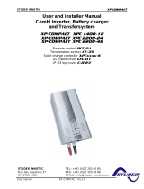
3.3 SD CARD
The RCC remote control is equipped with an SD (Secure Digital)-type memory
card reader. This card (supplied) is used for various functions described in this
manual. It allows, amongst others, the following
functions: recording statistics, updates, backups
or restoration of configurations or adjustments.
The filing system used for the data is the FAT
system (FAT16). This card can be read using any
standard SD card reader.
As far as the RCC-03 is concerned, the use of the
SD card requires removing the remote control
since the access to the SD lies behind.
The system of the card reading is compatible with the following types of cards: SD and SD HC
The system of the card reading is incompatible with the following types of cards: SD XC
and cards of more than 32 GB
RCC-02
RCC-03

Studer Innotec SA
RCC-02/-03
10 V4.7.0 User manual
4 CONNECTION
The RCC-02 remote control must be firmly fastened using 3 screws on a flat support. The remote
control RCC-03 is meant to be integrated. It must be mounted by means of 4 screws (not supplied)
on a flat surface without any mechanical constraints to the front plate. Once the RCC remote control
is fastened it can be connected to the inverter using the authorized cable only. If the cable is
damaged or if a socket is detached, the cable must not be connected since this can lead the whole
installation to malfunction.
A maximum of 3 remote controls can be connected to one unit. The XTS inverter/charger can only
be connected to one accessory.
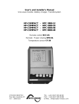
4.1 SERIES CONNECTION
Devices in the Xtender series are equipped with a proprietary communication bus for data
exchange, configuration and updating of the system. Series connection is obtained by linking the
devices with the provided communication cables. This way a serial bus is created where the
terminations must be activated on the units on both ends.
Each device is equipped with a switch offering to choose between open "O" and terminated "T". By
default, all terminations are activated on each Studer Innotec product. The devices at the end of
the line must be set on "T" (one cable) and all the others on "O" (two cables).
A wrong setting of the terminations can lead to an erratic running of the installation or
impede its updating.
The remote control must never be placed in between two devices connected to the
battery (Xtender, VarioTrack, VarioString).
Exemple of an installation with indicated terminations.

Studer Innotec SA
RCC-02/-03
User manual V4.7.0 11
4.1.1 RCC-02
RCC-02 termination activated (position T)
RCC-02 termination deactivated (position O)
4.1.2 RCC-03
RCC-03 termination activated
(left position)
RCC-03 termination deactivated
(right position)
4.1.3 Xtender XTH
To activate the termination on the Xtender, move the two mini-switches to position T, and to
deactivate it, move them downwards to position O.
4.1.4 Xtender XTM
On an Xtender type XTM, to activate the termination, put the mini-switch on position T, to deactivate
it, move it to the right on position O.
4.1.5 Xtender XTS
XTS termination activated (position T)
XTS termination deactivated (position O)

Studer Innotec SA
RCC-02/-03
12 V4.7.0 User manual
4.1.6 VarioString
VarioString termination activated (left position)
VarioString termination deactivated
(right position)
4.1.7 VarioTrack
VarioTrack termination activated (position T)
VarioTrack termination deactivated
(position O)
4.1.8 BSP
BSP termination activated (position T)
BSP termination deactivated (position O)
4.1.9 Xcom-232i
Xcom-232i termination activated (position T)
Xcom-232i termination deactivated (position O)


Studer Innotec SA
RCC-02/-03
14 V4.7.0 User manual
6 CONFIGURATION ASSISTANT
1 minute. Thanks to the Configuration Assistant, that’s all the time you will need to set-up a new
Xtender/Vario system. Using an RCC-02/-03 remote control, simply answer a few questions and all
Studer devices in the system will be configured to ensure optimum performance.
The new Configuration Assistant is available on all Studer Innotec RCC-02/-03 remote controls with
SW Release R640 or higher.
When the system is switched on, the Configuration Assistant
window will appear on the RCC-02/-03. If this is not the case and
you still want to use this function, press the down (↓) key repeatedly
until the “Configuration Assistant” window appears.
Press the SET key and follow the instructions displayed.
To configure and use more complex functions requires advanced technical knowledge. Please
contact your reseller or installer if you need assistance.
7 BASIC DISPLAYS
When the remote control is connected to an Xtender, it is possible to access to different display
menus divided into distinct categories.
Information on the system
The history of events occurring in the installation
Real time information displays on the operating mode of
the installation
The different measures carried out by the BSP or
Xcom-CAN
(Only if a BSP is present)
The different measures carried out by the VarioTrack
(Only if a VarioTrack MPPT is present)
The different measures carried out by the VarioString
(Only if a VarioString MPPT is present)
Information

Studer Innotec SA
RCC-02/-03
User manual V4.7.0 15
Configuration assistant for a quick and easy set-up
Adjustment of RCC remote control options
Adjustment of configurations on the Xtender(s)
The settings of the BSP
(Only if a BSP is present)
The settings of the Xcom-CAN
(Only if a Xcom-CAN is present)
The settings of the VarioTrack
(Only if a VarioTrack MPPT is present)
The settings of the VarioString
(Only if a VarioString MPPT is present)
To go from one display to the other, use the keys UP and DOWN on the RCC remote control.
To visualize or modify the options of one of the basic displays, press the key SET when this one is
displayed.
In the case of a system in 3-phase or in parallel, the following displays are available too:
Real time display of information on the state of running of
the installation
8 ACTIVATING AND DEACTIVATING THE XTENDER COMBI
When one of the displays is visible, it is possible to activate or deactivate the Xtender. To do this,
simply press the key ESC. The key request on the screen indicates whether you are going to activate
or deactivate the unit.
Depending on the components connected to your system, it is possible that other displays
complete this serie.
Settings

Studer Innotec SA
RCC-02/-03
16 V4.7.0 User manual
Once the key has been pressed, you must confirm your
choice by using the key YES. If you do not want the action
to be carried out, it can be cancelled by pressing the NO
key.
Note: This is a comprehensive signal and leads to the stoppage or starting of all Xtenders
connected to the remote control.
The Xtender can also be turned ON or OFF directly on the Xtender with
the button:
9 QUICK SETTING OF THE MAXIMUM SOURCE AC CURRENT
It is possible to access directly to the setting of the AC source maximum current (Input limit) {1107}
with the key SET (FAST) from the simplified display (clock).
For the users travelling, the available source often differs in power. This quick access menu
allows to easily set the maximum current available.
10 RCC REMOTE CONTROL SETTINGS
This screen gives you access to the remote control basic
settings. From one of the basic menu items, use the keys
UP and DOWN until reaching the item “Adjustment of the
remote control”, then confirm by using the key SET.
When the item to be modified appears on the screen, press the key SET to be able to
modify it. This value then displays in inverse video. Now use the keys UP and DOWN to
modify it. Once the correct value has been obtained, confirm by using the SET key or
exit without modifying by using the key ESC.
Each configuration has a unique ID displayed top right (see example below) these
numbers are indicated between curly brackets in this manual : {xxxx}
EXAMPLE to modify the current date
Go to the following screen using the UP and DOWN keys.
Press the key SET to access the remote control adjustment.
Go to the following screen using the key DOWN.
Press the key SET to modify the configuration
Set the correct date using the keys UP and DOWN
Go to the adjustment of the month using the key SET
Also set the month using the keys UP and DOWN
To complete, go to the year adjustment using the key SET
After having adjusted the year using the keys UP and
DOWN, confirm using the key SET.
/