Dometic AE Systems 3108706.015 Bottom Mounting Bracket Kit_Update Installation guide
- Type
- Installation guide

GENERAL INSTRUCTIONS
3108706.015 KIT, BOTTOM MOUNTING BRACKET (UPDATE)
KIT CONTAINS:
3104653.005 Bracket Assembly Bottom .....................2
830553.001 Patio Foot..............................................2
317534.006 1/4" - 20 Nut with Nylon Insert ..............2
113299 1/4" - 20 x 2-3/4" Slotted
Pan Head Screws .................................2
113075.002 #14 x 2-1/2" Hex Head
Sheet Metal Screws ..............................4
3104485.002 Spacer, Bottom Bracket ........................2ea.
QTY. TOOLS REQUIRED:
Electric Drill
Drill Bit 3/16"
Drill Bit 7/32"
Drill Bit 1/4"
Phillips Screwdriver
Socket Wrenches
This Kit is designed to fit the 5000, 8000, 8500, 9000 and
9500 awnings. It will update the bottom mounting bracket
and patio foot to the current style.
This Kit is designed to be used on straight sided
hardware only.
Read all instructions before beginning installation.
Instructions assume the awning is mounted on the
vehicle.
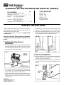
1. Bottom Mounting Bracket
Installation
A. Without opening awning, remove patio foot from Bottom
mounting bracket by pressing black tab on left side of
bracket and pulling straight out on arm assembly. Swing
away from bottom mounting bracket.
B. Remove existing bottom mounting bracket by taking out
two (2) #14 x 2-1/2" Hex Washer Head Sheet Metal
Screws securing bracket to vehicle. (FIG. 1)
C. Position new bottom spacer bracket in same location.
Using holes in new bracket as a guide, mark and drill
two (2) 3/16" holes in vehicle). (Use a 7/32" hole if going
through steel.)
D. If mounting on flat surface, use bottom bracket insert
between vehicle and bottom bracket. (FIGS. 2A & 2B).
E. Place the new bottom bracket on top of the spacer.
Secure both new brackets to vehicle with two (2) #14 x
2-1/2" Hex Washer Head Sheet Metal Screws.
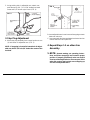
2. Patio Foot Installation
A. Assure travel lock pin is in place. Raise lift handle and
separate adjustable arm from main arm. Allow top of
main arm to rest on top bracket.
B. Remove existing patio foot by using a 1/4" drill bit to drill
out rivet which connects patio foot to adjustable arm.
(FIG. 3).
REVISION
Form No. 3104102.011 12/97
(Replaces 3104102.003)
©1997 The Dometic Corporation
LaGrange, IN 46761
FIG. 1
FIG. 2A FIG. 2B
FIG. 3
BOTTOM
BRACKET
SPACER

B. Insert adjustable arm in main arm until stop plug contacts
bottom of main arm.
C. Insert new patio foot into new bottom bracket so latch on
bracket catches rivet of patio fott.
4. Repeat Steps 1-3 on other Arm
Assembly.
5. NOTE: Operate awning per operating instruc-
tions and insure stop plugs are located in proper
position. If properly positioned, main arm should
clear top mounting bracket as it moves past. If the
main arm contacts top bracket, move stop plug up
one hole on adjustable arms.
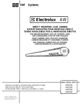
C. Using existing hole in adjustable arm, attach new
patio foot using 1/4" - 20 x 2-3/4" slotted pan head
screw and 1/4" nut with nylon insert. (FIG. 4)
3. Stop Plug Adjustment
A. Move stop plug assembly from current location to one
(1) hole lower on adjustable arm. (FIG. 5)
NOTE: If stop plug is located in lowest hole of adjust-
able arm, drill a 3/8" hole 3/4" below the center of the
last hole.
FIG. 4
FIG. 5
-
 1
1
-
 2
2


Dometic AE Systems 3108706.015 Bottom Mounting Bracket Kit_Update Installation guide
- Type
- Installation guide
Ask a question and I''ll find the answer in the document
Finding information in a document is now easier with AI
Related papers
-
Dometic Universal Series - Awning; HDWR: 8270000, 8271000, 8272000; FRTA: Sunchaser, 8300 Installation guide
-
-
-
-
-
-
-
-
-
Other documents
-
Carefree Travel'r Installation guide
-
 A&E Systems Electrolux AW Series Installation & Operating Instructions Manual
-
A&E Systems 5000 Replacement Instructions Manual
-
Carefree Eclipse User manual
-
-
-
-
-
-
