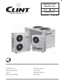
Clint CHA CLK 15÷81 CHA K 91÷151 User manual
- Category
- Heat pumps
- Type
- User manual

MANUALE DI
INSTALLAZIONE
USO E
MANUTENZIONE
INSTALLATION,
USE AND
MAINTENANCE
MANUAL
ITALIANO / ENGLISH
Serie / Series
Emissione / Issue Sostituisce / Replaces
Manuale / Manual
CHA/CLK 15÷81
CHA/K 91÷151
05.08
CLM 103.7 ab
04.07

2
CHA/CLK - CHA/K
CHA/CLK - CHA/K
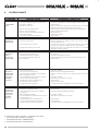
0. ELENCO DOCUMENTI ALLEGATI
Elenco documentazione fornita a corredo della mac chi na
facente parte integrante del presente manuale.
- Quaderno tecnico
- Manuale microprocessore
- Certi cato di garanzia
0. LIST OF ATTACHMENTS
List of documents supplied with the unit and forming
an integral part of this manual.
- Technical book
- Microprocessor manual
- Certi cate of guarantee

3
CHA/CLK - CHA/K
CHA/CLK - CHA/K
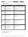
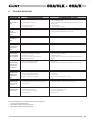
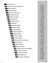
INDICE CONTENTS
Argomento
ELENCO DOCUMENTI ALLEGATI
PREMESSA
Informazioni generali
Allegati
Avvertenze
DESCRIZIONE DELLA MACCHINA
Identi cazione
Identi cazione della macchina
Destinazione d'uso
Controindicazioni
Descrizione generale
SICUREZZA
De nizioni
Regole generali di sicurezza
Simbologia
Mappa dei segnali di sicurezza
Segnali di sicurezza
Dispositivi di emergenza e di sicurezza
Descrizione del rischio residuo
Rischio residuo in prossimità della macchina
Misure da adottare in caso di fuoriuscita di
gas frigorigeno
Operazioni con rimozione dei pannelli
ISPEZIONE, TRASPORTO
Ispezione
Stoccaggio
Sollevamento e trasporto
Disimballo
INSTALLAZIONE
Scelta del luogo di installazione
Collegamento idraulico
Generalità
Subject
LIST OF ATTACHMENTS
INTRODUCTION
General information
Attachments
Warnings
UNIT DESCRIPTION
Identi cation
Identi cation
Intended use
Contraindications
General description
SAFETY
De nition
General safety regulations
Symbols
Location of safety signs
Safety signs
Emergency and safety devices
Description of residue risks
Residue risks near the unit
Measures to take in case of leaking refrige-
rant gas
Operations with the panels removed
INSPECTION AND TRANSPORT
Inspection
Storage
Lifting and transport
Unpacking
INSTALLATION
Choosing the installation site
Water connections
General
0
1
1.1
1.2
1.3
2
2.1
2.1.1
2.2
2.3
2.4
3
3.1
3.2
3.3
3.3.1
3.3.2
3.4
3.5
3.5.1
3.5.2
3.5.3
4
4.1
4.2
4.3
4.4
5
5.1
5.2
5.2.1
0
1
1.1
1.2
1.3
2
2.1
2.1.1
2.2
2.3
2.4
3
3.1
3.2
3.3
3.3.1
3.3.2
3.4
3.5
3.5.1
3.5.2
3.5.3
4
4.1
4.2
4.3
4.4
5
5.1
5.2
5.2.1

4
CHA/CLK - CHA/K
CHA/CLK - CHA/K
Evaporatore
Collegamenti elettrici
Generalità
Consensi esterni
AVVIAMENTO
Controlli pre li mi na ri all'avviamento
Messa in funzione
Veri che durante il funzionamento
Generalità
Sbrinamento
(Solo unità pompa di calore)
Arresto del gruppo
FUNZIONAMENTO
Generalità
Fermata stagionale
RICERCA GUASTI
MANUTENZIONE E CONTROLLI PE RIO DI CI
Avvertenze
Generalità
Controlli mensili
Controlli quadrimestrali
Riparazioni del circuito frigo
Rabbocchi di refrigerante
DISMISSIONE E SMALTIMENTO
5.2.2
5.3
5.3.1
5.3.2
6
6.1
6.2
6.3
6.3.1
6.3.2
6.4
7
7.1
7.2
8
9
9.1
9.1.1
9.1.2
9.2
9.3
10
Evaporator
Electrical connections
General
External signals
START UP
Preliminary controls
Start up
Checks during unit operation
General
Defrosting
(Only heat pump units)
Stopping the unit
OPERATION
General
Seasonal shut down
TROUBLE SHOOTING
ROUTINE MAINTENANCE AND CON-
TROLS
Warnings
General
Monthly controls
Four-monthly controls
Repairing the refrigerant circuit
Topping up the refrigerant liquid
SHUT DOWN AND DISPOSAL
5.2.2
5.3
5.3.1
5.3.2
6
6.1
6.2
6.3
6.3.1
6.3.2
6.4
7
7.1
7.2
8
9
9.1
9.1.1
9.1.2
9.2
9.3
10

5
CHA/CLK - CHA/K
CHA/CLK - CHA/K
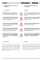
1. PREMESSA
1.1 INFORMAZIONI GENERALI
Questo manuale contiene le norme di installazione, uso e
manutenzione dei refrigeratori CHA/CLK - CHA/K, eviden-
ziandone ri schi e pericoli connessi. Esso è stato espressa-
mente studiato e sviluppato per permettere al personale
pre po sto un utilizzo facile e in sicurezza dei refrigeratori
d’ac qua CHA/CLK - CHA/K. Leggere attentamente e com-
pletamente tutte le informazioni in esso riportate. Prestare
par ti co la re at ten zio ne alle norme evidenziate con
in quanto se non osservate possono causare danno alle
persone, all’ambiente e/o alla macchina stessa.
La società declina ogni responsabilità per qual si a si uso
im pro prio della macchina, per mo di che alla stessa non
au to riz za te o per la non osservanza delle norme riportate
sul manuale. Il manuale deve essere conservato in luogo
sicuro e messo a disposizione del personale addetto alla
conduzione ed alla manutenzione del refrigeratore.
1.2 ALLEGATI
Fanno parte integrale del presente manuale i documenti
evidenziati a pag. 2.
1.3 AVVERTENZE
Le unità CHA/CLK - CHA/K sono state progettate e costruite
per ga ran ti re nel tempo grande a dabilità di esercizio e
massima sicurezza; per questo e grazie alle scelte progettuali
e realizzative, la società può ga ran ti re la totale con for mi tà
agli standard di sicurezza CE.
Ulteriore garanzia è assicurata dai collaudi cui la mac-
chi na è stata sottoposta in fabbrica.
All’utente resta quindi soltanto l’impegno di un uso
proprio e di una manutenzione preventiva conforme alle
in di ca zio ni contenute in questo manuale.
Ogni intervento, di qualsiasi natura, sulla
macchina deve essere preceduto da una
attenta lettura del presente manuale in tutte
le sue parti.
1. INTRODUCTION
1.1 GENERAL INFORMATION
This manual contains the installation, use and main te nance
instructions for the CHA/CLK - CHA/K chillers, and highlights
all connected risks and perils. It has been expressly pre pared
and written to allow authorised users to use the CHA/CLK
- CHA/K water chillers in complete safety and with the great-
est of ease. Please read the whole of this manual with care,
paying special attention to the sections marked with
as non-compliance may cause harm to people, de te ri o rate
the environment and/or damage the unit.
The company declines all responsibility for any improper
use of the unit, unauthorised modi cations or non-com-
pli ance with the instructions contained in this manual.
Please keep this manual in a safe place and make it
available to chiller operators and maintenance men.
1.2 ATTACHMENTS
The documents shown on page 2 form an integral part
of this manual.
1.3 WARNINGS
The CHA/CLK - CHA/K units have been designed and built to
ensure long-term operating reliability and maximum safety;
for this reason and thanks to the company’s design and
con struc tion policy, the company is able to guar an tee that
this product totally complies with EC safety stand ards.
A further guarantee of this is provided by the factory
tests carried out on the unit.
The user, therefore, must only ensure the unit is properly
used and that maintenance operations are carried out
according to the indications contained in this manual.
The unit should not be touched until the whole
of this manual has been carefully read.

6
CHA/CLK - CHA/K
CHA/CLK - CHA/K
Il manuale di installazione, uso e ma nu ten -
zio ne deve essere sempre a disposizione
degli addetti, i quali, prima di ogni ope ra zio ne
sulla macchina, devono ob bli ga to ria men te
leggerlo.
Per ogni ulteriore informazione e chiarimento la
G.I. HOLDING S.p.A. si rende disponibile al seguente
indirizzo:
G.I. HOLDING S.p.A.
Assistenza Clienti
Via Max Piccini , 11/13 - 33050 RIVIGNANO (UD)
ITALY
tel. +39 0432 773220
fax +39 0432 773855
e-mail: [email protected]
This installation, use and maintenance man-
u al must always be kept within easy reach
of authorised staff who are obliged to read
it before carrying out any operations on the
unit.
For any further information or explanations please con-
tact G.I. HOLDING S.p.A. at the following address:
G.I. HOLDING S.p.A.
Customer Service
Via Max Piccini , 11/13 - 33050 RIVIGNANO (UD)
ITALY
tel. +39 0432 773220
fax +39 0432 773855
e-mail: [email protected]

7
CHA/CLK - CHA/K
CHA/CLK - CHA/K
2 DESCRIZIONE DELLA MACCHINA
Questo capitolo ha lo scopo di fornire una descrizione
generale delle caratteristiche principali della macchina
nel suo insieme, unitamente a quella dei principali com-
po nen ti, standard e opzionali.
2.1 IDENTIFICAZIONE
2.1.1 Identifi cazione della macchina
La macchina si identi ca tramite le targhette poste sul
telaio e sul quadro elettrico. Le targhette riportano i
se guen ti dati:
- Ragione sociale del costruttore
- Indirizzo del costruttore
- Designazione della serie e del tipo di unità
- Numero di matricola
- Anno di costruzione
- Tipo e quantità di refrigerante
- Massima pressione ammissibile
- Taratura dei pressostati
- Simbolo della certi cazione CE
- Caratteristiche elettriche
- Identi cazione schema elettrico
2 UNIT DESCRIPTION
This chapter contains a general description of the main
unit characteristics, together with those of its principal
standard and optional components.
2.1 IDENTIFICATION
2.1.1 Unit identifi cation
The unit can be identi ed throug the plats attached on
the frame and in the electrical box. This label con tains
the fol low ing in for ma tion:
- Manufacturer’s name
- Manufacturer’s address
- Description of the series and type of unit
- Series number
- Year of construction
- Type and quantity of refrigerant liquid
- Max. Allowable pressure
- Pressure switch set point
- EC certi cation symbol
- Electrical characteristics
- Wiring diagram identi cation
G.I. HOLDING S.p.
A
Via Max Piccini, 11/13
33050 RIVIGNANO (UD) - ITALY
Manufactured by BV.ITA.40.02.1230
Modello/Model Matricola/Serial number
Modell/Modèle Matrikelnr/Matricule G.I. HOLDING S.p.A
Via Max Piccini 11/13
Tensioni-Fasi-Frequenza Tensioni circuiti ausiliari 33050 RIVIGNANO (UD)
Voltage-Phases-Frequency Auxiliary circuit voltage ITALY
Spannung-Phasen-Frequenz Hilfstromkreisspannung Tel. +39 0432 773220
Tension-Phases-Fréquence Tension circuits auxiliaires Fax. +39 0432 773855
V E-mail: [email protected]
Corrente massima assorbita Corrente massima di spunto Web: www.clint.it
Max absorbed current Max starting current Manufactured by BV.ITA.40.02.1230
Maximale Stromaufnahme Max Anlaufstrom DIRETTIVA 97/23/CE del 29 maggio 1997 (P.E.D.) cat I
Courant maxi absorbée Courant maxi de démarrage
AA
Modello/Model
Tipo di refrigerante Carica refrigerante per circuito
Modell/Modèle
Refrigerant type Refrigerant charge per circuit
Kältemittel Typ Kältemittelfüllung pro Kreislauf Matricola/Serial number
Type de réfrigerant Charge de réfrigerant chaque circuit Matrikelnr/Matricule
kg
Taratura pressostato di alta Press. massima circuito idraulico Anno di costruzione
High pressure switch setting Max hydraulic circuit pressure Construction year
HD-Wächter Einstellung Max. Druck im hydraul. Kreislauf Baujahr
Préssion maxi refrigerant Préssion maxi circuit hydraulique Année de fabrication
Bar Bar
Gruppo del fluido frigorifero Data di produzione PS Max.Press.ammissibile
Group of the refrigerant fluid Manufacturing date Max Working press.Refrig.side
Kältemittel Klasse Herstellungsdatum Max Betriebsdruck Kältemittelseitug
Groupe de fluide frigorifique Date de fabrication Press.max.de travail cute refrigerant
28 bar
20 bar
ALTA
HIGH PRESS.
HOCHDUCK
HAUTE
BASSA
LOW PRESS.
NIEDERDUCK
BASSE
28 bar
20 bar
ALTA
HIGH PRESS.
HOCHDUCK
HAUTE
BASSA
LOW PRESS.
NIEDERDUCK
BASSE
28 bar
20 bar
ALTA
HIGH PRESS.
HOCHDUCK
HAUTE
BASSA
LOW PRESS.
NIEDERDUCK
BASSE
28 bar
20 bar
ALTA
HIGH PRESS.
HOCHDUCK
HAUTE
BASSA
LOW PRESS.
NIEDERDUCK
BASSE
bar
bar
ALTA
HIGH PRESS.
HOCHDUCK
HAUTE
BASSA
LOW PRESS.
NIEDERDUCK
BASSE

8
CHA/CLK - CHA/K
CHA/CLK - CHA/K
2.2 DESTINAZIONE D’USO
I CHA/CLK - CHA/K sono refrigeratori con condensazione
ad aria de sti na ti a ra reddare acqua (eventualmente ad di -
zio na ta con glicole etilenico inibito) che circola in un anello
chiuso. Le unità a pompa di calore pos so no, a se con da
del ciclo di funzionamento scelto, ra red da re o ri scal da re
l’acqua dell’anello.
Il caldo, o il freddo, così prodotto può essere utilizzato per
impianti di climatizzazione o per processi industriali.
2.3 CONTROINDICAZIONI
Non impiegare in prossimità della macchina
prodotti infi ammabili.
Non impiegare in prossimità della macchi-
na sostanze in grado di formare miscele
esplo si ve.
Non impiegare la macchina dove sus si sto no
problemi di impatto ambientale (vedi pun to
3.5 pag. 13).
2.4 DESCRIZIONE GENERALE
Tutte le strutture sono realizzate in peraluman. La strut tu ra
è autoportante ed i pannelli sono facilmente rimovibili
in modo da permettere l’ac ces so all’interno della unità
per le operazioni di ma nu ten zio ne e riparazione.
3 SICUREZZA
3.1 DEFINIZIONI
In questo documento verranno utilizzate le seguenti
de ni zio ni:
- Zone pericolose: qualsiasi zona all’interno e/o in
pros si mi tà della macchina in cui la presenza di una
per so na esposta costituisca un rischio per la sicurezza
e la salute di detta persona.
- Persona esposta: qualsiasi persona che si trovi in ter -
na men te o in parte in una zona pericolosa.
- Operatore/Manutentore: la o le persone incaricate di
far funzionare, regolare, eseguire la manutenzione,
ri pa ra re, movimentare la macchina.
2.2 INTENDED USE
The CHA/CLK - CHA/K series of air condensation chillers have
been de signed to cool water (possibly containing inhibited
eth yl ene glycol) circulating in a closed circuit. The heat
pump units can cool or heat the water in the closed circuit
depending on which operating cycle is chosen.
The heat or cold produced can be used for air-con di -
tion ing systems or industrial processes.
2.3 CONTRAINDICATIONS
Do not use infl ammable products near the
unit.
Do not use substances that can form ex-
plo sive mixtures near the unit.
Do not use the unit in conditions that could
be harmful for the environment (see point
3.5 on page 13).
2.4 GENERAL DESCRIPTION
All the unit structures are made from peraluman. The
struc ture is free standing and the panels are easy to
remove in order to allow access to the inside of the unit
for main te nance and repair operations.
3 SAFETY
3.1 DEFINITION
This document uses the following de nitions:
- Dangerous areas: any area inside and/or near to the
unit in which the presence of a person would give rise
to a risk for that person’s health.
- Exposed person: anyone who is wholly or partly inside
a dangerous area.
- Operator/Maintenance man: person or persons au-
thor ised to operate, adjust, service, repair or move
the unit.

9
CHA/CLK - CHA/K
CHA/CLK - CHA/K
3.2 REGOLE GENERALI DI SICUREZZA
È vietato alle persone non autorizzate av vi -
ci nar si alla macchina.
Prima di ogni intervento di manutenzione
sulla macchina, seguire scrupolosamente
quanto indicato nel capitolo 9 a pag. 30.
È vietata la rimozione delle protezioni e l’esclusio-
ne dei dispositivi di sicurezza e di emergenza.
È vietato stazionare sulla macchina.
- Impiegare la macchina solo per l’uso a cui essa è
destinata.
- Il costruttore non risponde dei danni derivanti da un
impiego improprio della macchina o da modifiche
tec ni che e ettuate sulla macchina.
- Controllare regolarmente se i dispositivi di sicurezza
presentano un funzionamento corretto.
- Non smontare, modificare o mettere fuori funzione
parti della macchina.
- Per tutti gli interventi da e ettuare sulla macchina,
utilizzare esclusivamente attrezzi ed equipaggiamenti
idonei e in buone condizioni. Gli operatori dovranno
indossare i normali dispositivi di protezione individuali
(guanti, casco, occhiali, ecc.).
- I lavori sull’equipaggiamento elettrico devono essere
eseguiti solo da un elettricista quali cato.
- Gli interventi sul circuito frigorifero possono essere
e ettuati solo da personale specializzato.
3.3 SIMBOLOGIA
Veri care periodicamente lo stato delle targhette e prov-
ve de re, in caso di necessità, al loro ripristino.
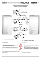
3.3.1 Mappa dei segnali di sicurezza
3.2 GENERAL SAFETY REGULATIONS
It is forbidden for unauthorised persons to
approach the unit.
Scrupulously observe the contents of chap-
ter 9 on page 30 before carrying out each
maintenance operation on the unit.
It is forbidden to remove safety guards and
by-pass safety and emergency devices.
It is forbidden to stand on the unit.
- Only use the unit to do what it was built for.
- The manufacturer declines all responsibility for dam age
deriving from improper use or technical mod i ca tions
made to the unit.
- Check the safety devices are in perfect working order
on a regular basis.
- Do not dismount, modify or disconnect unit parts.
- When working on the unit, only use suitable tools and
equipment in good condition. Operators must wear
normal personal protection equipment (gloves, hel met,
goggles, etc.).
- Work on the electrical system of the unit may only be
carried out by a quali ed electrician.
- Work on the refrigerant circuit may only be carried out
by specialised sta .
3.3 SYMBOLS
Check the state of the plates on a regular basis and
repair them if necessary.
3.3.1 Location of safety signs
5
2
467 3
1
8

10
CHA/CLK - CHA/K
CHA/CLK - CHA/K
3.3.2 Segnali di sicurezza 3.3.2 Safety signs
1
2
3
4
5
INGRESSO ACQUA REFRIGERATA
CHILLED WATER INLET
KALTWASSEREINTRITT
ENTRÉE EAU GLACÉE
USCITA ACQUA REFRIGERATA
CHILLED WATER OUTLET
KALTWASSERAUSTRITT
SORTIE EAU GLACÉE
SFIATO ARIA
AIR PURGE
ENTLÜFTUNGSVENTIL
PURGE AIR
6
7
RUBINETTO DI CARICO
PLANT JWARGE SHUT OFF VALVE
ANLAGE DRUCK MIT ABSPERRVENTIL
ROBINET DE JWARGE INSTALLATION
RUBINETTO DI SCARICO
PLANT DISJWARGE SHUT OFF VALVE
ANLAGE ABFLUSS MIT ABSPERRVENTIL
ROBINET DE DÉJWARGE
INSTALLATION
- PRESENZA DI ORGANI IN MOVIMENTO
- PRESENCE OF MOVING OBJECTS
- ANWESENHEIT VON GEGENSTÄNDEN
IN BEWEGUNG
- PRESENCE DES ORGANS EN MOUVEMENT
8

11
CHA/CLK - CHA/K
CHA/CLK - CHA/K
3.4 DISPOSITIVI DI EMERGENZA
E DI SI CU REZ ZA
Un dispositivo di emergenza che tolga ten-
sio ne dalla macchina deve essere previsto
all’esterno della stessa a cura di chi installa
la macchina.
3.5 DESCRIZIONE DEL RISCHIO RESIDUO
La descrizione del rischio residuo prende in con si de r-
a zio ne i seguenti elementi:
- a quale tipologia di pericoli è soggetto chi opera nel-
l’am bi to della macchina;
- la descrizione dei principali pericoli;
- chi può essere esposto a tali pericoli;
- quali sono le principali misure di sicurezza adottate
per ridurre il rischio di infortuni.
Le indicazioni per la prevenzione degli infortuni di segui-
to riportate, con riferimento alle relative aree a rischio
re si duo, devono essere integrate con tutte le indica-
zioni generali del presente capitolo e con le norme di
pre ven zio ne infortuni vigenti nel paese di de sti na zio ne
dell’impianto.
3.5.1 Rischio residuo in prossimità della macchina
- Folgorazione, se non vengono e ettuati cor ret ta men te
l’allacciamento elettrico e la messa a terra della mac-
chi na.
- Tagli o escoriazioni per la presenza di superfici ta-
glien ti.
- Aspirazione e successiva dispersione in ambiente
delle sostanze presenti sul luogo dell’installazione.
- Proiezione di eventuali oggetti che possano cadere
sulle pale dei ventilatori.
- Fuoriuscita di acqua (in caso di anomalia).
- Formazione di acqua di condensa e di ghiaccio nella
zona antistante la macchina durante il funzionamento
in riscaldamento delle macchine a pompa di calore.
- Alterazione del microclima (durante il fun zio na -
men to).
- Emissione di rumore (durante il funzionamento).
- Fuoriuscita di olii (per anomalia).
- Fuoriuscita del frigorigeno (per anomalia).
N.B. Il frigorigeno è una sostanza ad effetto serra.
Si tratta di vapori più pesanti dell’aria e che
possono provocare soffocamento riducendo
l’os si ge no disponibile per la respirazione. Una
rapida eva po ra zio ne del liquido può causare
con ge la men to.
3.4 EMERGENCY AND SAFETY DEVICES
An emergency external circuit breaker must
be fi tted by the unit installer to disconnect
the unit from the power supply.
3.5 DESCRIPTION OF RESIDUE RISKS
The description of residue risks includes the following
elements:
- the kind of danger the people working on the unit are
subjected to;
- description of the main dangers;
- who is exposed to such dangers;
- the main safety methods used to reduce the risk of
injury.
The following accident prevention instructions, with
ref er ence to the relative areas concerned by residue
risks, must be integrated with all the general indica-
tions con tained in the present chapter and with the
accident prevention regulations in force in the country
of in stal la tion.
3.5.1 Residue risks near the unit
- Electrocution if the unit is not properly corrected to
the mains power supply and earth circuit.
- Cuts or abrasions caused by sharp surfaces.
- Extraction and subsequent dispersion in the en vi -
ron ment of substances present in the installation
site.
- Ejection of objects falling on the fan blades.
- Leaking water (in case of malfunction).
- Formation of condensation and ice in front of the unit
while the unit heat pumps are working.
- Alteration of the micro climate (during operation).
- Noise (during operation).
- Leaking oil (in case of malfunction).
- Leaking refrigerant liquid (in case of malfunction).
N.B. Refrigerant liquid is a substance which causes a
greenhouse e ect. Its vapours are heavier than
air and can cause su ocation by reducing the
amount of oxygen available for breath ing. Rapid
evaporation of the liquid can cause freezing to
occur.

12
CHA/CLK - CHA/K
CHA/CLK - CHA/K
3.5.2 Misure da adottare in caso di fuoriuscita
di gas frigorigeno
- Tipo di prodotto:
R410A
- Misure di pronto soccorso:
Informazione generale:
non somministrare alcunchè a persone svenute.
Inalazione:
portare all’aria aperta. Ricorrere all’ossigeno o alla
respirazione artificiale se necessario. Non som mi -
ni stra re adrenalina o sostanze similari.
Contatto con gli occhi:
sciacquare accuratamente ed abbondantemente
con acqua per almeno 15 minuti e rivolgersi ad un
medico.
Contatto con la pelle:
Lavare subito abbondantemente con acqua. To glier si
immediatamente tutti gli indumenti con ta mi na ti.
- Misure in caso di fuoriuscita accidentale:
Precauzioni individuali:
evacuare il personale in aree di sicurezza. Pre ve de re
una ventilazione adeguata. Usare mezzi di pro te zio ne
personali.
Precauzioni ambientali:
intercettare l'emissione.
Metodi di pulizia:
impiegare prodotti assorbenti.
3.5.3 Operazioni con rimozione dei pannelli
Alcune delle operazioni e/o veri che di seguito descritte
richiedono la rimozione dei pannelli del refrigeratore per
accedere all’interno dello stesso.
Prima di rimuovere qualsiasi pannello pe-
ri me tra le, eccezion fatta per quello che
pro teg ge il quadro elettrico, è ob bli ga to rio
togliere tensione.
Si fa presente che all’interno dell’unità, anche a mac-
chi na ferma possono esserci super ci calde (tubazioni,
com pres so re, ecc.), o fredde (compressore, separatore
d’aspi ra zio ne, ecc.), taglienti (alette batterie) o corpi in
mo vi men to (ventilatori).
Pertanto tali operazioni devono essere ef-
fet tua te solo da personale qualifi cato che
in dos si indumenti di sicurezza.
3.5.2 Measures to take in case of leaking
refrigerant gas
- Product type:
R410A
- First aid measures:
General information:
Do not give anything to people who have fainted.
Inhalation:
take the person out into the open air. Use oxygen
or artificial respiration if necessary. Do not give
adren a line or similar substances.
Contact with eyes:
carefully rinse with abundant water for at least 15
minutes and see a doctor.
Contact with the skin:
Wash with abundant water and remove all con tam i-
nat ed clothing immediately.
- Measures to take in case of accidental leaking:
Personal precautions:
evacuate all staff to safety areas. Make sure the
area is suitably ventilated. Use personal protection
equip ment.
Environmental precautions:
to intercept the emission.
Cleaning methods:
to employ absorbent products.
3.5.3 Operations with the panels removed
Some of the following operations and/or controls require
the panels of the unit to be removed in order to access
the inside of the unit.
Before removing an outer panel, except for
the one protecting the electrical panel, the
unit must be disconnected from the mains
power supply.
Please note that some surfaces inside the unit may be
hot (piping, compressor, etc.), cold (compressor, suction
separator, etc.), sharp (coil ns) or moving (fans) even
when the unit is not working.
These operations may only be carried out by
qualifi ed staff wearing safety clothing.

13
CHA/CLK - CHA/K
CHA/CLK - CHA/K
Veri che di funzionamento possono richiedere il fun zio -
na men to (totale o parziale dell’unità) con un pannello
aperto. In tal caso il pannello va rimosso a macchina
ferma.
Queste verifi che sono particolarmente pe ri -
co lo se e sono pertanto riservate a per so na le
altamente qualifi cato.
Operare come segue:
- Togliere tensione tramite il sezionatore generale.
- Aprire il quadro elettrico e disattivare, togliendo i
relativi fusibili, gli organi di cui non è necessario il
fun zio na men to per la veri ca che si deve e ettuare.
- Richiudere il quadro elettrico.
- Rimuovere il pannello interessato.
- Avviare l’unità.
- E ettuare le veri che richieste con la massima cau te la
e con l’utilizzo di protezioni individuali.
- Completate le veri che, arrestare l’unità e rimettere
al suo posto il pannello precedentemente tolto.
- Togliere tensione e rimettere al loro posto gli eventuali
fusibili precedentemente tolti.
- Richiudere il quadro elettrico.
Operating checks may require the unit to work (totally
or partially) while a panel is open. In this case the panel
should be removed when the unit is not working.
These checks are particularly dangerous and
may only be carried out by highly qual i fi ed
staff.
Proceed as follows:
- Turn o mains power with the main power switch.
- Open the electrical panel and remove the relative fuses
to disconnect the components that do not need to be
working in order to carry out the relative check.
- Close the electrical panel.
- Remove the panel in question.
- Start the unit.
- Carry out the relative check with the greatest of care
and using personal protection equipment.
- After completing the check, stop the unit and put the
panel back in place.
- Turn off mains power and put back any fuses that
were previously removed.
- Close the electrical panel.

14
CHA/CLK - CHA/K
CHA/CLK - CHA/K
4. ISPEZIONE, TRASPORTO
4.1 ISPEZIONE
All’atto del ricevimento dell’unità, veri carne l’integrità.
Poiché la macchina è stata accuratamente controllata
prima di lasciare la fabbrica, eventuali danni sono da
imputare al trasportatore. Si raccomanda perciò di an-
no tar li sul Foglio di Consegna prima di contro rmarlo.
Avvisare tempestivamente la società o l’Agen te sul l’en ti tà
del danno riportato dall’unità.
Il Cliente deve sempre compilare un rapporto scritto che
riguarda ogni eventuale danno subito dalla macchina.
4.2 STOCCAGGIO
La temperatura dell’ambiente in cui vengono im ma gaz z-
i na te le unità deve essere compresa tra -20 e +50°C.
4.3 SOLLEVAMENTO E TRASPORTO
Durante lo scarico ed il posizionamento dell’unità, pre-
sta re molta attenzione alle manovre che non devono in
alcun modo essere brusche e/o violente. Non utilizzare
come punti di sollevamento le tubature o altri com po -
nen ti della macchina.
Attenzione!
In tutte le operazioni di sollevamento as si cu -
rar si di aver ancorato saldamente l’unità per
evitare ribaltamenti o cadute ac ci den ta li.
4.4 DISIMBALLO
L’imballo va tolto solo quando l’unità è giunta sul posto
di installazione e non dovrà più essere movimentata.
Rimuovere con cura l’imballo della macchina, evitando
di danneggiare la stessa.
Poiché i materiali che costituiscono l’imballo sono di
natura diversa (legno, nylon, polistirolo, cartone, ecc.), si
consiglia di conservarli separatamente e di con se gnar li
alle ditte specializzate nello smaltimento e nel riciclaggio
degli stessi allo scopo di salvaguardare l’am bien te.
4. INSPECTION AND TRANSPORT
4.1 INSPECTION
Check the condition of the unit on receipt. As the unit was
carefully checked before leaving the factory, any claims
for damages should be addressed to the forwarder. Any
damage should therefore be indicated on the Delivery
Note before signing it.
Please inform the company or the Agent of the nature
of the damage to the unit immediately.
The Customer must always write a report describing
any damage caused to the unit.
4.2 STORAGE
The temperature in the area where the units are stored
must range between -20 and +50°C.
4.3 LIFTING AND TRANSPORT
When unloading and positioning the unit, take great care
not to make sudden and/or violent manoeuvres. Do not
lift the unit by its piping or any other components.
The unit should only be moved as shown in the plate
attached to it.
Attention!
Make sure the unit is securely anchored
before lifting it in order to prevent it from
accidentally overturning or falling.
4.4 UNPACKING
Only unpack the unit when it has reached the installation
site and no longer needs to be moved.
Remove the packing material with care, making sure
not to damage the unit.
Given that various kinds of packing materials are used
(wood, nylon, polystyrene, cardboard, etc.), they should
be separated and delivered to specialised disposal and
recycling companies for environmental reasons.

15
CHA/CLK - CHA/K
CHA/CLK - CHA/K
5 INSTALLAZIONE
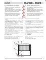
5.1 SCELTA DEL LUOGO DI INSTALLAZIONE
Nella scelta del luogo di installazione si dovrà tenere
conto di:
- Peso dell’unità:
La soletta di appoggio dell’unità deve es se re
perfettamente orizzontale ed in grado di sop-
por ta re il peso in funzionamento del l’uni tà.
È opportuno costruire una soletta di supporto di di men -
sio ni proporzionate all’unità. Ciò si rende in particolar
modo necessario quando l’unità deve es se re posta su
terreno instabile (giardini, terreni di riporto, ecc.).
La soletta deve:
• appoggiare su opportune fondamenta, avere un’al-
tez za, rispetto al terreno circostante, di circa 10-15
cm;
• essere orizzontale ed in grado di sopportare circa
il 200% del peso di esercizio della macchina.
- Spazi:
È necessario verifi care che gli spazi di rispet-
to riportati sul foglio dimensionale del l’uni tà
siano lasciati liberi.
Ridurre lo spazio richiesto può signi care di coltà o
impossibilità di e ettuare le operazioni di ma nu ten zio ne
e/o malfunzionamento dell’unità a causa di ri du zio ne
della portata d’aria che investe la batteria con den san te
o di ricircolo della stessa.
Si fa presente che non sono ammessi osta-
co li quali tettucci, pensiline o coperture in
genere al di sopra della macchina.
Si tenga presente che le unità a pompa di calore
danno luogo a formazione di ghiaccio e condensa.
Si dovrà per tan to prov ve de re a drenare l’acqua di
condensa e sbrinamento, raccolta dalla vaschetta
raccogli condensa, per evitare che il pavimento diventi
sdruc cio le vo le.
Tutta la zona di rispetto dovrà essere in-
ter det ta, fatta eccezione per gli operatori e
manutentori addetti alla macchina.
- Rumore:
Durante il suo funzionamento, l’unità genera del ru mo re;
evitare pertanto l’installazione in ambienti ri ver be ran ti.
L’unità dovrà essere posizionata con il lato batteria rivolto
nella direzione in cui la rumorosità è meno critica.
- Venti predominanti:
Il vento può alterare le condizioni di funzionamento; per
minimizzarne gli e etti si consiglia di posizionare l’unità con il
lato lungo parallelo alla direzione dei venti pre do mi nan ti.
- Vibrazioni:
I supporti antivibranti forniti di serie, permettono di eli-
minare eventuali vibrazioni prodotte dalla macchina.
5 INSTALLATION
5.1 CHOOSING THE INSTALLATION SITE
When choosing the installation site the following points
should be considered:
- The weight of the unit:
The supporting surface under the unit must
be perfectly horizontal and able to withstand
its operating weight.
A supporting surface with an appropriate area should
be built. This is particularly important if the unit is in-
stalled on unstable ground (gardens, embankments,
etc.).
The supporting surface must:
• lie on suitable foundations and be about 10-15 cm
higher than the surrounding ground;
• be horizontal and able to withstand about 200% of
the weight of the unit in operation.
- Spaces:
Make sure that suffi cient free space, as in-
di cat ed on the scale drawing, is left around
the unit.
Less space will make it di cult or impossible to carry
out maintenance operations and/or lead to faults in
the unit due to the reduction in the air ow on the
condenser coil or its recirculation.
Please note that obstacles such as can-
o pies, shelters or coverings in general are
not permitted.
Please note that the heat pump units cause ice and
condensation. This water, collected by the drain pan,
must therefore be drained to prevent the oor from
becoming slippery.
People may not enter the unit area unless
they are authorised operators and main te -
nance personnel.
- Noise:
The unit generates noise while it’s working; do not
install it in reverberating rooms. The unit must be po-
sitioned with the coil side facing the direction where
noise is less critical.
- Prevailing winds:
Wind may alter operating conditions; to minimise its
e ects the unit should be positioned with the long side
parallel to the direction of prevailing winds.
- Vibrations:
The shock absorbers, standard, allow to avoid pos-
sible vibrations of the unit.

16
CHA/CLK - CHA/K
CHA/CLK - CHA/K
5.2 COLLEGAMENTO IDRAULICO
5.2.1 Generalità
Per la realizzazione del circuito idraulico dell’acqua re fri -
ge ra ta è buona norma seguire attentamente le indicazioni
sotto riportate oltre che la normativa vigente.
Attenzione!
Le tubazioni idrauliche devono essere op-
por tu na men te staffate per non gravare con
il loro peso sul refrigeratore.
- Raccordare le tubazioni al refrigeratore tramite giunti
essibili al ne di evitare la trasmissione delle vi bra zio ni
e compensare le dilatazioni termiche.
- Installare sulle tubazioni i seguenti componenti:
• valvole di intercettazione (saracinesche) per isolare
l’unità dal circuito idraulico;
• indicatori di temperatura e pressione per la normale
manutenzione e controllo del gruppo;
• pozzetti sulle tubazioni d’ingresso ed uscita per i
rilievi di temperatura, qualora non fossero presenti
indicatori di temperatura;
• filtro metallico (tubazione in ingresso) a rete con
maglia non superiore ad 1mm, per proteggere lo
scambiatore da scorie o impurità presenti nelle
tu ba zio ni;
• valvola di taratura per la regolazione della portata
acqua
• valvole di s ato, da collocare nelle parti più elevate del
circuito idraulico, per permettere lo sfogo del l’aria;
• eventuale vaso di espansione supple-
mentare, dimensionato in fun zio ne della
quantità d’acqua contenuta nell’impianto
e delle escursioni termiche prevedibili.
• valvole di carico automatico per il manteni-
mento della pressione del sistema e per com-
pensare le dilatazioni ter mi che del uido.
5.2 WATER CONNECTIONS
5.2.1 General
Please carefully carry out the following instructions and
observe current law when installing the chilled water
circuit.
Attention!
The water pipes must be suitably supported
with brackets in order not to weigh on the
chiller.
- Connect the pipes to the chiller with exible joints in
order to prevent the transmission of vibrations and to
compensate thermal expansion.
- Install the following components on the pipes:
• shut-o valve (moisters) for shutting o the water
mains;
• temperature and pressure gauges for routine main-
te nance and inspection purposes;
• check points on the inlet and outlet pipes for meas-
ur ing temperatures if temperature indicators are not
tted;
• metal lter (inlet pipe) with a maximum mesh ap er ture
of 1 mm to protect the exchanger from waste or
impurities in the pipes;
• water ow control valve
• relief valves, tted in the uppermost parts of the
water circuit, for expelling air;
• eventual supplementary expansion tank of a suit-
able size for the quantity of water contained in the
system and the expected temperature range.
• an automatic inlet valve for maintaining the pres-
sure of the system and com pen sat ing the thermal
expansion of the uid.

17
CHA/CLK - CHA/K
CHA/CLK - CHA/K
5.2.2 Evaporatore
È di importanza fondamentale che l’in gres so
dell’acqua avvenga in corrispondenza della
connessione contrassegnata con la targhetta
“ENTRATA ACQUA”.
Per gli attacchi idraulici vengono utilizzate connessioni
lettate maschio (fare riferimento ai disegni dimensionali,
così come per la posizione degli attacchi).
È di fondamentale importanza realizzare il
circuito idraulico in modo tale che venga
garantita la costanza della portata d’acqua
allo scambiatore in qualsiasi condizione di
funzionamento.
Una valvola di sicurezza sul circuito idraulico
fornita di serie, permetterà, in caso di ano-
malie gravi nell’impianto (ad es. in cen dio),
di scaricare il sistema evitando possibili
scoppi. Collegare sem pre lo scarico ad una
tubazione di diametro non inferiore a quello
dell’apertura della val vo la e convogliarlo in
zone nelle quali il getto non possa recare
danno alle persone.
Attenzione!
Durante le operazioni di allacciamento idrau-
li co non operare mai con fi amme libere in
prossimità o all’interno dell’unità.
5.2.2 Evaporator
It is vitally important that the water enters
the unit from the connection point marked
with the “WATER INLET” plate.
Threaded male unions (please refer to the scale draw-
ings which also show the position of the unions).
It is vitally important to connect the water
circuit so that the fl ow of water to the ex-
chang er is always constant under all op er -
at ing conditions.
A safety valve, serially supplied, on the water
circuit. In case of serious system faults (e.g.
fi re) this will allow the system to be drained
in order to prevent the risk of ex plo sions.
Always connect the drain to a pipe with a
diameter not less than that of the valve open-
ing and install the outlet in an area where the
jet cannot cause harm to people.
Attention!
While connecting the water circuit, never
work with naked fl ames near to or inside
the unit.

18
CHA/CLK - CHA/K
CHA/CLK - CHA/K
VSI
MP
PD
ST
VE
MN
VE
VSI
MP
EW
ST1
ST2
PD
EW
ST1
ST2
MN
VSI
ST
MN
VE
CAR
SC
EW
ST1
ST2
PD
EW
ST1
ST2
ANT
ANT
RI
RI
CV FTR
ANT
ANT
RI
RI
CV FTR
ANT
ANT
SFA
RI
RI
CV FTR
PD
MP
ANT
ANT
RI
RI
CV FTR
SFA
SFA
SFA
SFA
SFA
SFA
SFA
MP
RI
RI
VE
VSI SFA
MN
ST
RIC
RI
5.3 COLLEGAMENTI ELETTRICI
5.3.1 Generalità
Queste operazioni devono essere effettuate
solo da personale specializzato.
Prima di effettuare qualsiasi operazione su
parti elettriche assicurarsi che non vi sia
tensione.
Veri care che l’energia disponibile corrisponda ai dati no-
minali dell’unità riportati sulla targhetta (tensione, nu me ro
di fasi, frequenza).
5.3 ELECTRICAL CONNECTIONS
5.3.1 General
These operations may only be carried out
by specialised staff.
Before carrying out any operations on elec-
tri cal components, make sure the unit is dis-
connected from the mains power supply.
Make sure that the mains power supply corresponds to
the rated values of the unit shown on the plate (voltage,
number of phases, frequency).
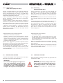
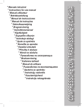
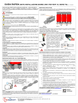
Schema di collegamento impianto idraulico
Hydraulic circuit connection diagram
CHA/CLK
CHA/K
CHA/K/ST
DENOMINAZIONE
ANT Giunti antivibranti
CV Valvola di ritegno
CAR Carico
EW Evaporatore
FTR Filtro a rete
MN Manometro acqua
MP Pompa di circolazione
PD Pressostato di erenziale acqua
RI Valvola di intercettazione a sfera
RIC Valvola carico acqua automatico
SC Scarico acqua
SFA S ato aria automatico
EW Evaporatore
ST Serbatoio inerziale
ST1 Sonda di lavoro
ST2 Sonda antigelo
VE Vaso d'espansione
VSI Valvola di sicurezza
DESIGNATION
Vibration-proof joints ANT
Gate valve CV
Load CAR
Evaporator EW
Messh filter FTR
Water manometer MN
Circulating pump MP
Differential water pressure switch PD
Ball shut-off valve RI
Automatic water filling valve RIC
Water drain SC
Automatic air purge SFA
Evaporator EW
Inertial tank ST
Sensor for unit operation ST1
Antifreeze sensor ST2
Expansion vessel VE
Safety valve VSI
CHA/K/SP

19
CHA/CLK - CHA/K
CHA/CLK - CHA/K
I collegamenti elettrici devono essere e ettuati se guen do
attentamente le istruzioni riportate sul quaderno tecnico
allegato all’unità.
Il collegamento a terra è obbligatorio per legge. Si deve
perciò provvedere al collegamento del cavo di terra con
la barra di terra situata nel quadro elettrico e con tras -
se gna ta con PE.
L’alimentazione del circuito ausiliario è derivata dalla
linea di potenza tramite un trasformatore situato nel
quadro elettrico.
La sezione del cavo e le protezioni di linea
devono essere conformi a quanto indicato
nello schema elettrico e nell’apposita sche da
allegata all’unità.
Rispettare la sequenza delle fasi, viceversa la macchina
non potrà funzionare.
La tensione di alimentazione non deve subire variazioni
superiori a ±5% e lo squilibrio tra le fasi deve essere
sempre inferiore al 2%.
Il funzionamento deve avvenire entro i va lo ri
sopra citati, pena la decadenza im me dia ta
della garanzia.
Una eventuale pompa supplementare deve
essere avviata prima della partenza del
refrigeratore e fermata dopo l’arresto di
quest’ultimo (ritardo minimo con si glia to:
40 secondi).
5.3.2 Consensi esterni
Qualora si desideri e ettuare un ON-OFF remoto del-
l’uni tà è necessario collegare il consenso esterno ai
contatti indicati sullo schema elettrico.
Per il collegamento elettrico al contatto ON-OFF remoto
e funzionamento CHILLER-POMPA DI CALORE remoto,
non installare i cavi di comando all’interno delle canaline
usate per i cavi di potenza; nel caso non fosse possibile,
utilizzare un cavo schermato.
Quando si effettuano i collegamenti de scrit to
nel paragrafo 5.3.2 attenersi scru po lo s-
a men te a quanto riportato nello schema
elettrico e nei kit di istruzione. I cavi di col-
legamento devono ave re sezione minima di
1,5 mm².
Electrical connections must be made carefully follow-
ing the instructions shown on the catalogue attached
to the unit.
The earth connection is obligatory by law. The earth
cable must be connected to the earth bar located in
the electrical panel and marked with PE.
Auxiliary circuit power is supplied by the power line by
means of a transformer located in the electrical panel.
The cross-section of the cable and the line
protections must comply with the in di ca tions
shown on the wiring diagram and in the rela-
tive sheet attached to the unit.
Observe the phase sequence, otherwise the unit will
not work.
Input voltage must not exceed variations of over ±5%
and phase unbalance must always be less than 2%.
Unit operation must always take place within
the above values as otherwise the guarantee
will immediately become null and void.
A possible additional pump must be started
up before starting up the chiller while it must
be stopped after the chiller has stopped (mini-
mum rec om mend ed delay: 40 seconds).
5.3.2 External signals
If a remote ON-OFF command is required, connect the
external enable to the contacts shown on the wiring
diagram.
For the electrical connection to the remote On-o con tact
and remote Chiller heat pump operation, do not install
drive cables inside the ducts used for power cables; if
it is not possible, a shielded cable must be used.
When making the connections described
in paragraph 5.3.2, carefully fol low the in-
dications shown in the wiring di a gram and
instructions kit. The connecting cables must
have a min i mum cross-section of 1,5 mm².

20
CHA/CLK - CHA/K
CHA/CLK - CHA/K
6 AVVIAMENTO
6.1 CONTROLLI PRELIMINARI
AL L’AV VIA MEN TO
- Veri care che i collegamenti elettrici siano stati ese gui ti
correttamente e che siano stati serrati tutti i morsetti.
- Veri care che la tensione sui morsetti L1, L2, L3, sia quella
riportata sulla targa dell’unità (tolleranza am mes sa)
±5% controllabile con un tester. Se av ven go no frequenti
variazioni di tensione, si prega di con tat ta re l'u cio
tecnico di sede per la scelta di opportune pro te zio ni.
- Controllare, eventualmente tramite l’ausilio di un cer ca -
fu ghe, che non vi siano perdite di uido refrigerante.
- Veri care che le resistenze del carter (se presenti) siano
correttamente alimentate.
L’inserimento delle resistenze deve essere
fatto almeno 12 ore prima dell’avviamento,
ed avviene automaticamente alla chiusura
del sezionatore generale (posizione I).
Per controllare se le resistenze funzionano cor ret ta -
men te, veri care che la parte inferiore del com pres so re
sia ad una temperatura di 10÷15°C superiore a quella
ambiente.
- Veri care il corretto collegamento del circuito idrau li co
(de vo no essere rispettate le indicazioni sulle targhette
a bordo macchina).
- Assicurarsi che il circuito idraulico sia stato pre ven ti -
vamen te pulito: si consiglia di e ettuare un lavaggio
del circuito idraulico bypassando l’unità e quindi di
ve ri ca re lo stato di pulizia del ltro dell’impianto.
- Le macchine vengono spedite con s ati e drenaggi
aperti. Apposite targhette indicano le loro posizioni.
Essi vanno chiusi all’atto dell’installazione quando si
riempie il circuito idraulico.
- Verificare che l’impianto idraulico sia stato sfiatato,
eli mi nan do ogni eventuale residuo d’aria; l’operazio-
ne va ese gui ta caricando gradualmente e aprendo i
di spo si ti vi di s ato disposti dall’installatore nella parte
su pe rio re del l’im pian to (a tale proposito consultare la
se zio ne 5.2).
6 START UP
6.1 PRELIMINARY CONTROLS
- Make sure that the electrical connections have been
made correctly and that all the terminals have been
well tightened.
- Use a tester to make sure that the voltage on terminals
L1, L2, L3, is equal to that shown on the rating plate
(permitted tolerance ±5%). If voltage is subject to fre-
quent variations, please contact technical main o ce
in order to decide on suitable protection devices.
- Use a leak tester, if necessary to make sure there are
no leaks of refrigerant liquid.
- Check that the heating elements of the sump (if tted)
are correctly powered.
The heating elements must be turned on
at least 12 hours before start up; this takes
place automatically when the main power
switch is closed (position I).
To check if the heating elements work correctly, make
sure that the lower part of the compressor is 10÷15°C
higher than room temperature.
- Check the water circuit is correctly connected (the indi-
cations on the unit rating plate must be observed).
- Make sure that the water circuit has been cleaned
beforehand: the water circuit should be washed, by-
pass ing the unit, and then the system lter checked
for dirt.
- The units are despatched with the relief valves and
drains open. Special plates show where they are lo-
cat ed. They must be closed during installation before
the water circuit is lled.
- Make sure the water circuit has been well vented to
eliminate any air residues; this operation is carried
out by gradually loading and opening the relief valves
tted to the uppermost part of the unit by the installer
(please consult section 5.2 for further information).
Page is loading ...
Page is loading ...
Page is loading ...
Page is loading ...
Page is loading ...
Page is loading ...
Page is loading ...
Page is loading ...
Page is loading ...
Page is loading ...
Page is loading ...
Page is loading ...
-
 1
1
-
 2
2
-
 3
3
-
 4
4
-
 5
5
-
 6
6
-
 7
7
-
 8
8
-
 9
9
-
 10
10
-
 11
11
-
 12
12
-
 13
13
-
 14
14
-
 15
15
-
 16
16
-
 17
17
-
 18
18
-
 19
19
-
 20
20
-
 21
21
-
 22
22
-
 23
23
-
 24
24
-
 25
25
-
 26
26
-
 27
27
-
 28
28
-
 29
29
-
 30
30
-
 31
31
-
 32
32


Clint CHA CLK 15÷81 CHA K 91÷151 User manual
- Category
- Heat pumps
- Type
- User manual
Ask a question and I''ll find the answer in the document
Finding information in a document is now easier with AI
in other languages
Related papers
-
Clint RTA User manual
-
-
-
-
-
-
-
Other documents
-
 Strongline XT200900N User manual
-
 Mecafer Power Monster 200L User manual
-
MAXA VE Owner's manual
-
GGM Gastro BSW1400 Exploded View
-
 Gastrodomus ICE450Q Owner's manual
-
 Gastrodomus ICE320Q Owner's manual
-
-
Modine PKE Technical Manual
-
 TECSYSTEM UNIVERSAL BAR DIAM 80 Quick start guide
-
Tecnosystemi COMPACT 30 compact ceiling-mounted ductable static heat recovery units Owner's manual


