Page is loading ...

PUB IB04300001E
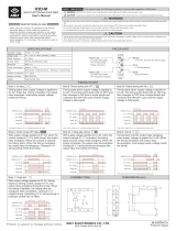
D64RPB125 DIGITAL GROUND FAULT RELAY
Revision 1
September, 2004 Page 1
D64RPB125 INSTRUCTION MANUAL
CANADA
U.S.A
Eaton Yale Ltd. Eaton Electrical Inc.
3228 South Service Road Power & Control Systems Operations
Burlington, Ontario 2900 Doc Bennett Road
L7R 3Y8 Fayetteville, NC
28306
R39
J1
ON
OFF
1
23
4
5
6
78
SW1
J2
D1
D10
S1
C14
C6
C16
L+ N- R2 R1 14 13 12 11
24-125V
AC/DC
TEST/
RESET
N.O. N.C.
INTERNAL CT SENSOR
:
In (A) = 125
I n (A) = 0.1-2
RATINGS
RUN
TRIP
RESET
DOUBLE CLICK
FOR TEST
T
RJ-12
F2022-00-00
D64RPB125
DIGITAL GROUND FAULT RELAY

PUB IB04300001E
D64RPB125 DIGITAL GROUND FAULT RELAY
Revision 1
September, 2004 Page 2
TABLE OF CONTENTS
PAGE
TABLE OF CONTENTS
.................................................................................................................................................. 2
LIST OF TABLES, FIGURES & FORMS
.......................................................................................................................... 2
1.
GENERAL DESCRIPTION
.................................................................................................................................. 3
2.
OPERATION
.................................................................................................................................................. 3
2.1 GLOSSARY OF TERMS ........................................................................................................................ 3
2.2
DIP
SWITCH SETTINGS ........................................................................................................................ 5
2.2.1 OUTPUT RELAY OPERATING MODE..................................................................................... 6
2.2.2 GROUND FAULT TRIP DELAY TIME ..................................................................................... 6
2.2.3 GROUND FAULT TRIP CURRENT LEVEL.............................................................................. 6
2.3 OUTPUT RELAY CONTACT STATE ..................................................................................................... 7
2.4 INDICATION........................................................................................................................................... 7
2.5 RESET .................................................................................................................................................. 7
2.6 GROUND FAULT TEST ......................................................................................................................... 7
3.
INSTALLATION INSTRUCTIONS
....................................................................................................................... 8
3.1 MOUNTING ............................................................................................................................................ 8
3.2 BUILT-IN CURRENT TRANSFORMERS ............................................................................................... 8
3.3 CONNECTIONS ..................................................................................................................................... 8
3.3.1 CONNECTING MORE THAN ONE D64RPB125 TO REMOTE TEST/RESET ........................ 9
4.
COMMUNICATIONS AND OPTIONAL EXTERNAL VERIFY/INDICATOR UNITS
............................................ 9
4.1 D64DMCC REMOTE TRIP & VERIFY UNIT .......................................................................................... 9
5.
CATALOG NUMBERS
........................................................................................................................................ 10
6.
TECHNICAL SPECIFICATIONS
......................................................................................................................... 10
LIST OF TABLES, FIGURES & FORMS
TABLE NO.
PAGE
1. DIPSWITCH SETTINGS...................................................................................................................................... 6
2. OUTPUT RELAY CONTACT STATES ................................................................................................................ 13
FIGURE NO.
1. TYPICAL FIELD CONNECTION .......................................................................................................................... 14
2. DIMENSIONS AND WEIGHTS OF D64RPB125 RELAY .................................................................................... 15
3. DIMENSIONS AND WEIGHTS OF D64DMCC REMOTE TRIP & VERIFY UNIT ............................................... 16
FORM NO.
1. TEST RECORD .................................................................................................................................................. 17

PUB IB04300001E
D64RPB125 DIGITAL GROUND FAULT RELAY
Revision 1
September, 2004 Page 3
1. GENERAL DESCRIPTION
The D64RPB125 is a microprocessor based ground fault relay for use on solidly grounded or resistance grounded systems. This
innovative digital electronic relay measures ground fault current using 3 built-in current transformers and an electronic zero
sequence circuit.
The D64RPB125 reacts to alternating current only and will reject direct current signals. It will maintain accuracy over a frequency
range of 45 to 65Hz, filtering out harmonics which could cause nuisance tripping, making it ideal for use on systems employing
static switching.
660 Volts is the maximum system operating voltage for the D64RPB125 when passing the system power conductors through the
built-in CTs. The CTs are positioned within the relays so that they line up with the terminals on the associated Eaton’s Cutler-
Hammer E125 (15 – 125 A) Frame circuit breaker.
The ground fault current trip level is set on a front accessible binary DIPswitch array. Trip currents can be selected in 8 discrete
steps from 0.1 Amp – 2.0 Amps. The trip level can be set just above the charging current
1
. Any deterioration in the circuit will trip
the relay. This also permits scheduled field testing of the relay (by lowering the trip level).
1
The capacitance-to-ground charging current on a system will vary depending on: the overall length of the cables; the
types of loads; the quality of insulation on the phase conductors; the surrounding equipment grounding, cable trays,
junction boxes, etc.; and, the type of transformer.
A "Rule-of-Thumb" for systems 600 Volts and lower: The charging current is 0.5 Amps per 1000 kVA of transformer
capacity.
The response time on ground fault trip is set on a front accessible binary DIPswitch array. Trip times from 20 milliseconds to 5.0
seconds can be selected in 8 discrete steps.
The output relay has Form “Z” (4 terminal) N.O. and N.C. contacts which may be used to operate the upstream protective device
and to indicate a failure of the system. The relay can be set to operate in any one of the following modes: Failsafe; Non-failsafe;
Auto Reset, or Pulsed operation by means of 2 front accessible DIPswitches.
By double clicking the cover mounted Reset button, the Reset button on the D64DMCC connected to the RJ –12 port, or a
remote Test/Reset button connected to terminals R1 and R2, a functional test of the D64RPB125 is invoked. A single press of
any of the above Reset buttons resets the relay after a trip. (It is not necessary to press the Reset buttons when the Auto Reset
or Pulsed operating modes are selected). A green RUN LED flashes to indicate when control power is applied to terminals N-
and L+. A red TRIP LED flashes to indicate the relay has sensed a ground fault current higher than the trip level for a period
longer than the trip time and that the output contacts have operated.
The 8 point terminal block is pull-apart simplifying connection of field wiring.
The D64RPB125 operates on any control voltage from 24 to 125 Volts ac or dc.
2. OPERATION
2.1 GLOSSARY OF TERMS
Manual Reset:
The cover mounted Reset pushbutton, the Reset button on the D64DMCC connected to the RJ –12 port, or a
N.O. contact remote Test/Reset pushbutton connected to terminals R1 and R2 of the D64RPB125 must be
pressed once to reset the output relay after a trip, providing the ground fault has been cleared or the measured
values are within the preset limits.
Auto Reset:
The output relay N.O. contact is closed when tripped and the N.C. contact is open when tripped.
The output relay does not change state when control power is applied to terminals N- & L+.
With control voltage on terminals N- & L+ (green RUN LED flashing), when the measured values reach or
exceed the DIPswitch settings for current and time, the output relay changes state (trips) and the red TRIP LED
flashes. The output relay will remain tripped until one of the following conditions is met:

PUB IB04300001E
D64RPB125 DIGITAL GROUND FAULT RELAY
Revision 1
September, 2004 Page 4
-
Three seconds after the ground fault current drops below the trip current set point the relay will reset
and the red TRIP LED is turned off.
-
If the control voltage is removed by the trip action of the output relay (i.e. it operates the shunt trip of
the breaker that is providing the control voltage), the relay will reset with a short delay and the red
TRIP LED is turned off.
If the ground fault has not been cleared when control voltage is restored, the relay will trip and the red TRIP
LED will light after 500 milliseconds, regardless of the time delay set on the Trip Delay DIPswitch, and the
above cycle will be repeated.
If the ground fault has been cleared when control voltage is restored, the relay will remain reset.
The Auto Reset mode can be used when the application calls for Auto Reset.
Pulsed Operation (manual Reset of red TRIP LED register):
The output relay N.O. contact is closed during a trip pulse and the N.C. contact is open during a trip pulse.
The output relay does not change state when control power is applied to terminals N- & L+.
With control voltage on terminals N- & L+ (green RUN LED flashing), when the measured values reach or
exceed the DIPswitch settings for current and time, the output relay begins 0.5 second pulse trips every 3
seconds and the red TRIP LED flashes. The output relay will continue these 0.5 second pulses until one of the
following conditions is met:
-
As soon as the ground fault current drops below the trip current set point the relay will remain in the
reset mode. However the red TRIP LED will continue to flash, registering the trip and the green RUN
LED will remain off. Pressing the Reset button will cancel the register, the red TRIP LED will turn off
and the Green RUN LED will flash.
-
If the control voltage is removed by the trip action of the output relay (i.e. it operates the shunt trip of
the breaker that is providing the control voltage), the relay stops pulsing and remains in the reset mode
and the red TRIP LED is turned off.
If the ground fault has not been cleared when control voltage is restored, after 500 milliseconds the relay will
resume the 0.5 second pulsed trips and the red TRIP LED will flash, regardless of the time delay set on the
Trip Delay DIPswitch, and the above cycle will be repeated.
If the ground fault has been cleared when control voltage is restored, the relay will remain reset and the green
RUN LED will flash.
The Pulsed operating mode is designed for applications where the output relay is operating a shunt trip device.
Since the D64RPB125 output relay limits the trip pulse to 0.5 seconds every 3 seconds, this avoids energizing
the shunt trip coil for extended periods. Also, this prevents damage to the internal mechanism of the circuit
breaker in the event that the operator tries to reset the circuit breaker.
Non-Failsafe:
The output relay N.O. contact is closed when tripped and the N.C. contact is open when tripped.
The output relay does not change state when control power is applied to terminals N- & L+.
With control voltage on terminals N- & L+ (Green RUN LED flashing), when the measured values reach or
exceed the DIPswitch settings for current and time, the output relay changes state (trips) and the red TRIP LED
flashes.
If control voltage is maintained on terminals N- & L+ after a ground fault trip, the cover mounted RESET button,
the Reset button on the D64DMCC connected to the RJ –12 port, or the remote Test/Reset button must be
pressed to reset the relay after clearing the ground fault.

PUB IB04300001E
D64RPB125 DIGITAL GROUND FAULT RELAY
Revision 1
September, 2004 Page 5
If control voltage is removed from terminals N- & L+ while a ground fault is detected, the output relay resets
and the red TRIP LED turns off.
If the ground fault has not been cleared when control voltage is restored, after 500 milliseconds the relay will
trip and the red TRIP LED will resume flashing, regardless of the time delay set on the Trip Delay DIPswitch.
If the ground fault has been cleared when control voltage is restored, the relay will remain reset.
The Non-Failsafe mode can be used when the output relay is operating undervoltage devices. This includes:
contactor coils; starter coils, and circuit breakers equipped with UV trip coils.
Failsafe:
The output relay N.O. contact is closed when tripped and the N.C. contact is open when tripped.
The output relay contacts change state 500 milliseconds after control voltage is applied to terminals N- & L+.
The output relay trips when either or both of the following conditions occur:
- The measured values reach or exceed the DIPswitch settings for current and time. In this condition the
red TRIP LED flashes.
- Control voltage is removed from terminals N- & L+. In this condition the green RUN LED turns off.
If control voltage is maintained on terminals N- & L+ after a ground fault trip, the cover mounted RESET button,
the Reset button on the D64DMCC connected to the RJ –12 port, or the remote Test/Reset button must be
pressed to reset the relay after clearing the ground fault.
If control voltage is removed from terminals N- & L+ after a ground fault is detected, the output relay remains
tripped.
If the ground fault has not been cleared when control voltage is restored, the relay remains in the tripped
condition, regardless of the time delay set on the Trip Delay DIPswitch. The red TRIP LED flashes.
If the ground fault has been cleared when control voltage is restored, the relay contacts will change state 1
second after control voltage is applied to terminals N- & L+ and the green RUN LED flashes.
The Failsafe mode can be used when the output relay is operating undervoltage devices. This includes:
contactor coils; starter coils; and circuit breakers equipped with UV trip coils provided that the control voltage to
the D64RPB125 is not interrupted by the action of the UV trip.
Chassis Ground
Chassis ground is the ground to which all of the non-current carrying metal equipment is connected/bonded.
Typically, equipment grounding is provided by means of a ground bus. A solid connection is to be made from
terminal N- of the D64RPB125 to the nearest chassis ground to ensure the relay complies with the specified
Electromagnetic compatibility (EMC) standards.
2.2 DIPSWITCH SETTINGS
FOR MAXIMUM SAFETY THE SETTINGS DESCRIBED IN THIS SECTION SHOULD BE MADE WITH CONTROL
VOLTAGE REMOVED FROM THE D64RPB125 RELAY.
The DIPswitches are mounted inside of the relay and are accessible through the front cover. It is recommended that all
of the DIPswitches be set at one time.
Should it be necessary to make changes to the DIPswitch settings when the D64RPB125 relay is energized, this can be
done without having any adverse effect on the performance of the relay.
Please Refer to Table 1. This provides a list of the 8 DIPswitches, the function of each group, and the values related to
each setting. The DIPswitches are numbered from 1 to 8 left to right.

PUB IB04300001E
D64RPB125 DIGITAL GROUND FAULT RELAY
Revision 1
September, 2004 Page 6
TABLE 1 – DIPSWITCH SETTINGS
In the table below ‘D’ denotes down and ‘U’ denotes up.
Dipswitch settings (* = factory setting)
Switch Function Set to Meaning on D64RPB125
1 2 Trip relay operation mode D D *
D U
U D
U U
Non-failsafe operation with manual reset
Failsafe operation with manual reset
Auto reset operation (reset delay 3 seconds after G/F removed)
Pulsed operation – 0.5 second pulse (with manual reset of red TRIP
LED register)
3 4 5 Trip time delay D D D *
D D U
D U D
D U U
U D D
U D U
U U D
U U U
20 ms
50 ms
100 ms
200 ms
500 ms
1 s
2 s
5 s
6 7 8 Trip current limit D U U
D U D
D D U
D D D *
U U U
U U D
U D U
U D D
0.1 A
0.2 A
0.3 A
0.4 A
0.5 A
1.0 A
1.5 A
2.0 A
2.2.1 OUTPUT RELAY OPERATING MODE - DIPSWITCHES 1 & 2
Referring to the Glossary of Terms, determine if FAILSAFE, NON-FAILSAFE, AUTO RESET, or PULSED operation of
the output relay is required. The factory setting is NON-FAILSAFE with DIPswitches 1 & 2 in the
D
own position.
Refer to Table 1 for DIPswitch settings for FAILSAFE, AUTO RESET, and PULSED operation.
2.2.2 GROUND FAULT TRIP DELAY TIME – DIPSWITCHES 3, 4, & 5
The ground fault TRIP DELAY time range is 20 milliseconds - 5.0 seconds. Table 1 provides a listing of the eight TRIP
DELAY settings, which can be made with DIPswitches 3, 4, & 5.
The TRIP DELAY time begins when the ground fault trip level setting is reached or is exceeded.
Set the ground fault TRIP DELAY time to provide the desired delay before the output relay changes state when the
ground fault TRIP LEVEL setting is reached or exceeded.
The setting should be selected to co-ordinate with other ground-fault devices connected on the same transformer
secondary: set shorter than upstream devices; set longer than downstream devices. If no other ground-fault devices are
connected, set for the shortest time.
2.2.3 GROUND FAULT TRIP CURRENT LEVEL - DIPSWITCHES 6, 7, & 8
The ground fault TRIP LEVEL range is 0.1 Amps – 2.0 Amps. Table 1 provides a listing of the eight TRIP LEVEL
settings, which can be made on DIPswitches 6, 7, & 8.

PUB IB04300001E
D64RPB125 DIGITAL GROUND FAULT RELAY
Revision 1
September, 2004 Page 7
As indicated in the General Description, it is recommended that the ground fault TRIP LEVEL setting be kept as close to
the charging current as possible. This will provide maximum safety for operating personnel and equipment protection.
On resistance grounded systems, the TRIP LEVEL setting should be set lower than 20% of the Neutral Grounding
Resistor let-through current.
If the measured ground fault current exceeds the TRIP LEVEL setting, the output relay changes state after the pre-
selected TRIP DELAY time.
2.3 OUTPUT RELAY CONTACT STATE
The output relay contact state is determined by the operating mode selected and the sensing condition of the
D64RPB125 relay. This is shown in Table 2. Use this table when deciding on field connections. Refer to the
CONNECTIONS section.
2.4 INDICATION
There are two LED’s on the front of the
D64RPB125
.
GREEN RUN LED
RED TRIP LED CONDITION INDICATED
FLASHING OFF
D64RPB125
OKAY
OFF FLASHING GROUND FAULT TRIP
OFF OFF NO CONTROL VOLTAGE OR
D64RPB125
DEFECTIVE
ANY OTHER COMBINATION CONTROL VOLTAGE TOO LOW OR
D64RPB125
DEFECTIVE
2.5 RESET
The
D64RPB125
has a built in momentary RESET button, an RJ-12 port for connection of the D64DMCC, and two
terminals, R1 and R2, for a remote N.O. Test/Reset button. After a trip, the electronics remain in the tripped state until
the ground fault has been cleared and the Reset button has been pressed, or the control voltage is removed from
terminals L- & N+.
It is
NOT
necessary to press any of the reset buttons after the ground fault has been cleared when the
D64RPB125
is
set in the Auto Reset. In this mode the relay will reset automatically. In the Pulsed mode the relay resets automatically.
However, one of the Reset buttons should be pressed to cancel the flashing red TRIP LED register and restore the
flashing green RUN LED.
2.6 GROUND FAULT TEST
Double clicking any of: the RESET button on the front of the relay; the Reset button on the D64DMCC connected to the
RJ –12 port: or the remote Test/Reset button connected to terminals R1 and R2, invokes a relay test. A simulated
current equal to 1.2 times the trip current set on the Trip Level DIPswitches replaces the measured current. After the trip
delay time set on the Trip Delay DIPswitch has elapsed, the unit should trip and the red TRIP LED will flash. This
procedure tests the functionality of the unit.
After the trip, if the relay operating mode is Non-Failsafe or Failsafe, the output relay will remain tripped and the red
TRIP LED will flash until the button is pressed (Manual Reset)
After the trip, if the relay operating mode is Auto Reset, 3 seconds later the output relay will reset, the red TRIP LED will
turn off, and the green RUN LED will flash.

PUB IB04300001E
D64RPB125 DIGITAL GROUND FAULT RELAY
Revision 1
September, 2004 Page 8
After the trip, if the relay operating mode is Pulsed, 0.5 seconds later the output relay will reset. However the red TRIP
LED will continue to flash, registering the trip and the green RUN LED will remain off. Pressing the Reset button will
cancel the register, the red TRIP LED will turn off and the Green RUN LED will flash.
A “Test Record Form” is included in this instruction manual. This form provides spaces to record the date the test was
performed and the results. Those in charge of the building’s electrical installation should retain the form in order to be
available to the authority having jurisdiction.
3. INSTALLATION INSTRUCTIONS
Place the
D64RPB125
in a clean dry enclosure. Try to keep the exposure to mechanical shock and vibration to a
minimum, even though the internal electronics have been encapsulated in epoxy to improve the performance in high
vibration environments.
Locate the relay close to the isolating device (circuit breaker) that is protecting the circuit being monitored.
Provide maximum clearance between the
D64RPB125
and any strong magnetic flux producing devices such as
power transformers, autotransformers, control transformers, reactors, and high power conductors and buswork.
3.1 MOUNTING
Refer to Figure 2 for mounting dimensions of the
D64RPB125
relay. It is designed for mounting from the front with two
#8 x 1.25" self threading pan head mounting screws. The heads of these screws seat against blind inserts imbedded in
each mounting hole.
3.2 BUILT-IN CURRENT TRANSFORMERS
The
D64RPB125
has 3 built-in current transformers with 0.49” (12.5mm) openings on 1“(25.4mm) centers. The Trip
Level range is 0.1 Amps to 2.0 Amps. The maximum continuous primary phase current is to be 125 Amps.
Phase conductors must be insulated for the system voltage when it is higher than 660 Volts.
Pass the phase conductors through the CT windows. Do not pass ground conductors through the CT windows. In
applications that require shielded wires to pass through the CT window, return the shields through the CT window
before connecting them to ground.
Verify that the polarity of the conductors is correct when they pass through the CT. Verify that ground paths do not exist
that would bypass the CT.
Position power cables in the center of the current transformer opening.
There is no provision for a neutral conductor. If a current carrying neutral conductor is part of the circuit that is to be
monitored select the D64RPB100 ground fault relay.
3.3 CONNECTIONS
All connections to the
D64RPB125
are by means of screw clamp terminals rated 10 Amps, 300 Volts. Terminals will
accept #26-12 AWG solid or stranded conductors.
The terminals are pull apart. A screw mounted locking block is located at each end of the 8 point terminal block for
maximum security.
An RJ-12 port is provided for connection of a D64DMCC display suitable for mounting in the Eaton’s Cutler-Hammer
MCC door mounted panel. See section 4.

PUB IB04300001E
D64RPB125 DIGITAL GROUND FAULT RELAY
Revision 1
September, 2004 Page 9
For remote Test and Reset connect a N.O. momentary contact TEST/RESET button to terminals R1 and R2.
Note
: Terminals R1 and R2 are NOT isolated from the control voltage; terminal R2 is internally connected to terminal
N-.
Connect ac or dc control power to terminals N- and L+. Observe polarity.
In order to meet the Electromagnetic Compatibility (EMC) requirements a chassis bond is required between terminal N-
and the nearest ground point. This distance should be kept to an absolute minimum.
Refer to Figure 1 and Table 2. Decide on the connection of field devices to control voltage and output relay contact
terminals by comparing the desired control of the field devices under various operating conditions.
Figure 1 shows the
D64RPB125
using its built-in current transformers and close coupled to the load side of a circuit
breaker with a shunt trip coil (ST). Pulsed operating mode has been selected. Comparing the operating mode and the
relay contact states in Table 2, it can be seen that the N.O. contact, terminals 13 and 14, would be used for the shunt
trip coil. The
D64RPB125
will give a 0.5 second pulse trip and then reset. The ground fault current is interrupted by
the tripping action of the circuit breaker.
3.3.1 CONNECTING MORE THAN ONE D64RPB125 TO REMOTE TEST/RESET
Up to 5 D64RPB125 relays in the same enclosure may share a common remote Test/Reset button. Connect one
terminal of the button to terminal R2 of
one
of the units, and connect the other terminal of the button to terminals R1 of
all
the units in parallel.
4. COMMUNICATIONS AND OPTIONAL EXTERNAL VERIFY/INDICATOR UNIT
The D64RPB125 has a communication port. This may be used for connection to the D64DMCC Remote Trip and Verify
Unit. This is a modular 6 pole RJ-12 connector carrying 5 Volts dc supply voltage, 3 data signals, and common. The
maximum cable length is 10 feet (3m).
4.1 D64DMCC REMOTE TRIP & VERIFY UNIT
The D64DMCC Remote Trip & Verify Unit is connected to the D64RPB125 by up to 10 feet/3 m of low cost 6-wire
telephone type cable. It provides the following remote indications and functions:
GREEN RUN LED
RED TRIP LED CONDITION INDICATED
FLASHING OFF D64RPB125 OKAY
OFF FLASHING GROUND FAULT TRIP
OFF OFF NO CONTROL VOLTAGE OR
D64RPB125 DEFECTIVE
ANY OTHER COMBINATION CONTROL VOLTAGE TOO LOW OR
D64RPB125 DEFECTIVE
RESET: To reset relay and LED after a trip. Double Click to invoke Test (See 2.6 Ground Fault Test for a description of
the test procedure).
VERIFY: By pushing the VERIFY button on the Remote Display the D64DMCC will show if the D64RPB125 to which it
is connected tripped due to a ground fault prior to loss of its control voltage by lighting the red TRIP LED. If there was
no ground fault trip prior to loss of control voltage the green RUN LED will light. This feature is especially useful when
pulse tripping a breaker that also supplies control voltage to the D64RPB125. This indication will remain available for at
least ten hours. The D64DMCC will reset automatically when control voltage is restored.

PUB IB04300001E
D64RPB125 DIGITAL GROUND FAULT RELAY
Revision 1
September, 2004 Page 10
5. CATALOG NUMBERS
D64RPB125 Ground Fault Relay with 3 built-in 0.49” (12.5mm) CTs, 24 – 125 Volts ac or dc control voltage, for use
on 660 Volts maximum, 50/60 Hz power system. 1” (25.4mm) CT center-to-center spacing aligns with
Eaton’s Cutler-hammer E125 Frame 3 pole circuit breaker.
D64DMCC Remote Trip and Verify Unit with 2 LEDs, Test and Verify buttons, mounts in 2.72” wide x 3.33”high
(69mm x 85mm) cutout in Eaton’s Cutler-Hammer MCC Door.
6. TECHNICAL SPECIFICATION
Control Voltage (non-isolated) ................................................................................................... 24 – 125 Volts ac or dc
Power consumption.......................................................................proportional to voltage: 0.3 VA/W @ 24 V ac/dc
1.5 VA/W @ 125 V ac/dc
Operating voltage tolerance ................................................................... 80% to 110% of rated voltage 24 -33 V ac
55% to 110% of rated voltage 33 – 125 V ac
80% to 110% of rated voltage 24 – 125 V dc
Under voltage tolerance (no impaired operation) ........................................withstands loss of supply up to 500 ms
Power Up Time.............................................................................................................................. 500 milliseconds
Maximum System Voltage & Frequency ................................................................................. 660 Volts ac, 45 to 65 Hz
Output Relay:
Contacts: Maximum UL rating: 5 A @ 250 Vac, general use
5 A @ 30 Vdc, resistive
1/8 hp, 250 Vac
2 A, 250 VA, @ 125 Vac, pilot duty
1 A, 250 VA, @ 250 Vac, pilot duty
0.88 A, 26.4 VA, @ 30 Vdc, pilot duty
EN 60947-5-1 rating: 5 A @ 250 Vac, Utilization category AC-12
4 A @ 250 Vac, Utilization category AC-13
3 A @ 250 Vac, Utilization category AC-14, AC15
5 A @ 30 Vdc, Utilization category DC-12
3 A @ 24 Vdc, Utilization category DC-13
Maximum fusing under EN 60947-5-1: ............................................................ 13 A
Isolation voltage ........................................................................................ 3 kV rms, 50-60 Hz, 1 min.
Between open contacts.............................................................................. 1 kV rms, 50-60 Hz, 1 min.
Between contact sets................................................................................. 2 kV rms, 50-60 Hz, 1 min.
Configuration.....................................................Voltage free form "Z" 1 N.O. and 1 N.C. (4 terminals)
Operating Mode (Selected on DIPswitches 1 & 2)............................................................Non-Failsafe-Manual Reset
Failsafe-Manual Reset
Auto Reset – 3 seconds after ground fault removed
0.5 second Pulsed Trip, Manual Reset of red TRIP LED Register
Ground Fault Circuit:
Ground Fault Trip Current Level:...................................... 8 settings: 0.1, 0.2, 0.3, 0.4, 0.5, 1.0, 1.5, and 2.0 Amps
Setting within the Range....................................................................... DIPswitches 6, 7, & 8, on front of relay

PUB IB04300001E
D64RPB125 DIGITAL GROUND FAULT RELAY
Revision 1
September, 2004 Page 11
Ground Fault Trip Current Level Accuracy
Ground Fault Trip
level setpoint
∅
∅∅
∅
Current = 10
A
∅
∅∅
∅
Current = 20
A
∅
∅∅
∅
Current =
50 A
∅
∅∅
∅
Current =
100 A
∅
∅∅
∅
Current =
125 A
0.1 A
±
15 %
±
15 %
±
25 %
±
40 %
±
50 %
0.2 A
±
15 %
±
15 %
±
15 %
±
25 %
±
30 %
0.3 A
±
15 %
±
15 %
±
15 %
±
15 %
±
20 %
Other settings
±
15 %
±
15 %
±
15 %
±
15 %
±
15 %
Ground Fault Trip Time Delay ................................................................................... 20 milliseconds –5.0 seconds
Setting within Range.............................................................................. DIPswitches 3, 4, & 5 on front of relay
Ground Fault Trip Time Delay Accuracy
Trip delay setpoint @ 1.2 x Ground
Fault setpoint
@ 2 x Ground
Fault setpoint
@ 4 x Ground
Fault setpoint
@
≥
≥≥
≥
6 x Ground
Fault setpoint
20 ms 59 – 91 ms 36 – 54 ms 25 – 41 ms 19 – 35 ms
50 ms 90 – 123 ms 67 – 86 ms 56 – 73 ms 50 – 67 ms
100 ms 140 – 173 ms 117 – 136 ms 106 – 123 ms 100 – 117 ms
200 ms 240 – 273 ms 217 – 236 ms 206 – 223 ms 200 – 217 ms
500 ms 540 – 573 ms 517 – 536 ms 506 – 523 ms 500 – 517 ms
1.0 s 1018 – 1082 ms 995 – 1045 ms 984 – 1032 ms 978 – 1026 ms
2.0 s 2018 – 2082 ms 1995 – 2045 ms 1984 – 2032 ms 1978 – 2026 ms
5.0 s 5018 – 5082 ms 4995 – 5045 ms 4984 – 5032 ms 4978 – 5026 ms
Frequency Response Range.................................................................................................................... 45 - 65 Hz
Functional Test:
A simulated current equal to 120% of the trip current set on the Trip Level DIPswitches replaces the measured
current. This tests all internal electronics and secondary windings of the built-in current transformers. No
external power supply or additional wiring is required.
Local Test................................................................................................... Double click RESET button on front of relay
Remote Test...................................................Double click button connected to terminals R1 and R2 or via D64DMCC
Reset...................................................................................................... Single push of RESET button on front of relay
Remote Reset ........................................... Single push of button connected to terminals R1 and R2 or via D64DMCC
Reset mode.................................................................................................. Manual, Auto Reset, or Pulsed Trip/Reset
Environment:
Operating Temperature ............................................................................................................. -35
°
C to +60
°
C
Storage ...................................................................................................................................... -40
°
C to +80
°
C
Humidity....................................................................................................................... 85% (No Condensation)
Shock resistance............................................................................................................................ 10G (no malfunction)
Vibration resistance.......................................................... 10G, 10-55 Hz at 1.5 mm double amplitude (no malfunction)

PUB IB04300001E
D64RPB125 DIGITAL GROUND FAULT RELAY
Revision 1
September, 2004 Page 12
Ingress protection..................................................................................................................................................... IP20
Dimensions (refer to Figure 2):
Height .......................................................................................................................................... 2.20" (56 mm)
Width ........................................................................................................................................... 3.70" (94 mm)
Depth (not including terminal blocks) .......................................................................................... 2.83" (72 mm)
Depth (including terminal blocks) ................................................................................................ 3.74” (95 mm)
Mounting (refer to Figure 2):
From front ..............................................................................Two self threading pan head screws - #8 x 1.25"
Weight:
Open.......................................................................................................................................1.26 lbs (0.57 kg)
Packaged................................................................................................................................1.81 lbs (0.82 kg)
Applicable Standards:
EN 61000-6-3 Electromagnetic compatibility (EMC) - Part 6-3 Generic standards– Emission standard for
residential, commercial and light-industrial environments (note: = lowest levels):
30-230 MHz 30 dB
µ
V at 10m distance
230-1000 MHz 37 dB
µ
V at 10m distance
EN 61000-6-2 Electromagnetic compatibility (EMC) - Part 6-2 Generic standards– Immunity standard for
industrial environments (note: = highest levels):
80-1000 MHz with 80% AM modulation up to 10 V/m at 3m distance from source
EN 61000-4-2 Electromagnetic compatibility (EMC) for industrial-process measurement and control
equipment – Part 4-2: Electrostatic discharge (ESD) immunity
EN 61000-4-3 Electromagnetic compatibility (EMC) for industrial-process measurement and control
equipment – Part 4-3: Radiated electromagnetic field immunity
EN 61000-4-4 Electromagnetic compatibility (EMC) for industrial-process measurement and control
equipment – Part 4-4: Electrical fast transient/burst immunity
EN 61000-4-5 Electromagnetic compatibility (EMC) for industrial-process measurement and control
equipment – Part 4-5: Surge immunity
EN 61000-4-6 Electromagnetic compatibility (EMC) for industrial-process measurement and control
equipment – Part 4-6: Conducted radio frequency field immunity
EN 61000-4-11 Electromagnetic compatibility (EMC) for industrial-process measurement and control
equipment – Part 4-11: Voltage dips/drops/variations immunity
EN 60947-5-1 Low-voltage switchgear and controlgear – Part 5-1: Control circuit devices and switching
elements – Electromechanical control circuit devices
UL UL 1053 Ground-Fault Sensing and Relaying Equipment, Class 1
UL File E195341
CSA C22.2 No. 144-M91 Ground Fault Circuit Interrupters
CSA File 700103
CE CE mark – Declaration of Conformity

PUB IB04300001E
D64RPB125 DIGITAL GROUND FAULT RELAY
Revision 1
September, 2004 Page 13
TABLE 2 – OUTPUT CONTACT STATES
STATE OF OUTPUT RELAY CONTACTS UNDER VARIOUS OPERATING CONDITIONS
WITH DIPSWITCHES 1 & 2 IN SELECTED POSITIONS
OPERATING
CONDITIONS
NON-FAILSAFE
1-Down, 2-Down
FAILSAFE
1-Down, 2-Up
AUTO RESET
1-Up, 2-Down
PULSED TRIP
1-Up, 2-Up
13 14 11 12 13 14 11 12 13 14 11 12 13 14 11 12
1.CONTROL POWER
OFF
2.CONTROL POWER ON
+ 500ms
=
+ 500ms
=
3.CONTROL POWER
ON, FAULT CURRENT
ABOVE TRIP SETTING
& TRIP TIME
Cycles
for 0.5s
every 3s
Cycles
for 0.5s
every 3s
4.CONTROL
POWER
ON,
FAULT
CLEARED
NO
RESET
REQUES
T
for 3s then
for 3s then
Red RUN
LED
flashing
Red RUN
LED
flashing
RESET
REQUES
T
Not
Required
Not
Required
Required to
reset LEDs
Required to
reset LEDs
5.CONTROL POWER
OFF, FAULT STILL ON
SYSTEM
6.CONTROL POWER
RESTORED, FAULT
STILL ON SYSTEM
+ 500ms
=
+ 500ms
=
+ 500ms
=
+ 500ms
=
Cycles
for 0.5s
every 3s
Cycles
for 0.5s
every 3s
7.CONTROL POWER
RESTORED, FAULT
CLEARED WHILE
CONTROL POWER
OFF, WITH OR
WITHOUT RESET
+ 1 s
=
+ 1 s
=

PUB IB04300001E
D64RPB125 DIGITAL GROUND FAULT RELAY
Revision 1
September, 2004 Page 14
R39
J1
ON
OFF
1
23
4
5
6
78
SW1
J2
D1
D10
S1
C14
C6
C16
L+ N- R2 R1 14 13 12 11
24-125V
AC/DC
TEST/
RESET
N.O. N.C.
INTERNAL CT SENSOR
:
In (A) = 100
I n (A) = 0.1-2
RATING S
RUN
TRIP
RESET
DOUBLE CLICK
FOR TEST
T
RJ-12
F2022- 00-0 0
D64RPB125
DIGITAL GRO UND FAULT RELAY
POWER SOURCE
LOAD
ST
3 Phase 3 Wire Grounded System
FIGURE 1 - TYPICAL FIELD CONNECTION WITH PULSED
TRIP FOR SHUNT TRIP CIRCUIT BREAKER
V
ERIFY
RESET
DOUBLE CLICK
FOR TEST
G/F
TRIP RUN
D64DMCC
REMOTE INDICATOR UNIT
F2022-03-00

PUB IB04300001E
D64RPB125 DIGITAL GROUND FAULT RELAY
Revision 1
September, 2004 Page 15
FIGURE 2 - DIMENSION DRAWING D64RPB125
DIMENSIONS ARE SHOWN IN INCHES (MM IN BRACKETS)
OPEN WEIGHT: 1.26 LBS
PACKAGED WEIGHT: 1.81 LBS
3.74”
TERM. BLK.
1.12”
2.83”
3.70”
1.00”
0.49”
3.15”
HMCPE- BREAKER
HMCPE- BREAKER
0.28”
2.20”
D64RPB125
D64RPB125
FRONT
VIEW
BOTTOM
VIEW
(7.1)
(80)
(8)
(21.3)
(56)
(95)
(12.5)
(25.4)
(28.5)
(72)
(94)
Mounting holes with blind inserts

PUB IB04300001E
D64RPB125 DIGITAL GROUND FAULT RELAY
Revision 1
September, 2004 Page 16
PANEL CUTOUT
3.27"
2.68"
0.83"
1.02"
3.19"
REAR VIEW
BOTTOM VIEW
THROUGH-THE-PANEL MOUNTING
1.82"
(95)
(21)
(68)
(26)
(81)
(83)
(46.2)
DIMENSIONS ARE IN INCHES (MM IN BRACKETS)
700103
PROD. BATCH NO. P119
See Manual For Setup and Test Instructions
MADE IN
HOLLAND
D64DMCC SER. A1
For Use With D64RPB125
& D64RPB 250 Relays
GROUND FA ULT SENSIN G
A
ND RELAYING EQUIPMENT
70 BM
LI ST ED
OPEN WEIGHT: 0.40 LBS. (0.18 KG)
PACKAGED WEIGHT: 0.95 LBS. (0.43 KG)
A ”U” SHAPED MOUNTING BRACKET
AND 2#10-24 (M5) SCREWS ARE
SUPPLIED WITH EACH D64DMCC
2.72"
3.33"
(69)
(85)
M5
M5
RJ-12 PORT IS CENTERED
IN BOTTOM OF THE D64DMCC
1.38” 1.50”
(35)
(38)
FIGURE3- DIMENSION DRAWING D64DMCC

PUB IB04300001E
D64RPB125 DIGITAL GROUND FAULT RELAY
Revision 1
September, 2004 Page 17
FORM 1 - TEST RECORD
GROUND FAULT TEST – D64RPB125
Double clicking any of: the RESET button on the front of the relay, the Reset button on
the RTIU/RTVU connected to the RJ-12 port, or the remote Test/Reset button
connected to terminals R1 and R2, invokes a relay test. A simulated current equal to 1.2
times the trip current set on the Trip Level DIPswitches replaces the measured current.
After the trip delay time set on the Trip Delay DIPswitch has elapsed, the unit should trip
and the red TRIP LED will flash. This procedure tests the functionality of the unit.
RESETTING THE D64RPB125 AFTER GROUND FAULT TRIP TEST
If the D64RPB125 is in the Non-failsafe or Failsafe mode (manual reset), press the
remote RESET button to reset the relay, the red TRIP LED will turn off, and the green
RUN LED will flash.
If the D64RPB125 is in the Auto Reset mode it will reset automatically after 3 seconds,
the red TRIP LED will turn off, and the green RUN LED will flash.
If the D64RPB125 is in the Pulsed operating mode, 0.5 seconds after the trip the output
relay will reset automatically. However the red TRIP LED will continue to flash,
registering the trip and the green RUN LED will remain off. Pressing the Reset button
will cancel the register, the red TRIP LED will turn off and the Green RUN LED will flash.
This form provides spaces to record the date the test was performed and the results. Those in
charge of the building’s electrical installation should retain the form in order to be available to
the authority having jurisdiction.
Year Jan. Feb. Mar. Apr. May June July Aug. Sept Oct. Nov. Dec.
/