Taylor-Dunn R 380-48 Operator's And Service Manual

Category
Utility Vehicle
Type
Operator's And Service Manual

This manual is also suitable for

The Best Way
To Go
About Your
Business
®
Serial number Starting: 155932
MANUAL MR-380-28
Operation, Troubleshooting and
Replacement Parts Manual
Models Inlcuded:
RE-380-36 (R 380-36)
RE-380-48 (R 380-48)
Equipped with the GT Drive System
Published: 1/6/2005
Revision: D
Typical GT Drive
Taylor-Dunn Contact information
Service, Parts, Sales:
Taylor-Dunn has a network of dealers distributed around the globe to support our
vehicles. Information regarding vehicle sales, replacement parts, or service should be
obtained through your local dealer. A dealer locator can be found on the Taylor-Dunn
website at www.taylor-dunn.com.
If you do not have access to the internet, you can call the factory direct at:
01 (714) 956-4040
Feedback regarding this or any Taylor-Dunn vehicle manual can be sent to:
Taylor-Dunn Manufacturing
Attn: Tech Writer
2114 West Ball Road
Anaheim, CA 92804
Appendix B
Appendix B Page-6
T
A
Y
L
O
R
-
D
U
N
N
T
h
e
B
e
s
t
W
a
y
T
o
G
o
A
b
o
u
t
Y
o
u
r
B
u
s
i
n
e
s
s
R
A small sample of the many types of vehicles offered by Taylor-Dunn
®
B 2-48-36 Equipped with optional
hydraulic dump bed
BT 2-80 Eight passenger tram
B 1-00 Personnel carrier
C 4-25 Huskey tow tractor
MX 1600 Equipped with optional
ladder rack and weld tanks
Section Index
Introduction 1
Safety Rules and Operating Instructions 2
General Maintenance 3
Front Axle Service 4
Steering Component Service 5
Brakes Service 6
Motor Service 7
Transaxle Service 8
Suspension 9
Tires and Wheels 10
Battery Service 11
Control System Troubleshooting 12
Battery Chargers 13
Wire diagram 14
Illustrated Parts 15
Appendix A
Special Tools 16
Appendix B
Suggested Torque Values 17
Appendix C
Brake Lining Handling Precautions 18
Taylor-Dunn
®
Model RE-380-36, RE-380-48
Operator and Service Manual Section Index
This quick reference section index guide will assist you in
locating a desired topic or procedure.
Refer to each sectional Table of Contents for the page
number location for specific topics or procedures.
Introduction
About this manual .........................................2
Who Should Read This Manual ....................3
Responsibilities.............................................3
How To Use This Manual ..............................4
Conventions .............................................................5
How to Identify Your Vehicle.........................6
Taking Delivery of Your Vehicle ....................7
Contents
INTRODUCTION
Introduction Page-2
ABOUT THIS MANUAL
The purchase of this vehicle shows a belief in high quality products manufactured in the USA.
Taylor-Dunn
®
, a leading manufacturer of electric burden and personnel carriers since 1949, wants to be
sure this vehicle provides years of reliable service. Please continue to read this manual and enjoy this
high quality Taylor-Dunn
®
vehicle.
This manual is to serve as a guide for the service, repair, and operation of Taylor-Dunn
®
vehicles and is
not intended as a training guide. Taylor-Dunn
®
has made every effort to include as much information as
possible about the operation and maintenance of this vehicle.
Included in this manual are:
Vehicle Description
Safety Rules and Guidelines
Operational Information
Operator Responsibilities
Owner Responsibilities
Control Operation and Location Information
Maintenance and Troubleshooting Information
Standard Parts List
Before servicing, operating, training or performing maintenance on this or any other Taylor-Dunn
®
vehicle,
read the appropriate Taylor-Dunn
®
manual.
Each Taylor-Dunn
®
manual references the applicable models and serial numbers on the front cover.
Please, be aware of all cautions, warnings, instructions, and notes contained in this manual.
INTRODUCTION
Introduction Page-3
WHO SHOULD READ THIS MANUAL
This manual is intended for use by anyone who is going
to operate, own, perform maintenance on, service, or
order parts for this Taylor-Dunn
®
vehicle. Each person
should be familiar with the parts of this manual that apply
to their use of this vehicle.
RESPONSIBILITIES
Of the Owner...
The owner of this or any Taylor-Dunn
®
vehicle is responsible for the overall maintenance and repairs of
the vehicle, as well as the training of operators. Owners should keep a record of conducted training and
maintenance performed on the vehicle. (OSHA Regulation, 29 CFR 1910.178 Powered Industrial Truck
Operator Training).
Of the Operator...
The operator is responsible for the safe operation of the vehicle, preoperational and operational checks
on the vehicle, and the reporting of any problems to service and repair personnel.
Of the Service Personnel...
The service personnel are responsible for the service and maintenance of the vehicle. At no time
should a service person allow any untrained personnel to service or repair this or any Taylor-Dunn
®
vehicle. For the purposes of training, a qualified service person may oversee the repairs or services
being made to a vehicle by an individual in training. At no time should an untrained individual be
allowed to service or repair a vehicle without supervision. This manual is not a training guide.
Of the Passengers ...
The passengers are responsible to remain fully seated, keeping their hands, arms, and legs inside the
vehicle at all times. Each passenger should be fully aware of the vehicle’s operation. All forms of
recklessness are to be avoided. Do not engage in horseplay.
INTRODUCTION
Introduction Page-4
HOW TO USE THIS MANUAL
This manual is organized into five main sections:
INTRODUCTION
This section describes how to use this service manual and how to identify your vehicle.
Safety Rules and Operating Instructions
This section outlines the safety and operational issues, location and operation of controls, and the
operational checks that are to be performed on this vehicle. It also includes various subjects that should
be included in the operator and service training program.
Maintenance Service and Repair
This section gives specific information on the servicing of the vehicle and a schedule for maintenance
checks.
Electrical and Charger Troubleshooting
This section identifies the troubleshooting procedures for testing the electrical system and battery charger.
Illustrated Parts
This section provides an illustrated view of various assemblies. The illustrations are accompanied by
tables identifying the parts.
INTRODUCTION
Introduction Page-5
A shaded box with the word “Warning” on its left denotes a warning.
A warning alerts the reader of a hazard that may result in injury to
themselves or others. Be sure to follow any instructions contained
within a warning and exercise extreme care while performing the
task.
or,
The symbol at the left and the bold text contained within a box
denotes a “Caution” and is used to inform the reader that property
damage may occur. Be sure to exercise special care and follow any
instructions contained with in a caution.
NOTE: Alerts the reader to additional information about a subject.
Conventions
Symbols and/or words that are used to define warnings, cautions, instructions, or notes found throughout
this manual:
INTRODUCTION
Introduction Page-6
HOW TO IDENTIFY YOUR VEHICLE
This manual applies to vehicles with the same model and serial numbers listed on the front cover.
These vehicles are designed for driving on smooth surfaces in and around facilities such as industrial
plants, nurseries, institutions, motels, mobile home parks, and resorts. They are not to be driven on
public highways.
This vehicle is not designed to be driven on public roads or highways.
It is available in maximum designed speeds ranging from 7 to 15 mph.
Do not exceed the maximum designed speed. Exceeding the maximum
designed speed may result in steering difficulty, motor damage, and/
or loss of control. Do not exceed locally imposed speed limits. Do not
tow at more than 5 mph.
This vehicle conforms to requirements for Type E vehicles as described in O.S.H.A. Standard Section 29
CFR 1910.178 (Powered Industrial Trucks) and with all applicable portions of the American National
Standard for Personnel and Burden Carriers (ANSI B56.8).
The locations of the model and serial numbers are illustrated below:
Metal Tag
Vinyl Tag
INTRODUCTION
Introduction Page-7
TAKING DELIVERY OF YOUR VEHICLE
Inspect the vehicle immediately after delivery. Use the following guidelines to help identify any obvious
problems:
Examine the contents of all packages and accessories that may have come in separate
packages with the vehicle.
Make sure everything listed on the packing slip is there.
Check that all wire connections, battery cables, and other electrical connections are secure.
Check battery cells to be sure they are filled.
Check the tire pressure, tightness of lug nuts, and for any signs of damage.
Check the operation of each of the following controls:
Accelerator
Brake
Parking Brake
Key-Switch
Forward/Reverse Switch
Reverse Beeper (if equipped)
Front Headlight Switch
Steering Wheel
Horn
What To Do If a Problem is Found
If there is a problem or damage as a result of shipping, note the damage or problem on the bill of lading
and file a claim with the freight carrier. The claim must be filed within 48 hours of receiving the vehicle
and its accessories. Also, notify your Taylor-Dunn
®
dealer of the claim.
If there is a problem with the operation of the vehicle, DO NOT OPERATE THE VEHICLE. Immediately
contact your local Taylor-Dunn
®
distributor and report the problem. The report must be made within 24
hours of receiving the vehicle and its accessories.
The only personnel authorized to repair, modify, or adjust any part of this or any Taylor-Dunn
®
vehicle is
a factory authorized service technician.
The only personnel authorized to repair, modify, or adjust any part
of this or any Taylor-Dunn
®
vehicle is a factory authorized service
technician. Repairs made by unauthorized personnel may result in
damage to the vehicles systems which could lead to an unsafe
condition resulting in severe bodily injury and/or property damage.
Unauthorized repairs may also void the vehicles warranty.
TAYLOR -DUNN
TABLE OF CONTENTS
Safety Rules and
Operating Instructions
Standard Specifications .....................2
Safety Rules and Guidelines .............3
Driver Training Program ....................3
Driver Qualifications. ........................................... 3
Vehicle Controls ................................4
Key-Switch............................................................ 4
Forward-Off-Reverse Switch ................................ 4
Accelerator Pedal.................................................. 4
Steering ................................................................. 4
Foot Brake Pedal .................................................. 4
Seat Interlock Switch ............................................ 5
Charger Interlock .................................................. 5
Park Brake ............................................................ 5
Horn Switch .......................................................... 5
Reverse or Motion Alarm (Optional) ................... 6
Directional Signals (Optional) ............................. 6
Hazard Light Switch (Optional) ........................... 6
Electrolyte Alarm (Optional) ................................ 6
Headlight Switch .................................................. 6
Battery Status Indicator, Analog........................... 7
Battery Status Indicator, Digital Bargraph........... 7
Hour Meter (Optional) ......................................... 7
Smart View Display .............................................. 8
Fault Code Tables ................................................. 10
Vehicle Operation Guidelines ............11
Safety Guidelines .................................................. 11
Starting:................................................................. 11
While driving: ....................................................... 11
Loading and Unloading ........................................ 11
Towing Loads: ...................................................... 11
Parking .................................................................. 12
Draw Bar Pull (DBP), definition.......................... 12
Automatic Electric Park Brake ............................ 12
Towing This Vehicle ............................................. 12
Charging your vehicle........................13
Signet Charger Operation, Model HB Series ....... 13
Signet Charger Operation, Model HBS series...... 13
Lestronic II Charger Operation ............................ 14
New Battery Break in ........................................... 14
Charging Time ...................................................... 14
Storing / Returning to Service...........14
Storing Your Vehicle ............................................. 14
Returning to Service ............................................. 14
Periodic Maintenance Checklist.........15
Standard Periodic Maintenance Schedule
for the Smart View Display ............16
Daily Visual inspection:........................................ 17
Maintenance Guidelines for
Severe Duty Applications...............17
SAFETY RULES AND OPERATING INSTRUCTIONS
Safety Rules
Page 2
This vehicle conforms to requirements for Type E vehicles as described in O.S.H.A. Standard Section
1910.178 (Powered Industrial Trucks) and with all applicable portions of the American National Standard for
Personnel and Burden Carriers (ANSI B56.8).
* - Specifications are subject to change without notice.
STANDARD SPECIFICATIONS
ITEM MODEL VOLTAGE SPECIFICATION
Occupancy 1 Driver, 1 Passenger
Dimensions 243.8L X 112.4W X 118.1H Centimeters
96L X 44.25X 46.5H Inches
Turning Radius 284 Centimeters (112 inches)
Dry Weight RE-380-36 405 kg (894 lbs)
Without Batteries RE-380-48 434 kg (958 lbs)
Min/Max Battery 166 kg to 261 kg (366 lbs to 576 lbs)
Weights
Maximum Load 522 kg (1150 lbs)
Towing Capacity:
Draw Bar Pull 45.4 kg. (100 lb.)
Trailing Load (max. level surface) 2268 kg. (5,000 lbs.)
Trailing Load (max. 10% grade) 377.8 kg. (833 lbs.)
Electrical System RE-380-36 36 Volt 6-217 Amp Hour, 6 Volt, Lead Acid Batteries,
Solid State Speed Control, 300 Amp
RE-380-48 48 Volt 8-217 Amp Hour, 6 Volt, Lead Acid Batteries,
Solid State Speed Control, 300 Amp
Transmission Helical Gear, Oil Bath, Automotive Type Hypoid
Differential
Motor, DC RE-380-36 36 Volt 2.72 kw (3.65 hp) @ 2335 RPM for 60 min
RE-380-48 48 volt 3.68 kw (4.94 hp) @ 3525 RPM for 60 min
Maximum RE-380-36 36 Volt 19.3 kph (12 mph)
Recommended RE-380-48 48 Volt 24.1 kph (15 mph) with Front Disc Brakes
Speed
Brakes R E-380-36 36 Volt Hydraulic Rear Disc, Hand Operated Park Brake
R E-380-48 48 Volt 4-Wheel Hydraulic Disc, Hand Operated Park Brake
Steering Automotive Steering 24:1 ratio
Tires 5.70 X 8 Load Range B
Frame Steel Unitized Body, Heavy Duty 16 Gauge Steel,
Diamond Plate
Instrumentation Battery Status Indicator, Hour Meter, System Status Monitor,
Key Switch, Horn Button, Forward/Reverse Switch
Lighting Accessories Dual Brake Lights
Charger RE-380-36 36 Volt 115v 12 Amp/60Hz AC, 25 Amp DC, Built-In, Automatic
RE-380-48 48 Volt Multi-Volt input (100-240AC, 9-4.5 Amp) 50/60Hz AC,
1kW DC, Built In, 3-Stage, Automatic
SAFETY RULES AND OPERATING INSTRUCTIONS
Safety Rules
Page 3
SAFETY RULES AND
GUIDELINES
It is the responsibility of the owner of this vehicle to assure
that the operator understands the various controls and
operating characteristics of this vehicle (extracted from
the American National Standards Institute Personnel and
Burden Carriers ANSI B56.8). As well as, following the
safety rules and guidelines outlined in ANSI B56.8 and
listed below.
These vehicles are designed for driving on smooth
surfaces in and around facilities such as industrial plants,
nurseries, institutions, motels, mobile home parks, and
resorts. They are not to be driven on public highways.
Refer to Vehicle Operational Guidelines, Safety
Guidelines section for important safety information
regarding operating this vehicle.
Read and follow all of the guidelines listed
below. Failure to follow these guidelines
may result in severe bodily injury and/or
property damage.
These vehicles are not designed to be
driven on public roads or highways. They
are available in maximum designed speeds
ranging from 7 to 15 mph. Do not exceed
the maximum designed speed. Exceeding
the maximum designed speed may result
in steering difficulty, motor damage, and/
or loss of control. Do not exceed locally
imposed speed limits. Do not tow this
vehicle at more than 5 mph.
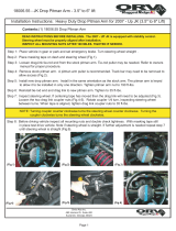
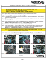
Before working
on a vehicle:
1. Make sure the key-switch is in the “OFF”
position, then remove the key.
2. Place the forward-reverse switch in the
center “OFF” position.
3. Set the park brake.
4. Place blocks under the front wheels to
prevent vehicle movement.
5. Disconnect the main positive and
negative cables at the batteries.
DRIVER TRAINING PROGRAM
According to ANSI B56.8, the owner of this vehicle shall
conduct an Operator Training program for all those who
will be operating this vehicle. The training program shall
not be condensed for those claiming to have previous
vehicle operation experience. Successful completion of
the Operator Training program shall be required for all
personnel who operate this vehicle.
The Operator Training program shall include the
following:
Operation of this vehicle under circumstances
normally associated with your particular environment.
Emphasis on the safety of cargo and personnel.
All safety rules contained within this manual.
Proper operation of all vehicle controls.
A vehicle operation and driving test.
Driver Qualifications.
Only those who have successfully completed the
Operator Training program are authorized to drive this
vehicle. Operators must possess the visual, auditory,
physical, and mental ability to safely operate this vehicle
as specified in the American National Standards Institute
Controlled Personnel and Burden Carriers ANSI B56.8.
The following are minimum requirements necessary to
qualify as an operator of this vehicle:
Demonstrate a working knowledge of each control.
Understand all safety rules and guidelines as
presented in this manual.
Know how to properly load and unload cargo.
Know how to properly park this vehicle.
Recognize an improperly maintained vehicle.
Demonstrate ability to handle this vehicle in all
conditions.
SAFETY RULES AND OPERATING INSTRUCTIONS
Safety Rules
Page 4
VEHICLE CONTROLS
Key-Switch
A key-switch, located on the right side of the instrument panel, turns on the
vehicle. Rotate the key clockwise to turn the vehicle power on,
counterclockwise to turn the vehicle power off.
The key-switch should be in the “OFF” position whenever the operator leaves
the driver's seat.
This switch is also designed to secure and disable the vehicle. The key can
only be removed when the key-switch is in the “OFF” position.
Forward-Off-Reverse Switch
The forward-Off-reverse switch, located on the right side of the instrument
panel, determines the direction of travel of the vehicle. Push the top of the
switch to engage the forward direction. Push the bottom of the switch to
engage the reverse direction.
DO NOT SHIFT from forward to reverse or vice-versa while the vehicle is in
motion. Make sure the vehicle is completely stopped before shifting.
The forward-reverse switch should be in the center “OFF” position, with
key-switch off and the park brake set whenever the operator leaves the
driver's seat.
Accelerator Pedal
The accelerator pedal is located to the right of the brake pedal. It controls
the speed of the vehicle and operates similar to the accelerator pedal in an
automobile. Depress the pedal to increase speed and release the pedal to
decrease speed.
Steering
The steering wheel and steering system are similar to an automobile. To
turn right, turn the steering wheel clockwise. To turn left, turn the steering
wheel counter-clockwise.
Foot Brake Pedal
The foot brake pedal, is located to the right of the steering column, it is for
operation with the right foot only. It works similar to the brake in an automobile.
Applying pressure to the brake pedal slows the vehicle according to the
amount of pressure applied. Relieving pressure from the pedal releases the
braking action.
SAFETY RULES AND OPERATING INSTRUCTIONS
Safety Rules
Page 5
The seat interlock switch is only one part of the vehicle safety system.
The interlock switch should not be relied upon as the only safety
feature used to disable or disengage this vehicle. Doing so could result
in unexpected movement of the vehicle causing severe bodily injury
and/or property damage.
Park Brake
The parking brake is actuated with a hand lever, which is located between
the driver and passenger seats. To set the parking brake, push down on the
brake pedal and pull the lever up until it locks. To release the park brake,
depress the foot brake pedal, pull up on the park brake handle, push the
release button, and lower the handle.
Horn Switch
The horn switch is located to the left of the steering column. Depress the
switch with your left foot to sound the horn, release it to turn it off.
Seat Interlock Switch
A switch located under the driver's seat disables the power to the vehicle
when the driver leaves the seat. The driver must be seated for the vehicle
to operate.
Whenever the driver leaves the seat, they should turn the key-switch off,
place the forward-reverse switch in the center “OFF” position, and set the
park brake.
Charger Interlock
The charger interlock is designed to disable the vehicle from being driven
while the AC charger cord is plugged into a functioning power source.
NOTE: The interlock shown is mounted external of the charger. Some vehicles
may have the interlock built into the charger.
SAFETY RULES AND OPERATING INSTRUCTIONS
Safety Rules
Page 6
Headlight Switch
The headlight switch is located on the far left side of the instrument panel.
Push the top of the switch to turn the lighs on. Push the bottom of the switch
to turn the light off.
Reverse or Motion Alarm (Optional)
The reverse alarm is located in the electronics compartment mounted on
the speed control panel or on the rear panel of the vehicle. The reverse
alarm is activated when the Key switch is in the “ON” position and the Forward-
Reverse switch is in the reverse position. The alarm makes a repeated
audible sound.
Electrolyte Alarm (Optional)
The Electrolyte Alarm is located in the battery area, in the 4th battery cell
from the main battery positive cable. The Electrolyte alarm is activated
when the battery cell fluid level falls below the level of the probe. The alarm
is an audible continuous sound along with a bi-color indicator lamp. Inspect
the fluid level in all battery cells when the alarm sounds or the bi-color lamp
turns from its green color to red. The vehicle batteries should then be filled
and/or charged. With the fluid level at a normal operating level and/or the
batteries charged the alarm and light will reset.
Directional Signals (Optional)
The turn signal lever is located on the left side of the steering column.
Push the lever forward to activate the right turn signal and pull the lever
back to activate the left turn signal.
Hazard Light Switch (Optional)
The hazard light switch is located on the left side of the steering column.
The switch is a small tab. To activate the hazard lights, pull the tab out. To
turn the hazard lights off, push forward or pull back the directional signal
lever.
SAFETY RULES AND OPERATING INSTRUCTIONS
Safety Rules
Page 7
Hour Meter (Optional)
The hour meter is located to the right of the battery status indicator. It
records the number of hours the vehicle has been in operation.
Battery Status Indicator, Analog
The battery status indicator is located to the left of the hour meter. The
normal operating range is in the green zone. Park the vehicle for a few
minutes for an accurate reading. The vehicle needs charging if it is in the
yellow zone. During and immediately following charging, the needle will be
in the red zone to the right. The needle will move through the green zone
toward the yellow zone as the batteries discharge. Charge the batteries
when the needle is in the yellow zone. If it is in the red zone to the left, the
batteries are empty and the truck should be taken out of service and charged
to avoid damaging the batteries.
Battery Status Indicator, Digital Bargraph
The battery status indicator is located to the left of the hour meter. The
battery status indicator has a LED bar graph that indicates the relative state
of charge of the battery. The top LED will light only when connected to a fully
charged battery or after completing a charging cycle. Successive lower
LED’s will light as the battery charge diminishes. When the second from the
bottom LED flashes the battery energy status is in energy reserve and should
be placed on charge as soon as possible. When the two bottom LED’s are
alternately flashing the batteries are empty and the truck should be taken
out of service and charged to avoid damaging the batteries. The BSI will
reset to fully charged only after a complete charge cycle is completed. A
complete charge cycle is defined as battery voltage exceeding 2.35 volts
per cell for a minimum of 6 minutes.
SAFETY RULES AND OPERATING INSTRUCTIONS
Safety Rules
Page 8
Smart View Display
The Smart View Display (SVD) functions as a Battery Status Indicator (BSI), Hour Meter (HM), speed controller
status monitor, and as an optional maintenance monitor feature. The operation of each of these functions is described
below.
BSI: A bar graph representing the current state of charge
is located across the top of the display. When the
batteries are fully charged, all segments of the bar graph
will be on. As the batteries are used, segments will turn
off in the order of right to left.
When the batteries are discharged to 75%, the last three
segments will flash indicating that you are approaching
the end of the battery cycle. At this time, the vehicle’s
batteries should be charged as soon as possible.
At 90%, all segments will flash and the vehicles speed
will be reduced. At this time, the vehicle should be
removed from service for charging. Discharging beyond
90% will result in damage to the batteries that will shorten
the battery life-span.
NOTE: The battery status gauge as well as any faults
indicating low battery voltage will not reset
until the batteries have successfully
completed a charging cycle.
HM: Depending on the revision level of the controller,
there are one or two hour meter functions, Key Hours
and Run Time Hours (see note below).
Key Hours is the accumulated length of time in hours
that the key switch is in the “ON” position.
Run Time Hours is the accumulated length of time that
the vehicles has been in operation. Time is accumulated
when the FS-1 switch in the accelerator module is closed.
One of the Hours functions is being displayed whenever
the either of the Hours Indicators are visible at the right
side of the display.
NOTE: The Key Hours function was discontinued
starting with revision K controllers shipped
in 2007.
Key Hours: When the display is turned on, the Key Hours
will be displayed for approximately 5-seconds as
indicated by the Key Hours Indicator located at the lower
left of the display. The icon represents the silhouette of
a key.
Run Time Hours: After the initial 5-seconds, the Run
Time Hours will be displayed as indicated by the Run
Time Hours Indicator located at the left of the display.
The icon represents a motor symbol with a “T” in the
center.
  • Page 1 1
  • Page 2 2
  • Page 3 3
  • Page 4 4
  • Page 5 5
  • Page 6 6
  • Page 7 7
  • Page 8 8
  • Page 9 9
  • Page 10 10
  • Page 11 11
  • Page 12 12
  • Page 13 13
  • Page 14 14
  • Page 15 15
  • Page 16 16
  • Page 17 17
  • Page 18 18
  • Page 19 19
  • Page 20 20
  • Page 21 21
  • Page 22 22
  • Page 23 23
  • Page 24 24
  • Page 25 25
  • Page 26 26
  • Page 27 27
  • Page 28 28
  • Page 29 29
  • Page 30 30
  • Page 31 31
  • Page 32 32
  • Page 33 33
  • Page 34 34
  • Page 35 35
  • Page 36 36
  • Page 37 37
  • Page 38 38
  • Page 39 39
  • Page 40 40
  • Page 41 41
  • Page 42 42
  • Page 43 43
  • Page 44 44
  • Page 45 45
  • Page 46 46
  • Page 47 47
  • Page 48 48
  • Page 49 49
  • Page 50 50
  • Page 51 51
  • Page 52 52
  • Page 53 53
  • Page 54 54
  • Page 55 55
  • Page 56 56
  • Page 57 57
  • Page 58 58
  • Page 59 59
  • Page 60 60
  • Page 61 61
  • Page 62 62
  • Page 63 63
  • Page 64 64
  • Page 65 65
  • Page 66 66
  • Page 67 67
  • Page 68 68
  • Page 69 69
  • Page 70 70
  • Page 71 71
  • Page 72 72
  • Page 73 73
  • Page 74 74
  • Page 75 75
  • Page 76 76
  • Page 77 77
  • Page 78 78
  • Page 79 79
  • Page 80 80
  • Page 81 81
  • Page 82 82
  • Page 83 83
  • Page 84 84
  • Page 85 85
  • Page 86 86
  • Page 87 87
  • Page 88 88
  • Page 89 89
  • Page 90 90
  • Page 91 91
  • Page 92 92
  • Page 93 93
  • Page 94 94
  • Page 95 95
  • Page 96 96
  • Page 97 97
  • Page 98 98
  • Page 99 99
  • Page 100 100
  • Page 101 101
  • Page 102 102
  • Page 103 103
  • Page 104 104
  • Page 105 105
  • Page 106 106
  • Page 107 107
  • Page 108 108
  • Page 109 109
  • Page 110 110
  • Page 111 111
  • Page 112 112
  • Page 113 113
  • Page 114 114
  • Page 115 115
  • Page 116 116
  • Page 117 117
  • Page 118 118
  • Page 119 119
  • Page 120 120
  • Page 121 121
  • Page 122 122
  • Page 123 123
  • Page 124 124
  • Page 125 125
  • Page 126 126
  • Page 127 127
  • Page 128 128
  • Page 129 129
  • Page 130 130
  • Page 131 131
  • Page 132 132
  • Page 133 133
  • Page 134 134
  • Page 135 135
  • Page 136 136
  • Page 137 137
  • Page 138 138
  • Page 139 139
  • Page 140 140
  • Page 141 141
  • Page 142 142
  • Page 143 143
  • Page 144 144
  • Page 145 145
  • Page 146 146
  • Page 147 147
  • Page 148 148
  • Page 149 149
  • Page 150 150
  • Page 151 151
  • Page 152 152
  • Page 153 153
  • Page 154 154
  • Page 155 155
  • Page 156 156
  • Page 157 157
  • Page 158 158
  • Page 159 159
  • Page 160 160
  • Page 161 161
  • Page 162 162
  • Page 163 163
  • Page 164 164
  • Page 165 165
  • Page 166 166
  • Page 167 167
  • Page 168 168
  • Page 169 169
  • Page 170 170
  • Page 171 171
  • Page 172 172
  • Page 173 173
  • Page 174 174
  • Page 175 175
  • Page 176 176
  • Page 177 177
  • Page 178 178
  • Page 179 179
  • Page 180 180
  • Page 181 181
  • Page 182 182
  • Page 183 183
  • Page 184 184
  • Page 185 185
  • Page 186 186
  • Page 187 187
  • Page 188 188
  • Page 189 189
  • Page 190 190
  • Page 191 191
  • Page 192 192
  • Page 193 193
  • Page 194 194
  • Page 195 195
  • Page 196 196
  • Page 197 197
  • Page 198 198
  • Page 199 199
  • Page 200 200
  • Page 201 201
  • Page 202 202
  • Page 203 203
  • Page 204 204
  • Page 205 205
  • Page 206 206
  • Page 207 207
  • Page 208 208
  • Page 209 209
  • Page 210 210
  • Page 211 211
  • Page 212 212
  • Page 213 213
  • Page 214 214
  • Page 215 215
  • Page 216 216
  • Page 217 217
  • Page 218 218
  • Page 219 219
  • Page 220 220
  • Page 221 221
  • Page 222 222
  • Page 223 223
  • Page 224 224
  • Page 225 225
  • Page 226 226
  • Page 227 227
  • Page 228 228
  • Page 229 229
  • Page 230 230
  • Page 231 231
  • Page 232 232
  • Page 233 233
  • Page 234 234
  • Page 235 235
  • Page 236 236
  • Page 237 237
  • Page 238 238
  • Page 239 239
  • Page 240 240
  • Page 241 241
  • Page 242 242
  • Page 243 243
  • Page 244 244
  • Page 245 245
  • Page 246 246
  • Page 247 247
  • Page 248 248
  • Page 249 249
  • Page 250 250
  • Page 251 251
  • Page 252 252
  • Page 253 253
  • Page 254 254
  • Page 255 255
  • Page 256 256
  • Page 257 257
  • Page 258 258
  • Page 259 259
  • Page 260 260

Taylor-Dunn R 380-48 Operator's And Service Manual

Category
Utility Vehicle
Type
Operator's And Service Manual
This manual is also suitable for

Ask a question and I''ll find the answer in the document

Finding information in a document is now easier with AI