Page is loading ...

Goliath PCI Quad
Pentium® Pro
EISA System
User's Guide
MAN-730
6/7/96

Goliath PCI Pentium Pro EISA System User’s Guide
ii
© Copyright 1985-2010 American Megatrends, Inc.
All rights reserved.
American Megatrends, Inc.
5555 Oakbrook Parkway, Building 200,
Norcross, GA 30093
This publication contains proprietary information which is protected by copyright. No part of this publication may be reproduced, transcribed,
stored in a retrieval system, translated into any language or computer language, or transmitted in any form whatsoever without the prior written
consent of the publisher, American Megatrends, Inc.
Limited Warranty
Buyer agrees if this product proves to be defective, that American Megatrends, Inc. is only obligated to replace or refund the purchase price of this
product at American Megatrends’ discretion according to the terms and conditions on the warranty card. American Megatrends shall not be liable
in tort or contract for any loss or damage, direct, incidental or consequential. Please see the Warranty Registration Card shipped with this product
for full warranty details.
Limitations of Liability
In no event shall American Megatrends be held liable for any loss, expenses, or damages of any kind whatsoever, whether direct, indirect,
incidental, or consequential, arising from the design or use of this product or the support materials provided with the product.
Trademarks
Intel and Pentium Pro are registered trademarks of Intel Corporation.
MS-DOS, Microsoft Word, and Microsoft are registered trademarks of Microsoft Corporation. Microsoft Windows, Windows 95, and Windows
NT are trademarks of Microsoft Corporation.
SMC is a registered trademark of SMC Corporation.
IBM, AT, VGA, PS/2, OS/2, and EGA are registered trademarks of International Business Machines Corporation. XT and CGA are trademarks of
International Business Machines Corporation.
Fujitsu is a registered trademark of Fujitsu America, Inc.
Motorola is a registered trademark of Motorola Corporation.
Hitachi is a registered trademark of Hitachi America, Ltd.
PNY is a registered trademark of PNY Corporation.
Oki is a registered trademark of Oki America, Inc.
NEC is a registered trademark of NEC Corporation.
Samsung is a registered trademark of Samsung Electronics Corporation.
Siemens is a trademark of Siemens Corporation.
Mitsubishi is a registered trademark of Mitsubishi Electronics of America.
Micron is a registered trademark of Micron Corporation.
SCO, UnixWare, and Unix are registered trademarks of The Santa Cruz Operation, Inc..
Toshiba is a registered trademark of Kabushiki Kaisha Toshiba.
VESA is a trademark of the Video Electronics Standards Association.
All other brand and product names are trademarks or registered trademarks of their respective companies.
Revision History
5/19/96 Initial release.
6/7/96 Updated for new BIOS release.

Preface iii
Preface
To the OEM Thank you for purchasing the high performance American Megatrends Goliath
EISA system. This product is a state of the art set of CPU cards, memory card,
and a baseboard that includes the famous AMIBIOS. It is assumed that you
have also licensed the rights to use the American Megatrends documentation
for the American Megatrends Goliath.
This manual was written for the OEM to assist in the proper installation and
operation of this product. This manual describes the specifications and features
of the Goliath system. It explains how to assemble a system based on the
Goliath system and how to use the AMIBIOS that is specifically designed for
this system.
This manual is not meant to be read by the computer owner who purchases a
computer with this system. It is assumed that you, the computer manufacturer,
will use this manual as a sourcebook of information, and that parts of this
manual will be included in the computer owner's manual.

Goliath PCI Pentium Pro EISA System User’s Guide
iv
Technical Support
If you need help installing, configuring, or running this product, call American
Megatrends technical support at 770-246-8645. You can also send questions to
tech support at:

Preface v
Packing List
You should have received the following:
• a Goliath baseboard,
• a Series 731 CPU 1 card,
• a Series 732 CPU 2 card or a Series 733 terminator card,
• a Series 741 memory card,
• a U-shaped bracket with screws and spacers to be attached to the S730
baseboard, the CPU 2 card, and the memory card,
• a customized PS/2 mouse cable,
• two customized serial cables,
• one customized parallel cable,
• a Warranty Card, and
• the American Megatrends Goliath Pentium Pro EISA System User's Guide.
Static Electricity
The Goliath baseboard, CPU cards, and memory card can easily be damaged by
static electricity. Make sure you take appropriate precautions against static
electric discharge:
• wear a properly-grounded wristband while handling the Goliath system or
any other electrical component,
• touch a grounded anti-static surface or a grounded metal fixture before
handling the Goliath system,
• handle system components by the mounting bracket, if possible.
Batteries Make sure you dispose of used batteries according to the battery manufacturer’s
instructions. Improper use of batteries may cause an explosion. Make sure you
follow the battery manufacturer’s instructions about using the battery. Replace
used batteries with the same type of battery or an equivalent recommended by
the battery manufacturer.

Chapter 1 Hardware Installation
1
1 Hardware Installation
Features
The American Megatrends Goliath Quad Pentium Pro™ EISA PCI system
supports one to four Intel® Pentium Pro CPUs operating at 180 MHz or higher
speeds.
Components The Goliath consists of several components:
• a baseboard that includes the EISA and PCI expansion slots and most of
the electronics,
• a primary and a secondary CPU Card. Each CPU Card can have 1 or 2
Pentium Pro CPUs,
• A Terminator Card (used only if the second CPU Card is not installed),
and a
• memory card.
The Goliath system was designed to run with the memory card and both CPU
Cards installed on the baseboard. However, the second CPU Card does not have
to be installed if a Series 733 GTL terminator is installed in J8, the CPU Card 2
connector.
CPUs The Pentium Pro CPUs are mounted on two separate CPU Cards for easy CPU
upgrades. Each CPU card holds one or two Pentium Pro CPUs. All Intel
Pentium Pro CPUs use 3.3V.
System Memory The Goliath system supports up to 1 GB of onboard system memory through
eight 8 DIMM sockets. This system supports four-way interleaved memory
operation for maximum performance. The system supports 168-pin DIMMs.
The system memory supports ECC (Error Checking and Correction).
Cont’d

Goliath PCI Pentium Pro EISA System User’s Guide
2
Features, Continued
Cache Memory The Goliath system provides 256 KB or 512 KB of cache memory internal to
each Pentium Pro CPU.
EISA ExpansionThe Goliath baseboard includes four EISA expansion slots. All EISA expansion
slots can handle full-length EISA adapter cards.
PCI Local Bus The Goliath baseboard has six PCI expansion slots on two peer PCI buses using
dual OPBs (Orion PCI Bridge) and totally independent parallel PCI operation
on two peer PCI buses. The buses can transfer data simultaneously at a
maximum rate of 132 MBs.
All PCI slots are bus master slots and comply with the PCI Version 2.0
specification. All PCI expansion slots except the Primary PCI 3 slot can handle
full-length PCI adapter cards.
Integrated I/O The Goliath baseboard provides the following integrated I/O:
• one bidirectional parallel port that operates in Normal, EPP, or ECP mode,
• two serial ports with 16550A UARTs,
• one floppy drive controller with support for 360 KB, 720 KB, 1.2 MB, 1.44
MB, and 2.88 MB floppy drives,
• support for up to two Enhanced IDE drives on the PCI local bus,
• a berg header for a PS/2 mouse cable, and
• a standard DIN keyboard connector.
Cont’d

Chapter 1 Hardware Installation
3
Features, Continued
Power Monitors The Goliath baseboard includes power monitor that make sure all power lines
are stable before the CPUs are started. The onboard voltage monitors check all
voltages and provide a warning if power is about to fail.
IDE Features IDE support on the Goliath baseboard includes:
• supports up to 2 IDE drives on the local bus,
• supports IDE programmed I/O (PIO) modes 3 and 4,
• provides bus mastering IDE support,
• provides IDE on the local bus,
• supports 32-bit data transfers,
• provides Fast ATA support, and
• supports LBA and Block Mode.
AMIBIOS AMIBIOS includes a PCI BIOS with WINBIOS Setup in flash ROM. Features
include:
• automatic CPU detection,
• Plug and Play NVRAM,
• PCI-PCI bridge support,
• DMI support,
• ATAPI support for IDE CD-ROM drives,
• ability to boot from a CD-ROM drive,
• complies with the Intel NSP specification,
• automatically detects IDE drive parameters,
• supports Enhanced IDE, including support for 2 IDE drives,
• supports ATA IDE mode programming,
• provides LBA and Block Mode support,
• provides boot sector virus protection,
• automatically detects and configures system memory, cache memory, and the CPU
type,
• automatically configures PCI devices, and
• complies with the Plug and Play Version 1.0A BIOS specification.
Cont’d

Goliath PCI Pentium Pro EISA System User’s Guide
4
Features, Continued
PCI Bus Speed The Goliath system conforms to the PCI Version 2.0 specification. The PCI
slots are automatically configured by the AMIBIOS. The PCI slots operate
synchronously with the CPU clock, as follows:
CPU External Clock Frequency PCI Expansion Slot Frequency
66 MHz 33 MHz
60 MHz 30 MHz
Goliath Dimensions
The full-size AT Goliath baseboard is approximately 12” by 13.1”. The Series
732 CPU Card 2 is 13” long and 6” high. The Series 731 CPU Card 1 is 7”
long by 6” high. The Series 741 Memory Card is 6.25” long and 6” high.
CPU Card 1
CPU Card 2
Memory Card
Bolt the Memory Card to the steel
bracket with a plastic spacer between
the bracket and the Memory Card.
Bolt the memory card
to the steel U bracket
with a plastic spacer
between the bracket
and the memory card.
Secure the U bracket to the
baseboard using the
screw and nut pair.

Chapter 1 Hardware Installation
5
Installation Steps
Step Action
1 Unpack the baseboard and associated adapter cards.
2 Configure the CPU.
Configure the CPU.
Set the Clock Ratio.
Configure CPU Card 1.
Configure CPU Card 2.
Install the CPU.
3 Install memory.
Install system memory.
4 Install the baseboard.
5 Attach cables to connectors.
Connect the power supply.
Attach the keyboard cable.
Connect the mouse cable.
Attach connector cables.
6 Connect the serial ports.
7 Connect the parallel port.
8 Connect floppy drives.
9 Connect the IDE drive(s).
10 Test and configure.
Warning
This baseboard contains sensitive electronic
components that can be easily damaged by static
electricity. Follow the instructions carefully to
ensure correct installation and to avoid static
damage.

Goliath PCI Pentium Pro EISA System User’s Guide
6
Goliath Baseboard Layout
The Denotes Pin 1 in Jumpers and Connectors.
J26
J9 KEBD
J5
Ser1
P10 PCI SLOT 2
PCI SLOT 4
P1
P
5
J20
J21
J16
Real Time Clock
J29
HLED
J27
RESET
J28
SPKR
T
h
e
p
o
i
n
t
s
t
o
w
a
r
d
P
i
n
1
.
P10 PCI SLOT 1
P12 PCI SLOT 3
PCI SLOT 5
PCI SLOT 6
J
2
I
DE
J10 Mouse
J6
Ser2
J7
LPT1
P2
P4
P3
J3
Floppy
P6
J11
J12
J19
J18
J24
J23
J15
J17
J4
Series 730 Rev-C Goliath
(C) 1996 American Megatrends
J22
KBD
Lock
J25
Ext
SMI

Chapter 1 Hardware Installation
7
Goliath Terminator Card Layout
Goliath Memory Card Layout
Bank1
Bank2
DRAM Module1
DRAM Module2
DRAM Module3
DRAM Module4
DRAM Module5
DRAM Module6
DRAM Module7
DRAM Module8
Avoid Static Electricity
Static electricity can damage the baseboard and other computer components.
Keep the baseboard in the anti-static bag until it is to be installed. Wear an
anti-static wrist grounding strap before handling the baseboard. Make sure you
stand on an anti-static mat when handling the baseboard. Avoid contact with
any component or connector on any adapter card, printed circuit board, or
memory module. Handle these components by the mounting bracket.

Goliath PCI Pentium Pro EISA System User’s Guide
8
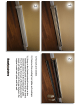
Step 1 Unpack the Boards
The Goliath system includes the following components:
AMI Part
Number
Description
Series 730 Baseboard
Series 731 CPU I Card (has 1 or 2 Pentium Pro CPUs)
Series 732 CPU 2 Card (has 1 or 2 Pentium Pro CPUs)
Series 733 GTL terminator (only used if Series 732 CPU
2 Card is not installed)
Series 741 Memory Card (8 rows of DIMM DRAM
modules).
Step Action
1 Inspect the cardboard carton for obvious damage. If damaged,
call 770-246-8645. Leave the baseboard in its original packing.
2 Perform all unpacking and installation procedures on a ground-
connected anti-static mat. Wear an anti-static wristband
grounded at the same point as the anti-static mat. Or use a
sheet of conductive aluminum foil grounded through a 1
megohm resistor instead of the anti-static mat. Similarly, a
strip of conductive aluminum foil wrapped around the wrist
and grounded through a 1 megohm resistor serves the same
purpose as the wristband.
3 Inside the carton, the baseboard is packed in an anti-static bag,
and sandwiched between sheets of sponge. Remove the sponge
and the anti-static bag. Place the baseboard on a grounded
anti-static surface component side up. Save the original
packing material.
4 Inspect the baseboard for damage. Press down on all ICs
mounted in sockets to verify proper seating. Do not apply
power to the baseboard if it has been damaged.
5 If the baseboard is undamaged, it is ready to be installed.
Set Jumpers Set all jumpers and install the CPU before placing the baseboard in the chassis.

Chapter 1 Hardware Installation
9
Step 2 Configure CPU
Important
Perform the following steps to configure the
baseboard before installing a CPU.
Compatible Mode J4 is an eight-pin berg on the baseboard that sets the compatibility mode.
Leave J4 OPEN.
APIC Mode J17 is a 3-pin berg that sets the APIC (Advanced Programmable Interrupt
Controller) mode. Always Short Pins 2-3 of J17.
External Clock J16 is a 6-pin berg on the baseboard that sets the PCI external bus clock speed.
The primary and secondary PCI clock is set to 30 MHz or 33 MHz by a /2
synchronous divisor.
External
PCI Clock
Speed
J16 CPU Internal
Speed
Internal PCI
Speed
60 MHz Short Pins 1-2
Short Pins 5-6
150 MHz
180 MHz
30 MHz
66 MHz Short Pins 3-4 200 MHz 33 MHz
Cont’d

Goliath PCI Pentium Pro EISA System User’s Guide
10
Step 2 Configure CPU, Continued
CPU Clock Ratio J15 is an 8-pin berg on the Series 730 baseboard that sets the CPU clock ratio
for the Series 731 CPU Card 1.
J190 is an 8-pin berg on the Series 730 baseboard that sets the CPU clock ratio
for the Series 732 CPU Card 2.
If two CPUs are installed on a CPU Card, the CPUs must operate at the same
speed.
In Rev C of the baseboard, CPU Card 1 and CPU Card 2 can be set to different
internal clock ratios.
J15 for CPU Card 1
J190 for CPU Card 2
Ratio External CPU
Speed
Internal CPU
Speed
Short Pins 1-2
Short Pins 3-4
Short Pins 5-6
Short Pins 7-8
2:1 66 MHz 133 MHz
Short Pins 1-2
Short Pins 3-4
Short Pins 5-6
3:1 60 MHz 180 MHz
Short Pins 1-2
Short Pins 3-4
Short Pins 5-6
3:1 66 MHz 200 MHz
Short Pins 1-2
Short Pins 3-4
Short Pins 7-8
5:2 60 MHz 150 MHz
Short Pins 1-2
Short Pins 3-4
7:2 66 MHz 233 MHz
Short Pins 3-4
Short Pins 5-6
Short Pins 7-8
4:1 60 MHz 240 MHz
Short Pins 3-4
Short Pins 5-6
5:1 60 MHz 300 MHz
Short Pins 3-4
Short Pins 7-8
9:2 66 MHz 283 MHz
Short Pins 3-4 11:2 60 MHz 325 MHz
Cont’d

Chapter 1 Hardware Installation
11
Step 2 Configure CPU, Continued
Configure CPU Card 1 You can install either one or two Pentium Pro CPUs in the ZIF sockets
on CPU Card 1. The CPU external and internal clock speeds are set via J15 on
the baseboard, as described on the previous screen. JP3 must always have a
shorting bridge.
Set VRM Output J1 on the CPU Cards set the VRM output for the first CPU. J2 sets the VRM
output for the second CPU. For a 3.3V CPU, short Pins 1-2, Pins 5-6, and Pins
7-8.
CPU Fans JP1 (for the first CPU) and JP2 (for the second CPU) are the +12V connectors
for the cooling fans. The CPU fan cable must be connected to one of these
connectors. Pin 1 of JP1 and JP2 is +12V. Pin 2 is Ground.
CPU Power Module The CPU Cards include two sockets for the two CPU power modules.
VRM8 is Voltage Regulator Module 8. VRM works from 5V input.
CPU Card Layout The CPU Card 1 layout is shown below.
Cont’d

Goliath PCI Pentium Pro EISA System User’s Guide
12
Step 2 Configure CPU, Continued
Configure CPU Card2 You can install either one or two Pentium Pro CPUs in the ZIF sockets
on CPU Card 2. The CPU external and internal clock speeds are set via J190 on
the baseboard. Both CPUs are configured in the same manner.
Set VRM Output J1 on the CPU Cards set the VRM output for the first CPU. J2 sets the VRM
output for the second CPU. For a 3.3V CPU, short Pins 1-2, Pins 5-6, and Pins
7-8.
CPU Fans JP1 (for the first CPU) and JP2 (for the second CPU) are the +12V connectors
for the cooling fans. The CPU fan cable must be connected to one of these
connectors. Pin 1 of JP1 and JP2 is +12V. Pin 2 is Ground.
CPU Power Module The CPU Cards include two sockets for the two CPU power modules.
VRM8 is Voltage Regulator Module 8. VRM works from 5V input.
CPU Card 2 Layout
Cont’d

Chapter 1 Hardware Installation
13
Step 2 Configure CPU, Continued
JP3 This jumper on the Series 731 CPU Card 1 should always be shorted.
Overheat LEDs The Goliath CPU Cards have two red LEDs (one for each CPU) that indicate if
the CPU is overheating. A buzzer on the CPU Cards also sounds a warning if
the CPUs are overheating.
Important
Turn the computer off as soon as possible if an overheat
LED is lit. Operating the computer when this LED is on
can permanently damage the computer. Make sure that
the problem that caused the CPU to overheat is
corrected before you turn the computer on again.
The most frequent cause of overheating is a non-working CPU fan or a
disconnected CPU fan.
Install CPUs Install the Pentium Pro CPUs in the ZIF (zero insertion force) socket on the
CPU Card as shown below.
Do not install the CPU Card in the baseboard until after the CPUs are installed.
Both CPU Cards should be installed even if only one CPU Card includes a
mounted CPU. Each CPU Card can have either one or two Intel Pentium Pro
CPUs. Both CPUs on a CPU Card must run at the same frequency.
Warning
Improper CPU installation can damage the CPU,
the CPU Card, and the baseboard. You must
follow the procedures in this section exactly as
documented. Make sure you wear an antistatic
wristband while installing the CPU.
Cont’d

Goliath PCI Pentium Pro EISA System User’s Guide
14
Step 2 Configure CPU, Continued
Step Action
1 Lift the lever on the ZIF socket. The empty CPU socket
looks like this.
2 Check for bent pins on the CPU. Gently straighten any bent
pins with pliers. Place the CPU in the middle of the socket,
as shown below. Make sure that pin 1 of the CPU is aligned
with pin 1 of the socket. Make sure you are properly
grounded while handling the CPU.
3 Lift the ZIF lever to the other side of the socket. Close the
handle until it latches.

Chapter 1 Hardware Installation
15
Step Action
4 Install the fan/heat sink and press down. The installed CPU
fan and heat sink will appear as follows.
I
n
t
e
l
u
I
n
t
e
l
u
5 Attach the fan cable to the appropriate fan connector (JP1 for
the first CPU or JP2 for the second CPU). Latch the CPU
clip on both sides to the tabs on the CPU socket.
6 Install the voltage regulator (VRM module) in the socket
above each installed CPU, as shown below:
Cont’d
/