Moxa IMC-101 Series Quick setup guide
- Category
- Network switches
- Type
- Quick setup guide
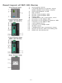
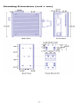
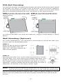
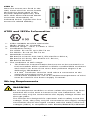
Moxa IMC-101 Series industrial media converters are ideal for harsh environments, offering reliable conversion between copper and fiber networks. Key features include auto-negotiation and MDI/MDI-X for easy integration, support for multi-mode and single-mode fiber, Link Fault Pass-Through for network resilience, relay output alarm for fault notification, redundant power inputs for high availability, and a wide operating temperature range for flexible deployment.
Moxa IMC-101 Series industrial media converters are ideal for harsh environments, offering reliable conversion between copper and fiber networks. Key features include auto-negotiation and MDI/MDI-X for easy integration, support for multi-mode and single-mode fiber, Link Fault Pass-Through for network resilience, relay output alarm for fault notification, redundant power inputs for high availability, and a wide operating temperature range for flexible deployment.


-
 1
1
-
 2
2
-
 3
3
-
 4
4
-
 5
5
-
 6
6
-
 7
7
-
 8
8
-
 9
9
-
 10
10
-
 11
11
-
 12
12
-
 13
13


Moxa IMC-101 Series Quick setup guide
- Category
- Network switches
- Type
- Quick setup guide
Moxa IMC-101 Series industrial media converters are ideal for harsh environments, offering reliable conversion between copper and fiber networks. Key features include auto-negotiation and MDI/MDI-X for easy integration, support for multi-mode and single-mode fiber, Link Fault Pass-Through for network resilience, relay output alarm for fault notification, redundant power inputs for high availability, and a wide operating temperature range for flexible deployment.
Ask a question and I''ll find the answer in the document
Finding information in a document is now easier with AI
Related papers
-
Moxa IMC-101-M-SC Installation guide
-
-
-
-
-
-
-
 Moxa Technologies PTC-101 Series Quick Install Guide
-
-

Other documents
-
 Novartis IMC-101 User manual
-
Moxa Technologies EDS-208 User manual
-
Intellisystem IT-ES308-IU-4F Owner's manual
-
-
Lantronix XPress-Pro SW Quick start guide
-
-
 Moxa Technologies EDS-309 Installation guide
-
 Moxa Technologies EDS-309 Installation guide
-
 Moxa Technologies ETHERDEVICE EDS-305 User manual
-
ICP NS-206AFCS-T User manual


