Cloud LE-1 Installation Guide.pdf Installation guide
- Category
- Musical Equipment
- Type
- Installation guide

LE-1
Remote Line Input Plate
Installation Guide
Cloud Electronics Limited
140 Staniforth Road, Shefeld. S9 3HF. England
Tel: +44 (0)114 244 7051 Fax: +44 (0)114 242 5462
email: [email protected].uk web: www.cloud.co.uk
Introduction
The LE-1 is a remote line input plate for use with the Cloud DCM-1 Digitally Controlled
Mixer, and cannot be used with any other Cloud product. This document provides
information on how to connect LE-1s into a DCM-1-based audio system. Further
information on conguring the DCM-1 itself for use with LE-1s can be found in the
DCM-1 Installation and User Guide.
The LE-1 allows a stereo unbalanced line-level audio source, such as a portable music
centre, laptop, radio mic receiver or similar to be connected into a DCM-1-based audio
system.

LE-1 Installation Guide v1.02
Introduction - continued
Two types of input connector are provided: dual phono sockets for line level signals
with a nominal level of 0dBu), and a 3.5mm stereo jack socket for higher level signals
(approx. +8dB nominal), such as are found at the headphone output sockets of portable
audio devices. Gain trim adjustment (±12dB) is available on the faceplate, and a red
“Peak” LED illuminates when an input signal exceeds nominal level. The gain should
be adjusted so that the LED illuminates briey only on the loudest sections of audio
programme.
Mounting - mechanical
The Cloud LE-1 ts a standard dual-gang electrical back box. The back box used should
have a depth of at least 35mm (1.25”). Note that the LE-1 is made in various faceplate
sizes to suit standard electrical plate sizes in use in the UK, USA and Australia; ensure
you have the correct version for your territory.
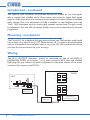
Wiring
The LE-1’s OUTPUT connector should be connected to one of the DCM-1’s
EXTENSION PORTs (Line inputs 1 to 4) with screened CAT-5 cable and shielded
RJ45 plugs. Do not connect any other equipment to the phono sockets of the same-
numbered Line Input on the DCM-1.
Connect to
Output socket
Screened
CAT-5 cable
LE-1
OUTPUT
LINK
Microphone Inputs
Extension Ports
DCM-1
1
2
3
4
1
2
3
4
Connect to an
unused Extension Port

LE-1 Installation Guide v1.0 3
Note that because the cables carry low-level audio, only screened CAT-5 should be
used, the foil screen of the cable being bonded to the metal screening can of the plugs.
If an LE-1 is being mounted in close proximity to the DCM-1, it may be possible to
use ready-made screened CAT-5 “patch” cables of an appropriate length. Otherwise,
shielded RJ45 plugs should be crimped onto the installed screened CAT-5 cable using
the pinout shown below.
PIN USE CAT-5 CORE
1 Left (cold) White + Orange
2 Left (hot) Orange
3 Sense White + Green
4 DC +ve Blue
5 0v White + Blue
6 DC -ve Green
7 Right (hot) White + Brown
8 Right (cold) Brown
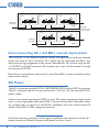
Connecting Multiple LE-1s
Multiple LE-1s may be “daisy-chained” together to provide input points at different
locations in the same zone. Signals applied to plates wired in this way will be summed
together to the DCM-1 Line Input to which the “last” LE-1 in the chain is connected.
An internal gating circuit on each plate automatically “disconnects” any chained plates
which are not in use, to minimise noise contribution. Chained plates will be treated as
a single line input at the DCM-1.
Multiple LE-1s in the same zone may be daisy-chained by connecting the LINK RJ45
socket on the rst LE-1 (that whose OUTPUT socket is connected directly to the
DCM-1) to the OUTPUT socket on the second LE-1, and so on, as shown on page 4.
1
8
1
8
1
8
1
8

LE-1 Installation Guide v1.04
LE-1
OUTPUT
LINK
LE-1
OUTPUT
LINK
LE-1
OUTPUT
LINK
LE-1
OUTPUT
LINK
LE-1
OUTPUT
LINK
To DCM-1
Extension Ports
(one per zone).
ZONE 1
ZONE 2
Additional
input plates
Additional
input plates
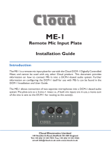
Interconnecting LE-1 and BE-1 remote input plates
The Cloud BE-1 is an alternative optional remote line input plate, providing a balanced
stereo line input on XLR connectors. LE-1 plates may be intermixed with BE-1s in a
daisy-chain wiring arrangement in the manner described for LE-1s alone, using the BE-
1’s OUTPUT and LINK connectors. All the plates on a chain will be treated as a single
line input at the DCM-1.
Note that is not possible to intermix LE-1s with Cloud ME-1 remote microphone input
plates in this manner.
DC Power
The LE-1 is powered from the DCM-1’s EXTENSION PORTs via the CAT-5 connection.
The LE-1 consumes 22mA of current on both the +12V and -12V rails from the DCM-1
power supply.
If there is any doubt regarding the DCM-1’s spare DC power capacity (as might be the
case in a very large system with many CDR-1 remote controls, level restoration relays,
etc.), please refer to page 53 of the DCM-1 Installation and User Guide where full
details of the DCM-1’s PSU ratings can be found.
Should you have any questions concerning the installation and connection of the LE-1,
please contact our Technical Support staff (details on front cover).
-
 1
1
-
 2
2
-
 3
3
-
 4
4


Cloud LE-1 Installation Guide.pdf Installation guide
- Category
- Musical Equipment
- Type
- Installation guide
Ask a question and I''ll find the answer in the document
Finding information in a document is now easier with AI
Related papers

Other documents
-
 Cloud B Microphone ME-1 User manual
-
 Andrew Node G 930 User manual
-
Toyota Camry Owner's manual
-
Toyota Sequoia Owner's manual
-
-
SP Controls PixiePlus ELPSP10 Installation guide
-
-
Toyota C-HR Owner's manual
-
-

