Page is loading ...

THANK YOU
We appreciate the trust and condence you have placed in Commercial Electric through the purchase of this
emergency light. We strive to continually create quality products designed to enhance your home. Visit us online to see
our full line of products available for your home improvement needs. Thank you for choosing Commercial Electric!
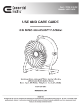
USE AND CARE GUIDE
DUAL COLOR LED EXIT SIGN
Questions, problems, missing parts? Before returning to the store,
call Commercial Electric Customer Service
8 a.m. - 7 p.m., EST, Monday - Friday, 9 a.m. - 6 p.m., EST, Saturday
1-877-527-0313
HOMEDEPOT.COM
Item #1003 821 753
Model #EXLEDRG120277

2
Table of Contents
Safety Information ..................................................... 2
Warranty.....................................................................2
Pre-Installation ..........................................................3
Installation .................................................................5
Maintenance ..............................................................7
Battery Replacement ................................................. 8
Troubleshooting .........................................................8
Safety Information
IMPORTANT SAFEGUARDS. READ AND FOLLOW
ALL SAFETY INSTRUCTIONS.
When using electrical equipment, basic safety precautions should
always be followed including the following:
□ Make all electrical connections in accordance with local
codes, ordinances, and the National Electric Code.
□ This product is for indoor use only.
□ Do not mount this product near a gas or electric heater.
□ Use caution when servicing batteries. Battery acid can
cause burns to skin and eyes. If acid is spilled on skin or
eyes, ush acid with fresh water and contact a physician
immediately.
□ This product should be mounted in a location and at a
height where it will not be readily subjected to tampering
by unauthorized personnel.
□ The use of accessories is not recommended by the
manufacturer, and may cause unsafe conditions.
□ Do not use this product for anything other than its intended
use.
□ All service shall be performed by qualied service
personnel. This product must be installed and maintained
in accordance with the applicable installation codes by
a person familiar with the construction operation of the
product and the hazards involved.
SAVE THESE INSTRUCTIONS
WARNING: Before beginning installation, turn off
electricity by removing the fuse or turning off the circuit
breaker.
WARNING: Disconnect power before servicing the
product. All service should be performed by a qualied
electrician.
WARNING: Changes or modications to this unit
not expressly approved by the party responsible for
compliance could void the user’s authority to operate the
equipment.
NOTICE: This equipment has been tested and found to comply with
the limits for a Class B digital device, pursuant to Part 15 of the FCC
Rules. These limits are designed to provide reasonable protection
against harmful interference in a residential installation. This
equipment generates, uses and can radiate radio frequency energy
and, if not installed and used in accordance with the instructions,
may cause harmful interference to radio communications. However,
there is no guarantee that interference will not occur in a particular
installation. If this equipment does cause harmful interference to
radio or television reception, which can be determined by turning the
equipment off and on, the user is encouraged to try to correct the
interference by one or more of the following measures:
□ Reorient or relocate the receiving antenna.
□ Increase the separation between the equipment and receiver.
□ Connect the equipment into an outlet on a circuit different from
that to which the receiver is connected.
□ Consult the dealer or an experienced radio/TV technician for help.
Warranty
WHAT IS COVERED
The manufacturer warrants this lighting xture to be free from defects in materials and workmanship for a period of ve (5) years,
and ve (5) years for the battery, from date of purchase. This warranty applies only to the original consumer purchaser and only
to products used in normal use and service. If this product is found to be defective, the manufacturer’s only obligation, and your
exclusive remedy, is the repair or replacement of the product at the manufacturer’s discretion, provided that the product has not
been damaged through misuse, abuse, accident, modications, alterations, neglect, or mishandling.
WHAT IS NOT COVERED
This warranty shall not apply to any product that is found to have been improperly installed, set-up, or used in any way not in
accordance with the instructions supplied with the product. This warranty shall not apply to a failure of the product as a result of an
accident, misuse, abuse negligence, alteration, faulty installation, or any other failure not relating to faulty material or workmanship.
This warranty shall not apply to the nish on any portion of the product, such as surface and/or weathering, as this is considered
normal wear and tear.
The manufacturer does not warrant and specically disclaims any warranty, weather express or implied, of tness for a particular
purpose, other than the warranty contained herein. The manufacturer specically disclaims and liability and shall not be liable for
any consequential or incidental loss or damage, including but not limited to any labor / expense costs involved in the replacement or
repair of said product.
Contact the Customer Service Team at 1-877-527-0313 or visit www.HomeDepot.com.

3 HOMEDEPOT.com
Please contact 1-877-527-0313 for further assistance.
Pre-Installation
IMPORTANT: When constructing or remodeling and prior to installing,
be sure to check with the local re marshal or code enforcement ofce to
ensure the correct color guidelines for your municipality are being followed.
PLANNING INSTALLATION
Before beginning assembly, installation, or operation of the product, make sure all parts are present. Compare parts
with the package contents list. If any part is missing or damaged, do not attempt to assemble, install, or operate the
product. Contact customer service for replacement parts.
NOTE: Keep your receipt and these instructions for proof of purchase.
TOOLS REQUIRED
Philips
screwdriver
Wire
strippers
Safety
glasses
Power
drill
Flat
screwdriver
Wire
cutters
Ladder
3/16"
Drill bit
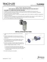
HARDWARE INCLUDED
NOTE: Hardware not shown to actual size.
BB CCAA
DD
Part Description Quantity
AA Canopy screw 2
BB Wire nut 3
CC Wall anchor 2
DD Mounting screw 2

4
Pre-Installation (continued)
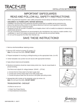
PACKAGE CONTENTS
F
A
G
B
H
C
H
D
E
Part Description Quantity
A Face plate 2
B Exit sign frame 1
C Back plate 1
D Red lens 2
E Green lens 2
F JBOX mounting plate 1
G Canopy 1
H Top/side access cap 2

5 HOMEDEPOT.com
Please contact 1-877-527-0313 for further assistance.
Installation
1
Preparing the exit light
□ Remove the faceplate (A) using a at screwdriver.
□ Remove the appropriate arrow(s) (1) to indicate
the direction of the exit.
□ For double-sided applications, remove the
backplate (C) using a screwdriver and replace
it with the second faceplate (A). Double-sided
applications can only be used with a ceiling or
end mount.
□ Plug in the back-up battery by connecting the
battery lead to the PCB board.
A
1
2
Changing the color (optional)
□ Remove the placard buttons (1) by twisting
them back and forth while pulling up. Remove
the preinstalled red lens.
□ Insert the green lens (E) and replace the placard
buttons by pressing them into place.
□ Move the color selection switch to the “G”
position.
D/E
1
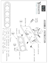
3
Installing the exit sign on a
ceiling or end mount
NOTE: For wall mount applications proceed to Step 4.
□ Remove the top/side mount access caps (H) by
pushing up and out from the underside.
□ Pull the power supply wires from the junction box
through the center hole of the JBOX mounting plate
(F). Attach the JBOX mounting plate (F) to the junction
box using the junction box screws (not included).
□ Feed the xture wires through the appropriate top or
side mounting hole and through the canopy nose.
□ Insert the canopy nose into the mounting hole on the
exit sign frame (B) and lock it into place by rotating
the canopy 90º and sliding to the right, intothe
locking ange, until it locks into place
□ Connect the wiring. Refer to “5 Connecting the
wiring”. Feed the wire nuts back through the center
hole of the JBOX mounting plate (F) into the junction
box.
□ Thread the screws (AA) through the screw holes in
the canopy (G) and attach the canopy to the JBOX
mounting plate (F).
H
AA
G
B
F
H

6
Installation (continued)
4
Installing the exit sign to the
wall
□ Punch out the appropriate mounting pattern and
wire hole on the backplate (C) to t the junction
box. Feed the wires through the wire hole.
□ Connect the wiring. Refer to “5 Connecting the
wiring”.
□ Secure the frame (B) to the junction box using
junction box screws. (Not Included) (1).
C
B
1
5
Installing the exit sign with
conduit
WARNING: This product must be installed in accordance
with the applicable building codes, electric codes and
ordinances. Be sure to comply with your local and state
regulations. It is recommended that this product be
installed be by a licensed electrician or by qualied service
personnel.
□ Route the conduit power supply wires through
the rear of the backplate (C) and make the
conduit connection.
□ Connect the wiring. Refer to “6 Connecting the
wiring”.
□ Using the backplate (C) as a template, mark and
drill two installation holes on the wall at the
desired installation location.
□ Insert wall anchors (CC) into the holes.
□ Attach the backplate (C) to the wall by inserting
screws (DD) through the backplate (C) and into
the wall anchors (CC).
CC
DD
C
B

7 HOMEDEPOT.com
Please contact 1-877-527-0313 for further assistance.
Installation (continued)
6
Connecting the wiring
□ Make wire connections using the wire nuts (BB).
□ For 120 V applications, use the black and white
wires. Connect the black supply wire to the
black xture wire. Connect the white supply
wire to the white xture wire.
□ For 277 V applications, use the red and white
wires. Connect the red supply wire to the red
xture wire. Connect the white supply wire to
the white xture wire.
□ Cap unused wires using a wire nut (BB).
BB
7
Completing the installation
□ Snap the faceplate(s) (A) onto the frame (B).
□ Restore power to the circuit.
□ Allow 24 hours for the back-up battery to fully
charge.
A
B
Maintenance
NOTE: National Electric Code (NEC) and NFPA life safety code
regulations require that routine tests need to be performed.
TESTING OPERATION
With AC Power applied to the unit, the EXIT sign and A/C Power LED indicator should illuminate. When pushing the
TEST button (I), the LED indicator should turn off, the EXIT sign will remain illuminated.
TESTING THE BATTERY
Test the unit’s battery once per month. Additionally, every 12 months, a full 90-minute test should be performed.
While disconnected from the main power supply, the EXIT sign should illuminate for a minimum of 90 minutes on
battery back up power.
TEST
I

8
Battery Replacement
This xture uses a Ni-Cd Rechargeable AA700 mAh 4.8 V battery.
To remove the battery:
□ Bend the battery catches away from the battery and remove the battery from the housing.
□ Disconnect the battery leads from the board terminal.
□ Connect the new battery to the board terminal.
□ Place the new battery in the battery location and ensure it is seated behind the battery catches.
Troubleshooting
Problem Possible Cause Solution
The LED charge indicator
does not illuminate.
AC power supply is off. Ensure the unit has AC power supply. Restore the power
at the breaker/fuse box.
The unit is incorrectly
wired.
Ensure the unit is wired correctly.
The battery isn’t
connected.
Ensure the battery is connected.
If the above troubleshooting does not resolve the issue, contact a qualied electrician, or call Commercial Electric
customer service at 1-877-527-0313.

Questions, problems, missing parts? Before returning to the store,
call Commercial Electric Customer Service
8 a.m. - 7 p.m., EST, Monday-Friday, 9 a.m. - 6 p.m., EST, Saturday
1-877-527-0313
HOMEDEPOT.COM
Retain this manual for future use.
/