Page is loading ...

Multi-Use Extra Tall
Walk-Thru Gate
INSTRUCTION MANUAL
Please read the following instructions carefully.
Keep this instruction manual for future reference.
For technical support, contact us at 1-800-268-6237
or www.summerinfant.com/contact
Tools required: Phillips head screwdriver,
measuring tape (not included),
and wrench (included).
For use with children from 6 - 24 months.
Keep small parts away from children.
Adult assembly required.
Fits openings from 29" - 48" wide.
07060EZ/07970C/07060E
Thank you for purchasing the Multi-Use Extra Tall Walk-Thru Gate from Summer Infant. This gate allows
you to create and maintain a secure environment for your child just about anywhere in your home. It has a
hinged swinging door that opens easily in either direction with one hand, as well as hold-open and
auto-close features for added convenience.

components:
WARNING: FALL HAZARD! IMPORTANT! KEEP FOR FUTURE REFERENCE!
• Children have died or been seriously injured when gate is not securely installed. ALWAYS install and use
gate as directed using all required parts.
• STOP using when a child can climb over or dislodge the gate.
• Use only with the locking/latching mechanism securely engaged.
• To prevent falls, never use at top of stairs without wall mounting cups and door stopper.
• NEVER use to keep child away from pool.
• NEVER leave child unattended.
• Always close and lock the gate behind you.
• This product will not necessarily prevent all accidents.
• Do not use if any components are missing or damaged.
• Adult assembly required. Exercise care when unpacking and assembling product.
IMPORTANT – Read the instructions carefully before use and keep them for future reference.
CAUTION: KEEP SMALL PARTS OUT OF CHILD’S REACH.
Gate Door
Gate Frame
A
B
Small Extension Frame
Large Extension Frame
C
D
Door Stop
Top Latch
E
F
Tension Bolts with Tension Nuts (4)
I
Wall Cups (4)
Adhesive Mounting Pads (4)
J
K
Wall Anchors (4)
L
Lower Latch
Pins (4)
G
H
Screws (4)
M
Wrench
N
hardware:
H
A
E
CD
x4 x4
I
B
2
J K
L M
x4 x4
x4x4
N
x1
F
G

Important: Gate includes a door
stop (part F in components) which
prevents the the gate from swinging
open in one direction. When
installing the gate at the top of stairs,
be sure that the door stop is on the
stairway side of the gate so the door
cannot open over the stairs. While
the door stop comes fully assembled
on gate, it can be removed and
installed on either side of gate frame.
When gate is not used at top of
stairs, door stop may be removed to
allow gate door to open in either
direction.
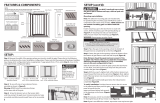
gate configurations (choose which best fits your scenario):
Measure the width of the opening where you intend to install the
gate. Refer to the following illustrations to determine the correct
installation configuration. Baseboard molding may change which
configuration is appropriate.
• If mounting the gate at
top of the stairs, begin
with installation step 1.
• When not used at top
of stairs, begin with
installation step 4.
A
B
D
(29”- 33”) without extension frames
(33.75”- 38”) with small extension frame
(38.75”- 43”) with large extension frame (43.75”- 48”) with small and large extension frames
WARNING:
NEVER install two extension
frames on the same side of the
gate.
!
!
Note: This instruction book illustrates
installation of gate configuration C.
!
3
• If choosing gate configuration A, skip this step.
• If choosing gate configuration B, add the small
extension frame to either side of the gate
frame.
• If choosing gate configuration C, add the large
extension frame to either side of the gate
frame.
• If choosing gate configuration D, add small
extension frame to one side of the gate frame
and large extension frame to the other side of
the gate frame.
C

4
attach
top of the stairs installation:
x 4
x4
x 4
peel
WARNING:
For use at top of stairs, wall cup
installation is MANDATORY.
x 4
peel
x4
1
Follow these wall cup installation instructions when using gate at
TOP OF STAIRS (MANDATORY), or if using wall cups for a
standard opening (optional). If opting not to use wall cups for a
standard opening, move to instructions on next page.
Remove adhesive
protectors from back
of the wall cups as you
apply them to the wall.
35.2”
CENTER HOLE
IN UPPER
WALL CUPS
Stick wall cups onto wall starting with
the bottom cups. The bottom cups
should rest on the floor, the top cups
should be plumb with the bottom cup
with 35.2” distance between the floor
and upper wall cups’ screw hole centers.
3
1
st
2
nd
make sure
all wall cups
are facing up
make sure
all wall cups
are facing up
align
bottom
of wall cups
with floor
align
bottom
of wall cups
with floor
!
!
!
Note: The adhesive mounting
pads are included only for
positioning wall cups and must
be used in conjunction with
screws.
x 4
x 4
Note: If mounting
into plaster walls,
use wall anchors. Using
a 7/32 drill bit, drill a
pilot hole into the wall
in the center of each
wall cup, then insert
wall anchor directly
into wall. Secure the
wall cups in place using
the provided screws.
2
Once Wall Cup
Installation is
complete,
proceed to
Gate Frame
Installation on
next page.
The gate frame's
tension bolts
will nest in
mounting cups.
!
Mounting into plaster or dry wall?
If NO, continue to next step.
!

Connect the
extension frames
to gate frame by
inserting the pins
into the holes
in the gate and
extension
frames.
Slide tension bolts
into upper and lower holes
on both sides of
the gate assembly.
I
x 4
!
• If choosing gate configuration A, skip this step.
• If choosing gate configuration B, add a small gate extension frame to either side of the gate frame.
• If choosing gate configuration C, add the large extension frame to either side of the gate frame.
• If choosing gate configuration D, add small extension frame to one side of the gate frame and large extension
frame to the other side of the gate frame.
4
5
5
installation:
x 4
H
x 4

installation (continued):
The distance between
the gate and the wall
should never exceed
2.75”.
IMPORTANT:
Use the tension nuts
to tighten both of the
bottom tension bolts.
7
6
8
6
Use the tension nuts
to tighten both of the
top tension bolts.
A B
Check distances
A & B. They should
never exceed
2.75”.
Stand the gate in the
center of the opening.
Make sure the bottom of
the gate is completely flat
to the floor. Slide tension
bolts out until they
touch the door frame
or wall.
!
Make sure door stop is facing desired direction.
For top of stair use, door stop must be on stair
side of gate. Gate door must open away from
stairs.
tighten!
tighten!
tighten!
tighten!

installation (continued):
operation:
to unlock gate: hold open feature:
9
N
Close the gate.
Make sure the
upper and lower
latches lock
securely.
!
Tighten the tension
nuts with the
wrench.
FINISHED!
7
Press lock tab
back to release, lift
gate door open.
push!
push!
Push the gate
and frame
to check
stability.
To activate,
open gate door
at least 90º in
either direction.

Please retain information
for future reference.
Colors and styles may vary.
MADE IN CHINA.
4/17 Rev.2
Summer Infant, Inc.
1275 Park East Drive
Woonsocket, RI 02895 USA
1-800-268-6237
© 2016 Summer Infant, Inc.
Summer Infant stands behind all of its products. If you
are not completely satisfied or have any questions,
please contact our Consumer Relations Team at
1-800-268-6237 or www.summerinfant.com/contact
connect with us:
If the gate does not close properly:
1. Gate is not properly aligned in the
door frame.
Solution: Make sure the gate is properly
aligned in the door frame. To adjust the gate’s
alignment, loosen all four tension bolts and
reposition gate so that it matches the “correct”
image. Re-tighten tension nuts.
2. Pressure of tension bolts needs to
be adjusted.
Solution: Loosen or tighten the upper tension
nuts. Ensure the upper latch handle always
remains below the release button. Ensure the
upper latch handle engages securely when the
gate swings closed and that it can be released
properly when the release button is pushed.
troubleshooting:
maintenance:
• Regularly check tension bolts to make sure the gate is securely in place.
• Do not use the gate if any components are damaged or missing.
• Surface clean with a damp cloth or sponge using mild detergent and warm water.
correct!
Make sure
upper latch
handle remains
below release
button!
incorrect!
/