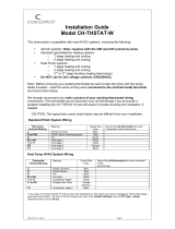
Front Panel Display
The front-panel display shows the current
temperature, setpoint temperature(s), and the
operational status.
A screen with three white dots (
ººº
) on the bottom
of the display indicates that there is a sub-page
available. Press the select button to enter the sub-
page.
Temperature
The DIN-THSTAT displays the current space (indoor) temperature.
Temperature Setpoint(s)
Displays the temperature setpoint(s).
• White setpoint displays for Single-Setpoint Auto mode.
• Red setpoint displays for Heat mode.
• Blue setpoint displays for Cool mode.
• Red and Blue setpoints display for Dual-Setpoint Auto Mode.
System Modes
Displays the current System mode (Off, Heat, Cool, Aux, Auto). Does
not indicate that a system call is being made. For details, refer to the
“Change the System and Fan Mode” section.
Fan Mode
Displays the current Fan mode (AUTO, CIRC, ON). Does not indicate
that a fan call is being made. For details, refer to the “Change the
System and Fan Mode” section.
Calls
Displays the active calls made by the thermostat. There are four
positions on the screen “System Call,” “Fan Call,” “Humidity Call,” and
“Floor Warming Call” (from left to right):
System Call: Cool, Aux Heat, Heat, or None displays in position one
Fan Call: Fan On, Fan Circ, or No Fan displays in position two
Humidity Call: De-Humid, Humidify, or blank displays in position three
Floor Warming Call: Floor Warm or blank displays in position four
Terminals (Y1, Y2, Y3, G, B, O, W1, W2, W3, H, A1, A2)
Light to indicate the relay call state. Displays all of the HVAC system
terminals. Gray indicates that no call is made, colored text that
matches the wire color indicates a call on that terminal.
Comm Status
Displays the current communications status.
Online: The DIN-THSTAT is communicating with the control system.
Offline: The DIN-THSTAT is not communicating with the control system.
Status
Displays errors with readings for the room temperature (INVALID
ROOM TEMP), room humidity (INVALID HUMIDITY), floor temperature
(INVALID FLOOR TEMP), or blank (no error).
Next Event
Displays the name of the upcoming scheduled event.
Change the System and Fan Mode
To change the System mode or Fan mode, navigate to the home screen
and then press the select button. The SYSTEM MODE / FAN MODE
screen displays.
System Mode
To change the System mode, press the left, right, up, and down buttons
to highlight OFF, HEAT, COOL, AUX, or AUTO, and then press the select
button to confirm.
Off Mode: All HVAC systems are disabled.
Heat Mode: The thermostat uses the heating system to maintain the
setpoint temperature.
Cool Mode: The thermostat uses the cooling system to maintain the
setpoint temperature.
Aux Mode: The thermostat uses aux heat only to provide heat. Aux
mode may be required during heat pump servicing or when the heat
pump cannot maintain the setpoint.
Auto Mode: The thermostat allows the HVAC system to switch between
Heat mode and Cool mode automatically to maintain the setpoint
temperature. The thermostat can operate in Dual- or Single-Setpoint
Auto mode.
Select or disable Auto mode during configuration. For configuration
details, refer to the “Configure the DIN-THSTAT” section.
Dual-Setpoint Auto mode:
Dual-Setpoint Auto mode uses separate heat and cool setpoints to
regulate the temperature. When the ambient temperature drops
below the heat setpoint, the unit calls for heat to maintain the
heat setpoint. When the ambient temperature rises above the heat
setpoint, the unit does not call for cooling until the temperature
exceeds the cool setpoint. When the ambient temperature drops
below the cool setpoint, the unit does not call for heating until the
temperature is below the heat setpoint.
The AUTO Deadband setting determines the temperature separation
between the heat and cool setpoints. If a setpoint adjustment
violates this separation, the other setpoint is automatically adjusted.
Single-Setpoint Auto mode:
Single-Setpoint Auto mode uses a single setpoint to regulate the
temperature at all times regardless of whether the HVAC system is
heating or cooling.
The AUTO Deadband setting is used to determine when to switch
between heating and cooling.
For example, the setpoint is at 70° and the AUTO Deadband setting
is 2°, if the system is cooling, it does not start heating until the
ambient temperature drops below 68° (setpoint - AUTO Deadband).
Once the unit has switched to heating, it does not resume cooling
until the ambient temperature rises above 72° (setpoint + AUTO
Deadband).
NOTE: When using Single-Setpoint Auto mode, the DIN-THSTAT uses
a 20-minute change limiter to prevent frequent system toggling.
Changing the setpoint resets the 20-minute change limiter.
Fan Mode
To change the Fan mode, press the left, right, up, and down buttons
to highlight AUTO, CIRC, or ON, and then press the select button to
confirm.
CIRC mode: The fan will maintain a ~30% duty cycle. The duty cycle
includes the time that the fan runs during heat calls and cool calls.
AUTO mode: The fan will turn on when a cool call or heat call is made.
The functionality of the fan during a heat call is determined by the
settings made during configuration of the DIN-THSTAT.
ON mode: When the fan is operating in ON mode, the fan is always on.
Operate the DIN-THSTAT
View and change the basic operating functions of the DIN-THSTAT
using the on-screen display and the HOME, BACK, select, up, down, left,
and right buttons. Values that can be changed are the temperature,
current schedule, humidity, regulations, messages, and device info.
Press the left or right button to navigate to the following screens.
Schedule
The Schedule screen displays the schedule that is currently running, the
current event, and the upcoming event. The control system program
provides the schedule.
The thermostat Schedule mode can be configured to RUN the schedule
programmed on the control system or to HOLD the schedule to prevent
temperature changes from being made.
To change the Schedule mode:
1. Press the select button. The SCHEDULE MODE screen is
displayed.
2. Press the left or right button to highlight RUN or HOLD, and then
press the select button to confirm.
3. Press the BACK button to return to the previous screen.
When the system exits Hold mode, the system activates the schedule
that is desired for that time.
Humidity
The Humidity screen displays the current and desired humidity level.
To change the humidity setpoint, press the up or down button to select
a value.
To enable or disable Humidifier mode:
1. Press the select button. The HUMIDIFIER MODE screen is
displayed.
2. Press the left or right button to highlight ENABLE or DISABLE,
and then press the select button to confirm.
3. Press the BACK button to return to the previous screen.
Regulation
The Regulation screen displays the Space and Outdoor temperature
and humidity readings and the Floor temperature reading. If the sensor
connected to TS1 and TS2 are both configured as Space sensors, the
value displayed is the average of the two sensor readings.
To view the temperature and humidity readings of all connected
sensors, press the select button. The SENSORS screen is displayed.
Press the BACK button to return to the previous screen.
Radiant Floor
The Radiant Floor screen displays the current floor temperature and
the desired floor temperature setpoint.
NOTE: The Radiant Floor screen is displayed when the radiant floor
type is set to Floor Warming or space heating.
To change the floor temperature setpoint, press the up or down button
to select a value.
To enable or disable Radiant Floor mode:
1. Press the select button. The RADIANT FLOOR MODE screen is
displayed.
2. Press the left or right button to highlight ON or OFF, and then
press the select button to confirm.
3. Press the BACK button to return to the previous screen.
Message
The Message screen displays essential system messages.
Device Info
The Device Info screen displays the device information such as the
firmware version, serial number, and HW version.
The Device Info screen also provides access to the configuration menu
on the DIN-THSTAT. For configuration details, refer to the “Configure
the DIN-THSTAT” section below.
Configure the DIN-THSTAT
Configure the DIN-THSTAT to match the connected HVAC system and
the usage requirements of the thermostat. Configure the DIN-THSTAT
using the Thermostat Configuration Tool in Crestron Toolbox™
software or using the front-panel controls.
CAUTION: Only qualified personnel should make changes to the
settings on the following page. Damage to the DIN-THSTAT and HVAC
system may occur if incorrect settings are selected.
To configure the DIN-THSTAT:
1. Press the left or right button to navigate to the Device Info
screen.
2. Press the select button to enter the Gateway To Config screen.
3. Press and hold the select button.
4. While holding the select button, press and hold the up and down
buttons for 5 seconds. The configuration warning screen displays.
5. Press the select button to enter the configuration menu or press
the HOME button to exit the configuration menu.
NOTE: The DIN-THSTAT restarts after exiting the configuration
menu.
6. Configure the DIN-THSTAT as necessary. To navigate the
configuration menu:
• Press the left or right buttons to navigate through the setup
screens.
• Press the up or down buttons to highlight items on the page,
and then press the select button to change the value.
• When the item is highlighted in red, press the up or down
buttons to change the value.
• Press the select button to confirm the selected value and
return to the previous page.
To configure the DIN-THSTAT, refer to the DIN-THSTAT Supplemental
Guide (Doc. 8318) at www.crestron.com/manuals.
Additional Information
Scan or click the QR code for detailed product information.
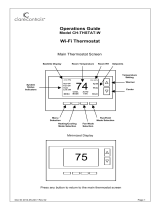
DIN-THSTAT
CRESTRON
System: Auto Fan Mode: Auto
Calls:
Heat Fan
Y1 Y2 Y3 G B O W1 W2 W3 H A1 A2
Comm Status: Oline
Status: OK
Next Event: -
68
72
74
Compliance and Legal
Federal Communications Commission (FCC) Compliance Statement
This device complies with part 15 of the FCC Rules. Operation is subject to the following
conditions: (1) This device may not cause harmful interference and (2) this device must accept
any interference received, including interference that may cause undesired operation.
CAUTION: Changes or modifications not expressly approved by the manufacturer responsible
for compliance could void the user’s authority to operate the equipment.
NOTE: This equipment has been tested and found to comply with the limits for a Class B
digital device, pursuant to part 15 of the FCC Rules. These limits are designed to provide
reasonable protection against harmful interference in a residential installation. This
equipment generates, uses and can radiate radio frequency energy and, if not installed
and used in accordance with the instructions, may cause harmful interference to radio
communications. However, there is no guarantee that interference will not occur in a
particular installation. If this equipment does cause harmful interference to radio or
television reception, which can be determined by turning the equipment off and on, the user is
encouraged to try to correct the interference by one or more of the following measures:
• Reorient or relocate the receiving antenna.
• Increase the separation between the equipment and receiver.
• Connect the equipment into an outlet on a circuit different from that to which the
receiver is connected.
• Consult the dealer or an experienced radio/TV technician for help.
Industry Canada (IC) Compliance Statement
CAN ICES-3 (B)/NMB-3(B)
The product warranty can be found at www.crestron.com/warranty.
The specific patents that cover Crestron products are listed at
www.crestron.com/legal/patents.
Certain Crestron products contain open source software. For specific information, please visit
www.crestron.com/opensource.
Crestron, the Crestron logo, and Cresnet are either trademarks or registered trademarks
of Crestron Electronics, Inc. in the United States and/or other countries. Other trademarks,
registered trademarks, and trade names may be used in this document to refer to either the
entities claiming the marks and names or their products. Crestron disclaims any proprietary
interest in the marks and names of others. Crestron is not responsible for errors in typography
or photography.
©2019 Crestron Electronics, Inc.
Crestron Electronics, Inc.
15 Volvo Drive, Rockleigh, NJ 07647
Tel: 888.CRESTRON
Fax: 201.767.7576
www.crestron.com
Quick Start - Doc. 8317B
(2051468)
06/24/19
Specifications su
bject to
change without notice.