Page is loading ...

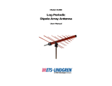
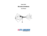
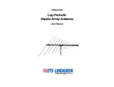
Model 3149
BiConiLog™ Antenna
User Manual

ii |
ETS-Lindgren Inc. reserves the right to make changes to any products herein to
improve functioning or design. Although the information in this document has
been carefully reviewed and is believed to be reliable, ETS-Lindgren does not
assume any liability arising out of the application or use of any product or circuit
described herein; nor does it convey any license under its patent rights nor the
rights of others. All trademarks are the property of their respective owners.
© Copyright 2003–2021 by ETS-Lindgren Inc. All Rights Reserved. No part
of this document may be copied by any means without written permission
from ETS-Lindgren Inc.
Trademarks used in this document: The ETS-Lindgren logo is a registered
trademark of ETS-Lindgren Inc.
Revision Record | MANUAL, MODEL 3149 | Part #399283, Rev. F
Revision Description Date
A Initial Release November, 2003
B Rebrand May, 2009
C Corrected range December, 2016
D Corrected electrical specs February, 2018
E Corrected range and data March, 2020
F Updated Table of Contents April, 2021

| iii

iv |
Table of Contents
Notes, Cautions, and Warnings ............................................... vi
1.0 Introduction .......................................................................... 8
Standard Configuration .................................................................................. 9
Tripod Options ............................................................................................. 10
ETS-Lindgren Product Information Bulletin ................................................. 11
2.0 Maintenance ....................................................................... 12
Annual Calibration ....................................................................................... 12
Replacement and Optional Parts ................................................................. 12
Service Procedures ..................................................................................... 12
3.0 Specifications ..................................................................... 14
Electrical Specifications ............................................................................... 14
Physical Specifications ................................................................................ 14
4.0 Bow Tie Assembly Instructions ....................................... 16
5.0 Mounting Instructions ....................................................... 18
Using Included Mounting Adapters .............................................................. 18
Using the Stinger Mount .............................................................................. 20
Additional Mounting Options ........................................................................ 21
4-TR Mounting Options........................................................................ 21
7-TR and Mast Mounting Options ........................................................ 22
2x2 Boom Mounting Options ............................................................... 23
Other Mounting Options ....................................................................... 24
6.0 Application ......................................................................... 26
7.0 Typical Data ........................................................................ 28
Model 3149 Antenna Factor ........................................................................ 28
Model 3149 Gain ......................................................................................... 29
Model 3149 Forward Power at 1 .................................................................. 30
Model 3149 Forward Power at 3 m .............................................................. 31
Model 3149 VSWR ...................................................................................... 32

| v
This page intentionally left blank.

vi |
Notes, Cautions, and Warnings
Note: Denotes helpful information intended to
provide tips for better use of the product.
Caution: Denotes a hazard. Failure to follow
instructions could result in minor personal injury
and/or property damage. Included text gives proper
procedures.
Warning: Denotes a hazard. Failure to follow
instructions could result in SEVERE personal injury
and/or property damage. Included text gives proper
procedures.
See the ETS-Lindgren Product Information Bulletin for safety,
regulatory, and other product marking information.

| vii
This page intentionally left blank.

8 | Introduction
1.0 Introduction
The ETS-Lindgren
Model 3149 BiConiLog™ is a
dual-purpose antenna that can
be used for both emissions
and immunity applications. The
Model 3149 is a hybrid linearly
polarized EMC antenna
consisting of a log periodic
dipole array (LPDA) and a
single bow tie antenna.
The Model 3149 has an ultra broadband frequency range, accepts high power
input, and is size-efficient for easy transport and use in compact chambers.
Rugged construction assures dimensional and electrical stability over extended
use.
The BiConiLog antenna combines the best characteristics of biconical and log
periodic antennas, sweeping over a wide frequency range and making it ideal for
automated testing. The 80 MHz to 6 GHz frequency range of the Model 3149 is
the broadest and highest of all BiConiLog antennas and most commercially
available antennas of this type.
The Model 3149 accepts up to 800 W of peak power input at the lower
frequencies of operation. The high gain and low VSWR over the operating
frequency range translate into efficient amplifier use for field generation. The
Model 3149 differs from most biconical and log periodic hybrids with relatively
low VSWR at the lower frequencies of operation, allowing about half the power to
be radiated by the antenna.
Antenna performance can be degraded by cross polarization of horizontal and
vertical signals. In high frequency log periodic antennas where elements are
small and closely spaced, cross polarization can be difficult to avoid. The high
frequency section of the Model 3149 was modeled and precision manufactured
to avoid this problem. Cross polarization rejection in the Model 3149 exceeds
20 dB, making this antenna one of the few antennas that are compliant for
CISPR16-1 measurements.

Introduction | 9
An antenna constructed to maximize structural integrity is better able to maintain
its electrical properties; the benefits are better measurement repeatability, lower
uncertainty values, and longer calibration validity. The Model 3149 is able to
thrive in an environment of constant use due to its rugged construction and the
implementation of these design elements:
• Custom aluminum extrusions are used for the boom material.
• Dipole elements connect with capped Allen screws for secure
attachment, yet allow repair and replacement as necessary.
• An all-weather, energy absorbing radome protects the high frequency
element.
• Tubular bow tie elements connect to the balun box using positive
aligning and easily attached compression fittings.
• The finished antenna receives a durable powder coat finish.
The Model 3149 provides a flexible mounting scheme to accommodate most
antenna towers and tripods. The antenna can be securely mounted using the
22-mm diameter stinger or the lower element boom mount.
• The stinger mount provides on-axis center point rotation of the antenna
during polarization and can be mounted to ETS-Lindgren and most
other brands of antenna towers.
• The lower element boom mount on the Model 3149 can be used with
all tripods and with ETS-Lindgren antenna masts that have an offset
cross boom.
For the steps to mount the Model 3149, see Mounting Instructions on page 18.
Standard Configuration
• Antenna
• Bow tie elements (2)
• Wrenches (2) attached to the balun box for use on bow tie
compression fittings
• Lower element boom mount includes mounting bracket and
mounting knob

10 | Introduction
Tripod Options
ETS-Lindgren offers the following non-metallic, non-reflective tripods for use at
both indoor and outdoor EMC test sites.
• 4-TR Tripod—Constructed of linen
phenolic and delrin, designed with an
adjustable center post for precise height
adjustments. Maximum height is 2.0 m
(80.0 in), and minimum height is 94 cm
(37.0 in). This tripod can support up to
an 11.8 kg (26.0 lb) load.
• 7-TR Tripod—Constructed of PVC and
fiberglass components, providing
increased stability for physically large
antennas. The unique design allows for
quick assembly, disassembly, and
convenient storage. Allows several
different configurations, including options
for manual or pneumatic polarization.
Quick height adjustment and locking
wheels provide ease of use during
testing. Maximum height is 2.17 m
(85.8 in), with a minimum height of .8 m
(31.8 in). This tripod can support a
13.5 kg (30 lb) load.

Introduction | 11
ETS-Lindgren Product Information Bulletin
See the ETS-Lindgren Product Information Bulletin included with your shipment
for the following:
• Safety, regulatory, and other product marking information
• Steps to receive your shipment
• Steps to return a component for service
• ETS-Lindgren calibration service
• ETS-Lindgren contact information

12 | Maintenance
2.0 Maintenance
Before performing any maintenance, follow
the safety information in the ETS-Lindgren
Product Information Bulletin included with
your shipment.
Maintenance of the Model 3149 is limited to
external components such as cables or
connectors.
If you have any questions concerning
maintenance, contact ETS-Lindgren
Customer Service.
Annual Calibration
See the Product Information Bulletin included with your shipment for information
on ETS-Lindgren calibration services.
Replacement and Optional Parts
Following are the part numbers for ordering replacement or optional parts for the
Model 3149 BiConiLog™ Antenna.
Part Description Part Number
Polarizing Mounting Adapter 100989
Thread Insert 105861B
For additional/optional mounting hardware, see Additional Mounting
Options on page 20.
Service Procedures
For the steps to return a system or system component to ETS-Lindgren for
service, see the Product Information Bulletin included with your shipment.
WARRANTY

Maintenance | 13
This page intentionally left blank.

14 | Specifications
3.0 Specifications
Electrical Specifications
Frequency Range: 80 MHz–6 GHz
Impedance (Nominal): 50 Ω
VSWR (Average): 6.5:1 (maximum)
*
<2:1 (typical)
Maximum Continuous Power:
• 750 W: 80 MHz–150 MHz
• 500 W: 150 MHz–600 MHz
• 360 W: 600 MHz–1 GHz
• 200 W: 1 GHz–6 GHz
Connector: Type N
*
7:1 max is for bow tie element; better than 2:1 is for LPDA section
Physical Specifications
Height: 53.24 cm (20.96 in)
Depth: 129.50 cm (50.98 in)
Width: 91.00 cm (35.83 in)
Weight: 5.0 kg (11.0 lb)

Specifications | 15
This page intentionally left blank.

16 | Bow Tie Assembly Instructions
4.0 Bow Tie Assembly Instructions
Before connecting any components, follow the
safety information in the ETS-Lindgren
Product Information Bulletin included with your
shipment.
The Model 3149 ships with the bow tie elements detached. The tubular bow tie
elements easily attach to the balun box using positive aligning compression
fittings. To attach the bow tie elements:
1. For stability, first mount the Model 3149 onto a tripod or tower. See
Mounting Instructions on page 18 for the steps to mount the antenna.
To avoid losing the compression rings, do not
remove the nuts on the compression fittings.
2. Align the compression fittings with the threaded connectors on the
balun box.

Bow Tie Assembly Instructions | 17
Do not cross thread this connection or
permanent damage to the bow tie element could
occur.
3. Thread the compression fittings together using the included wrench.
4. Repeat steps 2 and 3 for the second bow tie element.

18 | Mounting Instructions
5.0 Mounting Instructions
Before connecting any components, follow the
safety information in the ETS-Lindgren
Product Information Bulletin included with your
shipment.
The Model 3149 is a precision measurement
device. Handle with care.
Using Included Mounting Adapters
The Model 3149 BiConiLog™ Antenna ships with these mounting adapters:
• 100989 Polarizing Mounting
Adapter with 7/8–14 thread
receptacle
• 105861B 1/4–20 Thread Insert
To mount the Model 3149 using the lower element boom mount and included
mounting adapters:

Mounting Instructions | 19
1. Located on the bottom
of the polarizing adapter
is a 7/8–14 thread
receptacle; if you need
to convert to a
1/4–20 receptacle, insert
the 1/4–20 thread insert
into the polarizing
adapter.
2. Attach the polarizing
adapter to tripod or
tower.
Do not cross thread or permanent damage to the adapter and
thread insert could occur.
3. Remove the mounting knob from the mounting bracket on the antenna.
4. Slide the mounting bracket onto the polarizing adapter with the polarizing
adapter placed between the shoulders of the mounting bracket.
5. Thread the mounting knob through the mounting bracket, then through the
polarizing adapter, and finally through the hex nut.
6. Tighten the mounting knob to secure the antenna.

20 | Mounting Instructions
Using the Stinger Mount
The stinger mount provides on-axis rotation during 90° horizontal or vertical
polarization. The stinger enables you to mount the antenna directly to an
ETS-Lindgren 7-TR Tripod or mast.
If mounting the Model 3149 to a 7-TR, use the center rotate boom
(part# 108197) for rear-mount stinger-type antennas.
Additional hardware is required to use the stinger to mount the
Model 3149 to a mast. For information on ordering optional mounting
hardware, contact the ETS-Lindgren Sales Department.
Do not use the stinger to mount the Model 3149 onto a 4-TR tripod.
1. With the 108197 center rotate boom installed
on the 7-TR, thread the antenna feed or
receiving cable through the center of the
boom so that the connector for the antenna
emerges at the clamp end of the boom.
2. Attach the cable to the Type N connector on
the antenna.
3. Slide the cable and stinger into the clamp on the boom, carefully guiding the
cable out the other end.
4. When you reach the back of the balun box, align it with the boom
receptacle, and then slide the smaller portion of the balun box into the
boom. This will prevent rotation of the antenna unless the boom is being
polarized.
5. Tighten the clamp knob on the boom to secure the antenna into place.
/