Zurn Z886 Perma-Trench Installation Instructions Manual
- Type
- Installation Instructions Manual

LINEAR DRAINAGE
Z886 Perma-Trench
6" Perma-Trench Installation Instructions

2
Z886 PERMA-TRENCH
INSTALLATION INSTRUCTIONS
Z886 Accessories
6" [152MM] WIDE TRENCH DRAIN SYSTEM
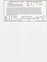
Below are the components of the Z886 trench drain typical
to an installation. Check your order to verify you have all
components particular to your job before beginning your
installation. Contact customer service at 855-ONE-ZURN
should additional material be required.
P887-INLET-6
Inlet Adapter (IA)
For Catch Basin Applications
Shipping and
Installation Bar
GL
Grate Lockdown
Hardware
P6-DGC
6" [152] Double Iron
Class C Grate
P886-E4-NS
4" [102]No-Hub
End Outlet
P886-E1-NS
Closed End Cap
P886-U4-NS
4" [102] No-Hub
Bottom Outlet
Grate Lockdown Bar
(840 Bag)
P886-JC-NS
Joint Connector
For Use When Creating High or Low Points

3
Z886 PERMA-TRENCH
INSTALLATION INSTRUCTIONS
Z886 Tools Required
Tape Measure
Phillips Head Screwdriver Hammer Utility Knife Marker
Cordless Drill
Reciprocating Saw Ear Protection Safety Glasses
Gloves
Hole Saw Caulk Gun

4
Z886 PERMA-TRENCH
INSTALLATION INSTRUCTIONS
Z886 Encasement
A 4" [102] new concrete encasement is minimum. Guidelines
for reinforcing an encasement would be to use the same
thick-ness and reinforcing used in the surrounding concrete
slab. Concrete must be vibrated to remove air voids in
encasement, especially under the frame rails.
Specifying engineer is responsible for concrete encasement
and reinforcing based upon application and local codes.
Excavation
Trench excavation must include the minimum of 4" [102] on
both sides and underneath or the slab thickness surrounding
the trench. Soft and/or shifting soil substrates may cause
cracking of the concrete and consequent movement of
the trench. It is critical that the concrete be poured on an
adequate foundation. Verify depth of trench excavation to
allow for the same thickness of concrete under and beside
the trench as the surrounding slab thickness.
4 [102]
MIN.
4 [102]
MIN.
6-1/4 [159]
1-1/4 [32]
4 [102]
INVERT

5
Z886 PERMA-TRENCH
INSTALLATION INSTRUCTIONS
Z886 Layout
Upon completion of the excavation, the channel should
be placed in numeric order alongside the excavation
according to the job layout. Each trench section has a
trench identification number and flow direction indicating
its sequence within the system. It is best to work from the
deep or outlet end to the shallow. Grates are not installed
at this time.
Four (4) shipping/installation bars per channel;
recommended spacing is approximately 3"-6" [76-152]
from end of rail for end pieces and 26"-29" [660-737] from
end of rail for center pieces. All shipping/installation bar
locations are approximate.
Female End
Must be installed on
channels without HD
or HDS frames

6
Z886 PERMA-TRENCH
INSTALLATION INSTRUCTIONS
Z886 End Outlet
Connection Options
1 When installing end cap or end outlet, remove
by cutting with saw the 1-1/4" [32] male overlap
connection as shown.
2 Once overlap is removed, trim end cap/end outlet
to desired height.
3 Attach end outlet or end cap to the channel with
hardware provided.
ATTACHING END CAPS AND OUTLETS
Make sure all overlaps on trench are trimmed o prior to
installing the end caps to ensure the finish installation has
a frame above the trench channel. This ensures each trench
will have a grate on it.
Scrap
Scra
p
Scrap

7
Z886 PERMA-TRENCH
INSTALLATION INSTRUCTIONS
Z886 Bottom Outlet Connection Option
1 Score both sides of the rib with the utility knife. 2 Tap rib with a hammer to remove rib when necessary.
4 Cut out hole with hole saw that matches inside diameter
of outlet.
3 Attach bottom outlet to channel with hardware provided.
Scrap
Scrap
Scrap

8
Z886 PERMA-TRENCH
INSTALLATION INSTRUCTIONS
Z886
Channel Connection
Z886 Neutral Cut
Channel Connection
1 When job layout calls for male-to-male channel
connection, cut male ends to be flush with end of integral
frame on the ends that will be connected.
1 Cut a 1-1/4" [32] by 13/16" [21] section out of the end of
the channel. This enables the end to act as a male end.
2 Screw the ribs together with the hardware provided.
This method can also be used if you have a female-to-
female connection.
2 After removing the cutouts, attach channel through
the female connection with hardware provided.
1.25" [32]
.813" [21]
Scrap
1.25" [32]
.813" [21]
Scrap
Scrap

9
Z886 PERMA-TRENCH
INSTALLATION INSTRUCTIONS
1 Cut joint connector to height. It should fit snug on the
radius portion of the trench to just below the upper lip of
the channel.
1 When job layout calls for female-to-female channel
connection with HD frame, cut female ends to be flush
with end of the HD frame on the ends that will be
connected.
2 Attach to the channels with the hardware provided. 2 Screw the joint connector to the channel with the
hardware provided. This method can also be used if you
have a male-to-male connection. Ends are not cut o, but
ribs will need to be trimmed (See page 7).
Z886 Connecting
the Trench
Z886-HD
Channel Connection
WITH JOINT CONNECTOR
Scrap
Scrap

10
Z886 PERMA-TRENCH
INSTALLATION INSTRUCTIONS
Z886 Connecting
the Trench
Channels should be installed from deep or outlet end
to shallow end. This allows the next shallower channel’s
male connection to easily set onto the previous channel
lip. Stake in place with No. 4 rebar (by others) and attach
with the provided connection hardware.
SEALING
• Channel connections are designed to be a good seal,
meaning concrete aggregate will not intrude into
the trench.
• Silicone sealant may be used as a gasket between the
channels for a better seal.
• Channel connections may be welded with an HDPE
welding gun for the best seal.
CONNECTIONS
• The maximum gap between frames is 1/4" [6].
Rebar length dictated by trench depth and substrate for positive
anchoring while setting to resist floating.
1 When using sidewalls with a joint connector, be sure to
keep the trimmed pieces to attach to the sidewall portion
of the trench using the hardware provided.
2 Attach to the channels with the hardware provided.
Z886 Connecting the
Trench with Sidewalls
Non-HD Frame
HD Frame

11
Z886 PERMA-TRENCH
INSTALLATION INSTRUCTIONS
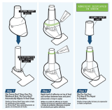
Z886 Catch Basins
CUT CHANNEL INSTALL
1 To make connection to a basin, invert the basin and
channel and trace the outline of the channel onto the
basin. This should be done for all sizes of basins.
2 Cutting the hole in the basin can be easily accomplished
with the use of a hand saw or power reciprocating saw.
Cut out the material inside of the traced area, including
the upper lip under the frame. Do not cut the frame.
4 Slide the male end of the channel into the inlet adapter,
attaching them together with the supplied hardware and
silicone caulk or construction adhesive.
3 After the channel outline is removed from the catch basin,
cut the inlet adapter to the height of the hole in the basin.
Secure the inlet adapter to the basin using the hardware
provided. Be sure to use silicone caulk or construction
adhesive to seal the adapter to the basin.
Scrap
Scrap

12
Z886 PERMA-TRENCH
INSTALLATION INSTRUCTIONS
Z886 Catch Basins
FULL CHANNEL INSTALL
1 To make connection to a basin, invert the basin and
channel and trace the outline of the channel onto the
basin. This should be done for all sizes of basins. Then
remove the mechanical joint.
2 Cutting the hole in the basin can be easily accomplished
with the use of a hand saw or power reciprocating saw.
Cut out the material inside of the traced area.
3 Slide the male end of the channel into the basin attaching
them together with the supplied hardware and silicone
caulk or construction adhesive through the ribbing.

13
Z886 PERMA-TRENCH
INSTALLATION INSTRUCTIONS
Z886 Catch Basins
FULL CHANNEL INSTALL WITH HEAVY-DUTY FRAME
1 To make connection to a basin, invert the basin and
channel and trace the outline of the channel onto the
basin. This should be done for all sizes of basins.
2 Cutting the hole in the basin can be easily accomplished
with the use of a hand saw or power reciprocating saw.
Cut out the material inside of the traced area.
4 Slide the male end of the channel into the inlet adapter
attaching them together with the supplied hardware and
silicone caulk or construction adhesive.
3 After the channel outline is removed from the catch
basin, cut the inlet adapter to just under the top of the
mechanical joint. Secure the inlet adapter to the basin
using the hardware provided. Be sure to use silicone caulk
or construction adhesive to seal the adapter to the basin.
Scrap
Scrap

14
Z886 PERMA-TRENCH
INSTALLATION INSTRUCTIONS
Z886
Setting the Trench
NEW CONSTRUCTION
Typically, a trench system is assembled from the outlet back.
Starting with the deepest section or catch basin, set the first
channel utilizing the integral rebar clip anchoring system.
Rebar clips are on both sides of each trench drain for easy
attachment to No. 4 rebar stakes. Slide the rebar into the
rebar clips. Then drive the stakes into the ground for positive
anchoring. Secure the trench to the rebar stakes with the
hardware provided with bag No. 841.
Adjust the trench to the desired elevation and repeat the
process with the next channel.
Set trench on rebar 1" [25] above final grade — this allows
final elevation adjustment with a hammer prior to pouring
concrete.
It is recommended to pour concrete the same day the trench
is set.
Recess trench 1/8" [3] below finish grade to ensure positive
flow into trench grate.

15
Z886 PERMA-TRENCH
INSTALLATION INSTRUCTIONS
A
1
8"
[3]shim or as required
1/8" shim
or as required
Z886
Setting the Trench
BLOCKOUT, RETROFIT, HANGING
An alternative means of installation is to suspend the trench
drain as shown. Wooden braces to hang the trench run can
be attached to the drain body through the grate lockdown
bars as illustrated below.

16
Z886 PERMA-TRENCH
INSTALLATION INSTRUCTIONS
Z886 Concrete
Pour and Finish
Pour the concrete around the three sides of the trench
drain. Be certain to adequately vibrate the concrete as
it is being placed. Proper vibration will eliminate any
unwanted voids within the concrete pour. If sidewalls
are used, a first and second pour are recommended.
Verify layout is correct prior to pouring concrete.
PLACING CONCRETE
• Adhere to check that the trench drain is in the
location required per the layout drawings prior to
pouring concrete.
• Standard concrete practices with expansion and
crack induction joints shall be followed based upon
local codes and standards.
• The trench drain shall not be used as an
expansion joint.
Finish troweling should be done to set the top edge of the
trench drain 1/8" [3] below the floor grade. Remember to
compensate for the concrete shrink that may occur during
cure so that the edge of the trench drain does not protrude
above the finished floor grade.
The use of nominal 1x6 (3/4" x 5-1/2") [20 x 140] lumber supplied by
others may be used to keep channel clear during the concrete pour.
Remove shipping/installation
bars as you finish troweling
5.5" [140]
.75" [19]

17
Z886 PERMA-TRENCH
INSTALLATION INSTRUCTIONS
Z886 Internal Sidewall
Extension Bracing
INSTALLATION WITH SIDEWALL EXTENSIONS
Use reinforcing every 10" [254] per bracing schedule
(bracing provided by others).
Standard 2 x 4’s
[51 x 102]
Height
Determined
By Invert
10" [254]
TYP
Height
Determined
by Invert
Standard 2 x 4’s
[51 x 102]

18
Z886 PERMA-TRENCH
INSTALLATION INSTRUCTIONS
Z886 Sidewall Concrete Pour
FULL CHANNEL INSTALL WITH HEAVY-DUTY FRAME
1 Set the channel to the correct height. 2 Install reinforcing per bracing schedule
(bracing provided by others).
4 Remove internal sidewall bracing.3 Using the standard concrete pouring method,
pour concrete so it is about 8" [204] from the top
of the trench.
5 Pour the remaining concrete, remove shipping/
installation bars, and use standard finishing practices
to finish the concrete.
POUR 1
POUR 2
6.25 [159]
4 [102]
MIN.
4 [102]
8 [203]

19
Z886 PERMA-TRENCH
INSTALLATION INSTRUCTIONS
Z886
Installing Grates
After the concrete has been poured, vibrated, and given
sucient time to dry, grate lockdown bolts must be
installed. The center of the grate should straddle the tie
strap that spans the frame. The exception is when both
channels and frames are cut. To place these grates, line
up the lockdown hole in the grate with the lockdown
hole in the tie strap. Lockdown bolts can be installed
using a 1/2" [13] socket.
LOCKING DOWN GRATES
• Start all lockdown bolts on each grate into the
lockdown prior to tightening them down.
• There may be gaps up to 1/4" [6] to ensure all grates
will lockdown.

Zurn Industries, LLC
1801 Pittsburgh Avenue
Erie, PA 16502, 855-663-9876
In Canada
Zurn Industries Limited
37900 Goreway Drive, Unit 10
Brampton, Ontario L6T 5W6, 905-405-8272
Form No. ZMKTG220-11, Rev. 11/16
-
 1
1
-
 2
2
-
 3
3
-
 4
4
-
 5
5
-
 6
6
-
 7
7
-
 8
8
-
 9
9
-
 10
10
-
 11
11
-
 12
12
-
 13
13
-
 14
14
-
 15
15
-
 16
16
-
 17
17
-
 18
18
-
 19
19
-
 20
20


Zurn Z886 Perma-Trench Installation Instructions Manual
- Type
- Installation Instructions Manual
Ask a question and I''ll find the answer in the document
Finding information in a document is now easier with AI
Related papers
-
Zurn P886-BAG-GL Installation guide
-
-
-
Wilkins 1-720AFT User manual
-
Zurn P415-3NL-CPT Installation guide
-
-
-
Zurn LC-FR05C4PRC Installation guide
-
Other documents
-
 Colmet 25VTCBK Operating instructions
-
Perma-Boot PB 312-1.5BR Operating instructions
-
 E-Z Connect 1981-RFLL Installation guide
-
Hubbell Internal Bracing Operating instructions
-
Everbilt 14987-23-3610 Operating instructions
-
 Perma-Boot PBR 312-2BK Operating instructions
-
Unbranded 1776-14-48 Operating instructions
-
 Abt PolyDrain Toggle Lock Installation guide
-
 Abt POLYDRAIN PDX-Pin Lock Installation guide
-
Sika 187783 User guide


