Supermicro SUPERSERVER 6038R-TXR User manual
- Category
- Server barebones
- Type
- User manual

SUPERSERVER
®
6038R-TXR
USER’S MANUAL
1.0a

Preface
About This Manual
This manual is written for professional system integrators and PC technicians. It
provides information for the installation and use of the SuperServer 6038R-TXR
server. Installation and maintenance should be performed by experienced
technicians only.
The SuperServer 6038R-TXR is based on the SC835XTQ-R982B 3U rackmount
server chassis and the Super X10DRX serverboard. Please refer to our web site
for an up-to-date list of supported operating systems, processors and memory.
Manual Organization
Chapter 1: Introduction
The rst chapter provides a checklist of the main components included with the
server system and describes the main features of the Super X10DRX serverboard
and the SC835XTQ-R982B chassis.
Chapter 2: Server Installation
This chapter describes the steps necessary to install the system into a rack and
check out the server conguration prior to powering up the system. If your server
was ordered without the processor and memory components, this chapter will refer
you to the appropriate sections of the manual for their installation.
Chapter 3: System Interface
Refer to this chapter for details on the system interface, which includes the functions
and information provided by the control panel on the chassis as well as other LEDs
located throughout the system.
Chapter 4: Standardized Warning Staements
You should thoroughly familiarize yourself with this chapter for a general overview
of safety precautions that should be followed when installing and servicing the
system.
Chapter 5: Advanced Serverboard Setup
Chapter 5 provides detailed information on the X10DRX serverboard, including the
locations and functions of connectors, headers and jumpers. Refer to this chapter
when adding or removing processors or main memory and when reconguring the
serverboard.
iii
Preface
The information in this User’s Manual has been carefully reviewed and is believed to be accurate.
The vendor assumes no responsibility for any inaccuracies that may be contained in this document,
makes no commitment to update or to keep current the information in this manual, or to notify any
person or organization of the updates. Please Note: For the most up-to-date version of this
manual, please see our web site at www.supermicro.com.
Super Micro Computer, Inc. ("Supermicro") reserves the right to make changes to the product
described in this manual at any time and without notice. This product, including software and
documentation, is the property of Supermicro and/or its licensors, and is supplied only under a
license. Any use or reproduction of this product is not allowed, except as expressly permitted by
the terms of said license.
IN NO EVENT WILL SUPERMICRO BE LIABLE FOR DIRECT, INDIRECT, SPECIAL, INCIDENTAL,
SPECULATIVE OR CONSEQUENTIAL DAMAGES ARISING FROM THE USE OR INABILITY TO
USE THIS PRODUCT OR DOCUMENTATION, EVEN IF ADVISED OF THE POSSIBILITY OF
SUCH DAMAGES. IN PARTICULAR, SUPERMICRO SHALL NOT HAVE LIABILITY FOR ANY
HARDWARE, SOFTWARE, OR DATA STORED OR USED WITH THE PRODUCT, INCLUDING THE
COSTS OF REPAIRING, REPLACING, INTEGRATING, INSTALLING OR RECOVERING SUCH
HARDWARE, SOFTWARE, OR DATA.
Any disputes arising between manufacturer and customer shall be governed by the laws of Santa
Clara County in the State of California, USA. The State of California, County of Santa Clara shall
be the exclusive venue for the resolution of any such disputes. Super Micro's total liability for all
claims will not exceed the price paid for the hardware product.
FCC Statement: This equipment has been tested and found to comply with the limits for a Class
A digital device pursuant to Part 15 of the FCC Rules. These limits are designed to provide
reasonable protection against harmful interference when the equipment is operated in a commercial
environment. This equipment generates, uses, and can radiate radio frequency energy and, if not
installed and used in accordance with the manufacturer’s instruction manual, may cause harmful
interference with radio communications. Operation of this equipment in a residential area is likely
to cause harmful interference, in which case you will be required to correct the interference at your
own expense.
California Best Management Practices Regulations for Perchlorate Materials: This Perchlorate
warning applies only to products containing CR (Manganese Dioxide) Lithium coin cells. “Perchlorate
Material-special handling may apply. See www.dtsc.ca.gov/hazardouswaste/perchlorate”
WARNING: Handling of lead solder materials used in this
product may expose you to lead, a chemical known to
the State of California to cause birth defects and other
reproductive harm.
Manual Revision 1.0a
Release Date: April 15, 2016
Unless you request and receive written permission from Super Micro Computer, Inc., you may not
copy any part of this document.
Information in this document is subject to change without notice. Other products and companies
referred to herein are trademarks or registered trademarks of their respective companies or mark
holders.
Copyright © 2016 by Super Micro Computer, Inc.
All rights reserved.
Printed in the United States of America

v
SUPERSERVER 6038R-TXR User's Manual
Preface
iv
Notes
Chapter 6: Advanced Chassis Setup
Refer to Chapter 6 for detailed information on the SC835XTQ-R982B server chassis.
You should follow the procedures given in this chapter when installing, removing or
reconguring SATA or peripheral drives and when replacing system power supply
units and cooling fans.
Chapter 7: BIOS
The BIOS chapter includes an introduction to BIOS and provides detailed information
on running the CMOS Setup Utility.
Appendix A: BIOS POST Messages
Appendix B: System Specications

vii
Table of Contents
vi
Table of Contents
Chapter 1 Introduction
1-1 Overview ......................................................................................................... 1-1
1-2 Serverboard Features ..................................................................................... 1-2
Processors ...................................................................................................... 1-2
Memory ........................................................................................................... 1-2
Serial ATA ....................................................................................................... 1-2
PCI Expansion Slots ....................................................................................... 1-2
Rear I/O Ports ................................................................................................. 1-2
IPMI ................................................................................................................. 1-2
System Power ................................................................................................. 1-3
SATA Subsystem ............................................................................................. 1-3
Front Control Panel ......................................................................................... 1-3
Cooling System ............................................................................................... 1-3
1-4 Contacting Supermicro .................................................................................... 1-5
Chapter 2 Server Installation
2-1 Overview ......................................................................................................... 2-1
2-2 Unpacking the System .................................................................................... 2-1
2-3 Preparing for Setup ......................................................................................... 2-1
Choosing a Setup Location ............................................................................. 2-1
2-4 Warnings and Precautions .............................................................................. 2-2
Rack Precautions ............................................................................................ 2-2
Server Precautions .......................................................................................... 2-2
Rack Mounting Considerations ....................................................................... 2-3
Ambient Operating Temperature ................................................................ 2-3
Reduced Airow ......................................................................................... 2-3
Mechanical Loading ................................................................................... 2-3
Circuit Overloading ..................................................................................... 2-3
Reliable Ground ......................................................................................... 2-3
2-5 Installing the System into a Rack ................................................................... 2-4
Installing the Inner Rack Rails ........................................................................ 2-4
Installing the Outer Rack Rails ....................................................................... 2-5
Installing the Chassis into a Rack................................................................... 2-6
Chapter 3 System Interface
3-1 Overview ......................................................................................................... 3-1
3-2 Control Panel Buttons ..................................................................................... 3-1
Reset ............................................................................................................... 3-1
Power .............................................................................................................. 3-1
3-3 Control Panel LEDs ........................................................................................ 3-2
Power Fail ....................................................................................................... 3-2
Information LED .............................................................................................. 3-2
NIC1 ................................................................................................................ 3-2
NIC2 ................................................................................................................ 3-2
HDD ................................................................................................................. 3-3
Power .............................................................................................................. 3-3
3-4 Drive Carrier LEDs .......................................................................................... 3-3
Chapter 4 Standardized Warning Statements for AC Systems
4-1 About Standardized Warning Statements ....................................................... 4-1
Warning Denition ........................................................................................... 4-1
Installation Instructions .................................................................................... 4-4
Circuit Breaker ................................................................................................ 4-5
Power Disconnection Warning ........................................................................ 4-6
Equipment Installation ..................................................................................... 4-8
Restricted Area ................................................................................................ 4-9
Battery Handling ............................................................................................ 4-10
Redundant Power Supplies .......................................................................... 4-12
Backplane Voltage ........................................................................................ 4-13
Comply with Local and National Electrical Codes ........................................ 4-14
Product Disposal ........................................................................................... 4-15
Hot Swap Fan Warning ................................................................................. 4-16
Power Cable and AC Adapter ...................................................................... 4-18
Chapter 5 Advanced Serverboard Setup
5-1 Handling the Serverboard ............................................................................... 5-1
Precautions ..................................................................................................... 5-1
5-2 Connecting Cables .......................................................................................... 5-2
Connecting Data Cables ................................................................................. 5-2
Connecting Power Cables .............................................................................. 5-2
Connecting the Control Panel ......................................................................... 5-2
5-3 I/O Ports .......................................................................................................... 5-3
5-4 Installing the Processor and Heatsink ............................................................ 5-4
Installing an LGA 2011 Processor ................................................................... 5-4
Installing a CPU Heatsink ............................................................................... 5-7
Removing the Heatsink ................................................................................... 5-8
5-6 Installing Memory ............................................................................................ 5-9
Memory Support ....................................................................................... 5-10
5-6 Adding PCI Add-On Cards .............................................................................5-11
5-7 Serverboard Details ...................................................................................... 5-13
SUPERSERVER 6038R-TXR User's Manual

viii
X10DRX Quick Reference ............................................................................ 5-13
5-8 Connector Denitions ................................................................................... 5-15
5-9 Jumper Settings ............................................................................................ 5-21
5-10 Onboard Indicators ........................................................................................ 5-23
5-11 SATA Ports .................................................................................................... 5-24
5-12 Installing Software ......................................................................................... 5-25
SuperDoctor® 5 ............................................................................................ 5-26
5-13 Onboard Battery ............................................................................................ 5-27
Chapter 6 Advanced Chassis Setup
6-1 Static-Sensitive Devices .................................................................................. 6-1
Precautions ..................................................................................................... 6-1
6-2 Control Panel .................................................................................................. 6-2
6-3 Accessing the Inside of the System................................................................ 6-3
6-3 System Fans ................................................................................................... 6-4
System Fan Failure ......................................................................................... 6-4
Replacing System Fans .................................................................................. 6-4
Installing the Rear Fan .................................................................................... 6-4
Air Shroud ....................................................................................................... 6-6
6-4 Drive Bay Installation/Removal ....................................................................... 6-6
Accessing the Drive Bays ............................................................................... 6-6
Hard Drive Backplane ..................................................................................... 6-6
SATA Drive Installation .................................................................................... 6-6
DVD-ROM Drive Installation ........................................................................... 6-9
6-5 Power Supply ................................................................................................ 6-10
Power Supply Failure .................................................................................... 6-10
Replacing the Power Supply ......................................................................... 6-10
Chapter 7 BIOS
7-1 Introduction ...................................................................................................... 7-1
7-2 Main Setup ...................................................................................................... 7-2
7-3 Advanced Setup Congurations...................................................................... 7-3
7-4 Event Logs .................................................................................................... 7-31
4-5 IPMI ............................................................................................................... 7-33
7-6 Security Settings ........................................................................................... 7-36
7-7 Boot Settings ................................................................................................. 7-39
7-8 Save & Exit ................................................................................................... 7-41
Appendix A BIOS Error Beep Codes
Appendix B System Specications
SUPERSERVER 6038R-TXR User's Manual

Chapter 1
Introduction
1-1 Overview
The SuperServer 6038R-TXR is comprised of two main subsystems: the
SC835XTQ-R982B 3U server chassis and the X10DRX dual Intel Xeon processor
serverboard. Please refer to our website for information on operating systems that
have been certied for use with the system (www.supermicro.com).
In addition to the serverboard and chassis, various hardware components have
been included with the server, as listed below:
• One 8-cm rear exhaust fan (FAN-0125L4)
• Three 8-cm system fans (FAN-0118L4)
• One air shroud (MCP-310-83501-0N)
• Two 2U passive CPU heatsinks (SNK-P0048PS)
• SATA accessories:
One HDD backplane (BPN-SAS-833TQ)
Eight 3.5" hard disk drive trays (MCP-220-00075-0B)
Two 5.25" drive trays (MCP-220-00009-01)
• One rack rail kit (MCP-290-00053-0N)
Note: For your system to work properly, please follow the links below to download
all necessary drivers/utilities and the user’s manual for your server.
• Supermicro product manuals: http://www.supermicro.com/support/manuals/
• Product drivers and utilities: ftp://ftp.supermicro.com
• Product safety info: http://www.supermicro.com/about/policies/safety_informa-
tion.cfm
Chapter 1: Introduction
1-1

1-2 1-3
Chapter 1: Introduction
SUPERSERVER 6038R-TXR User's Manual
1-2 Serverboard Features
At the heart of the SuperServer 6038R-TXR lies the X10DRX, a dual processor
serverboard based on the Intel C612 chipset. Below are the main features of the
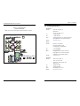
X10DRX. (See Figure 1-1 for a block diagram of the chipset.)
Processors
The X10DRX supports two Intel
®
E5-2600 v3/v4 Series processors in LGA 2011
sockets (Socket R3). Please refer to the serverboard description pages on our
website for a complete listing of supported processors (www.supermicro.com).
Memory
The X10DRX has sixteen DIMM slots that can support up to 2 TB of ECC
LRDIMM (Load Reduced DIMM) or 512 GB of ECC RDIMM (Registered DIMM)
DDR4-2400/2133/1866/1600 memory. Modules of the same size and speed are
recommended. See Chapter 5 for details.
Serial ATA
A SATA controller is integrated into the chipset to provide a ten-port SATA 3.0
subsystem, which is RAID 0, 1, 5 and 10 supported. The I-SATA0 through I-SATA5
ports are supported by the Intel PCH while the S-SATA0 through S-SATA0-3 ports
are supported by the Intel SCU. The SATA drives are hot-swappable units.
Note: The operating system you use must have RAID support to enable the hot-
swap capability and RAID function of the Serial ATA drives.
PCI Expansion Slots
The X10DRX has ten PCI-E 3.0 x8 and one PCI-E 2.0 x4 (in x8) slots for a total
of eleven PCI expansion slots.
Rear I/O Ports
The rear I/O ports include one COM port, a VGA (monitor) port, four USB 2.0 ports,
a dedicated IPMI LAN port and two Gb Ethernet LAN ports.
IPMI
IPMI (Intelligent Platform Management Interface) is a hardware-level interface
specication that provides remote access, monitoring and administration for
Supermicro server platforms. IPMI allows server administrators to view a server’s
hardware status remotely, receive an alarm automatically if a failure occurs, and
power cycle a system that is non-responsive.
1-3 Server Chassis Features
The following is a general outline of the main features of the SC835XTQ-R982B
server chassis.
System Power
The SC835XTQ-R982B features a redundant 980W high-efciency power supply
composed of two separate power modules. This power redundancy feature allows
you to replace a failed power supply without shutting down the system.
SATA Subsystem
The SC835XTQ-R982B supports up to eight SATA drives. These drives are hot-
swappable units and are connected to a backplane that provides power and control.
Front Control Panel
The control panel on the SuperServer 6038R-TXR provides you with system
monitoring and control. LEDs indicate system power, HDD activity, network activity,
system overheat and power supply failure. The main power button and a system
reset button are also located here.
Cooling System
The SC835XTQ-R982B chassis has an innovative cooling design that includes three
8-cm hot-plug system cooling fans located in the middle section of the chassis and
one 8-cm exhaust fan. An air shroud channels the airow from the system fans to
efciently cool the processor area of the system. The power supply module also
includes a cooling fan.

1-4 1-5
Chapter 1: Introduction
SUPERSERVER 6038R-TXR User's Manual
1-4 Contacting Supermicro
Headquarters
Address: Super Micro Computer, Inc.
980 Rock Ave.
San Jose, CA 95131 U.S.A.
Tel: +1 (408) 503-8000
Fax: +1 (408) 503-8008
Email: [email protected] (General Information)
[email protected] (Technical Support)
Website: www.supermicro.com
Europe
Address: Super Micro Computer B.V.
Het Sterrenbeeld 28, 5215 ML
's-Hertogenbosch, The Netherlands
Tel: +31 (0) 73-6400390
Fax: +31 (0) 73-6416525
Email: [email protected] (General Information)
[email protected] (Technical Support)
[email protected] (Customer Support)
Website: www.supermicro.nl
Asia-Pacic
Address: Super Micro Computer, Inc.
3F, No. 150, Jian 1st Rd.
Zhonghe Dist., New Taipei City 235
Taiwan (R.O.C)
Tel: +886-(2) 8226-3990
Fax: +886-(2) 8226-3992
Email: [email protected]
Website: www.supermicro.com.tw
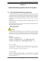
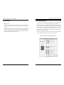
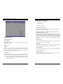
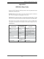
Figure 1-1. Intel C612 Chipset:
System Block Diagram
Note: This is a general block diagram. Please see Chapter 5 for details.
6 PHASE
145W
VR12.5
VCCP0&1 12v
P1
P1
P0
P0
DMIPE1PE2PE3
PE3 PE1PE2
port 4,5(USB2.0)
REAR
#1
#2
A
G
PROCESSOR 1
PROCESSOR 2
#2
#1
DDR4 DIMM
REAR
B
C
D
E
F H
#1
#2
#1
#2
#1
#2 #2
#1
#1
#2
#1
#2
port 1,2(USB3.0)
+
port 0,1(USB2.0)
port 3,4(USB3.0)
+
port 2,3(USB2.0)
port 8,9(USB2.0)
TYPE A
port 5(USB3.0)
+
port 10(USB2.0)
PCIE-3.0 x8 * 5
PCIE-2.0 x4 * 1
x8 * 5
PCIE3.0 x8 Slots [6/7/8/9/10]
PCIE2.0 x8 Slots 11(x4)
CPU REAR
CPU FRONT
QPI
DDR4 DIMM
DDR4 DIMM
DDR4 DIMM
DDR4 DIMM
DDR4 DIMM
DDR4 DIMM
DDR4 DIMM
QPI
9.6GT/s
PCIE3.0 x8 Slots [1/2/3/4/5]
4GB/s
x4
UL1
Dual LAN
I350AM2
JLAN1
RJ45
JLAN2
RJ45
To BMC RMII port
NC-SI
S-SATA0
S-SATA1
S-SATA2
S-SATA3
I-SATA0
I-SATA1
I-SATA2
I-SATA3
I-SATA4
I-SATA5
sSATA Gen3 [0..3]
PET [5,6,7,8]
SATA Gen3 [0..5]
DMI
PCH
PET4
SPI
USB2.0 [0..5]
USB3.0 [1..6]
LPC
USB2.0 [6,7]
NC-SI(RMII)
UL1
BMC
AST2400
HWM
SPI FLASH
16MB BIOS
16MB BMC
SPI FLASH
DDR3
VGA
TPM Header
IPMI LAN
RJ45
PHY
RTL8211E
COM1
HDR 2x5
HDR 2x10
DMI
X10DRX Block Diagram Rev. 1.00

1-6
SUPERSERVER 6038R-TXR User's Manual
Notes

Chapter 2: Server Installation
2-1
Chapter 2
Server Installation
2-1 Overview
This chapter provides a quick setup checklist to install the 6038R-TXR into a rack.
If your system is not already fully integrated with a serverboard, processors, system
memory etc., please turn to the chapter or section noted in each step for details on
installing specic components.
2-2 Unpacking the System
You should inspect the box the SuperServer 6038R-TXR was shipped in and note
if it was damaged in any way. If the server itself shows damage you should le a
damage claim with the carrier who delivered it.
Decide on a suitable location for the rack unit that will hold the SuperServer 6038R-
TXR. It should be situated in a clean, dust-free area that is well ventilated. Avoid
areas where heat, electrical noise and electromagnetic elds are generated. You
will also need it placed near a grounded power outlet. Read the Rack and Server
Precautions in the next section.
2-3 Preparing for Setup
The box the SuperServer 6038R-TXR was shipped in should include two sets of rail
assemblies, two rail mounting brackets and the mounting screws you will need to
install the system into the rack. Follow the steps in the order given to complete the
installation process in a minimum amount of time. Please read this section in its en-
tirety before you begin the installation procedure outlined in the sections that follow.
Choosing a Setup Location
• Leave enough clearance in front of the rack to enable you to open the front door
completely (~25 inches) and approximately 30 inches of clearance in the back
of the rack to allow for sufcient airow and ease in servicing.
• This product is for installation only in a Restricted Access Location (dedicated
equipment rooms, service closets and the like).

Chapter 2: Server Installation
2-32-2
SUPERSERVER 6038R-TXR User's Manual
• This product is not suitable for use with visual display work place devices
acccording to §2 of the the German Ordinance for Work with Visual Display
Units.
2-4 Warnings and Precautions
Rack Precautions
• Ensure that the leveling jacks on the bottom of the rack are fully extended to
the oor with the full weight of the rack resting on them.
• In single rack installation, stabilizers should be attached to the rack. In multiple
rack installations, the racks should be coupled together.
• Always make sure the rack is stable before extending a component from the
rack.
• You should extend only one component at a time - extending two or more si-
multaneously may cause the rack to become unstable.
Server Precautions
• Review the electrical and general safety precautions in Chapter 4.
• Determine the placement of each component in the rack before you install the
rails.
• Install the heaviest server components on the bottom of the rack rst, and then
work up.
• Use a regulating uninterruptible power supply (UPS) to protect the server from
power surges, voltage spikes and to keep your system operating in case of a
power failure.
• Allow any hot plug drives and power supply modules to cool before touching
them.
• Always keep the rack's front door and all panels and components on the servers
closed when not servicing to maintain proper cooling.
Warning! To prevent bodily injury when mounting or servicing this unit in a
rack, you must take special precautions to ensure that the system remains
stable. The following guidelines are provided to ensure your safety:
• This unit should be mounted at the bottom of the rack if it is the only unit in
the rack.
• When mounting this unit in a partially lled rack, load the rack from the bottom
to the top with the heaviest component at the bottom of the rack.
• If the rack is provided with stabilizing devices, install the stabilizers before
mounting or servicing the unit in the rack.
Rack Mounting Considerations
Ambient Operating Temperature
If installed in a closed or multi-unit rack assembly, the ambient operating tempera-
ture of the rack environment may be greater than the ambient temperature of the
room. Therefore, consideration should be given to installing the equipment in an
environment compatible with the manufacturer’s maximum rated ambient tempera-
ture (Tmra).
Reduced Airow
Equipment should be mounted into a rack so that the amount of airow required
for safe operation is not compromised.
Mechanical Loading
Equipment should be mounted into a rack so that a hazardous condition does not
arise due to uneven mechanical loading.
Circuit Overloading
Consideration should be given to the connection of the equipment to the power
supply circuitry and the effect that any possible overloading of circuits might have
on overcurrent protection and power supply wiring. Appropriate consideration of
equipment nameplate ratings should be used when addressing this concern.
Reliable Ground
A reliable ground must be maintained at all times. To ensure this, the rack itself
should be grounded. Particular attention should be given to power supply connec-
tions other than the direct connections to the branch circuit (i.e. the use of power
strips, etc.).

Chapter 2: Server Installation
2-52-4
SUPERSERVER 6038R-TXR User's Manual
2-5 Installing the System into a Rack
This section provides information on installing the SC835 chassis into a rack unit
with the quick-release rails provided. There are a variety of rack units on the market,
which may mean the assembly procedure will differ slightly. You should also refer to
the installation instructions that came with the rack unit you are using.
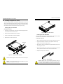
Installing the Inner Rack Rails
Installing the Inner Rails
1. Place the inner rack extensions on the side of the chassis aligning the hooks
of the chassis with the rail extension holes.
2. Slide the extension toward the front of the chassis.
3. Secure the chassis with four screws as illustrated.
4. Repeat steps 1-3 for the other inner rail.
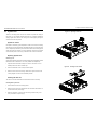
Figure 2-1. Installing the Inner Rack Rails
Screw Holes
1
1
1
2
Figure 2-3. Outer Rack Rails
Installing the Outer Rack Rails
Outer rails attach to the server rack and hold the server in place. The outer rails for
the SC835 chassis extend between 30 inches and 33 inches.
Installing the Outer Rails
1. Begin by measuring the distance from the front rail to the rear rail of the rack
2. Attach a short bracket to the front side of the right outer rail and a long
bracket to the rear side of the right outer rail.
3. Adjust both the short and long brackets to the proper distance so that the rail
can t snugly into the rack.
4. Secure the short bracket to the front side of the outer rail with two screws and
the long bracket to the rear side of the outer rail with three screws.
5. Repeat these steps for the left outer rail.
Figure 2-2. Inner Rack Rails Installed
Warning: do not pick up the server with the front handles. They are de-
signed to pull the system from a rack only.
Slide rail mounted equipment is not to be used as a shelf or a work space.
Warning: Stability hazard. The rack stabilizing mechanism must be in
place, or the rack must be bolted to the oor before you slide the unit out
for servicing. Failure to stabilize the rack can cause the rack to tip over.

2-6
SUPERSERVER 6038R-TXR User's Manual
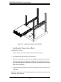
Figure 2-4. Installing the Chassis into the Rack
Installing the Chassis into a Rack
Installing into a Rack
1. Conrm that the inner and outer rails are installed on the rack.
2. Line chassis rails with the front of the rack rails.
3. Slide the chassis rails into the rack rails, keeping the pressure even on both
sides (you may have to depress the locking tabs when inserting). When the
server has been pushed completely into the rack, you should hear the locking
tabs "click" into position.
4. (Optional) Insert and tighten the thumbscrews that hold the front of the server
to the rack.
Note: The gure above is for illustrative purposes only. Always install servers to
the bottom of the rack rst.

Chapter 3: System Interface
3-1
Chapter 3
System Interface
3-1 Overview
There are several LEDs on the control panel as well as others on the drive carri-
ers to keep you constantly informed of the overall status of the system as well as
the activity and health of specic components. There are also two buttons on the
chassis control panel.
3-2 Control Panel Buttons
The two buttons located on the front of the chassis include a reset button and a
power on/off button.
Reset
Use the reset button to reboot the system.
Power
This is the main power button, which is used to apply or turn off the main system
power. Turning off system power with this button removes the main power but keeps
standby power supplied to the system.

SUPERSERVER 6038R-TXR User's Manual Chapter 3: System Interface
3-2 3-3
1
2
3-3 Control Panel LEDs
The control panel located on the front of the chassis has several LEDs. These
LEDs provide you with critical information related to different parts of the system.
This section explains what each LED indicates when illuminated and any corrective
action you may need to take.
Power Fail
Indicates a power supply module has failed. The second power supply module will
take the load and keep the system running but the failed module will need to be
replaced. Refer to Chapter 6 for details on replacing the power supply. This LED
should be off when the system is operating normally.
NIC1
Indicates network activity on the LAN1 port when ashing.
NIC2
Indicates network activity on the LAN2 port when ashing.
HDD
On the SuperServer 6038R-TXR, this LED indicates SATA hard drive and/or DVD-
ROM drive activity when ashing.
Power
Indicates power is being supplied to the system's power supply units. This LED
should normally be illuminated when the system is operating.
3-4 Drive Carrier LEDs
Each drive carrier has two LEDs:
• Green: When illuminated, the green LED on the drive carrier indicates drive
activity. A connection to the backplane enables this LED to blink on and off
when that particular drive is being accessed.
• Red: The red LED to indicate a drive failure. If one of the drives fails, you should
be notied by your system management software. Please refer to Chapter 6 for
instructions on replacing failed drives.
Information LED
This LED will be solid blue when the UID function has been activated. When this
LED ashes red, it indicates a fan failure. When red continuously it indicates an
overheat condition, which may be caused by cables obstructing the airow in the
system or the ambient room temperature being too warm. Check the routing of
the cables and make sure all fans are present and operating normally. You should
also check to make sure that the chassis covers are installed. Finally, verify that
the heatsinks are installed properly (see Chapter 5). This LED will remain ashing
or on as long as the indicated condition exists.

SUPERSERVER 6038R-TXR User's Manual
3-4
Notes

4-1
Chapter 4: Warning Statements for AC Systems
Chapter 4
Standardized Warning Statements for AC Systems
4-1 About Standardized Warning Statements
The following statements are industry standard warnings, provided to warn the user
of situations which have the potential for bodily injury. Should you have questions
or experience difficulty, contact Supermicro's Technical Support department
for assistance. Only certied technicians should attempt to install or congure
components.
Read this appendix in its entirety before installing or conguring components in the
Supermicro chassis.
These warnings may also be found on our web site at http://www.supermicro.com/
about/policies/safety_information.cfm.
Warning Denition
Warning!
This warning symbol means danger. You are in a situation that could cause bodily
injury. Before you work on any equipment, be aware of the hazards involved with
electrical circuitry and be familiar with standard practices for preventing accidents.
警告の定義
この警告サインは危険を意味します。
人身事故につながる可能性がありますので、いずれの機器でも動作させる前に、
電気回路に含まれる危険性に注意して、標準的な事故防止策に精通して下さい。
此警告符号代表危险。
您正处于可能受到严重伤害的工作环境中。在您使用设备开始工作之前,必须充分
意识到触电的危险,并熟练掌握防止事故发生的标准工作程序。请根据每项警告结
尾的声明号码找到此设备的安全性警告说明的翻译文本。
此警告符號代表危險。
您正處於可能身體可能會受損傷的工作環境中。在您使用任何設備之前,請注意觸
電的危險,並且要熟悉預防事故發生的標準工作程序。請依照每一注意事項後的號
碼找到相關的翻譯說明內容。

4-2
SUPERSERVER 6038R-TXR User's Manual
4-3
Warning Statements for AC Systems
Warnung
WICHTIGE SICHERHEITSHINWEISE
Dieses Warnsymbol bedeutet Gefahr. Sie benden sich in einer Situation, die zu
Verletzungen führen kann. Machen Sie sich vor der Arbeit mit Geräten mit den
Gefahren elektrischer Schaltungen und den üblichen Verfahren zur Vorbeugung
vor Unfällen vertraut. Suchen Sie mit der am Ende jeder Warnung angegebenen
Anweisungsnummer nach der jeweiligen Übersetzung in den übersetzten
Sicherheitshinweisen, die zusammen mit diesem Gerät ausgeliefert wurden.
BEWAHREN SIE DIESE HINWEISE GUT AUF.
INSTRUCCIONES IMPORTANTES DE SEGURIDAD
Este símbolo de aviso indica peligro. Existe riesgo para su integridad física. Antes
de manipular cualquier equipo, considere los riesgos de la corriente eléctrica y
familiarícese con los procedimientos estándar de prevención de accidentes. Al
nal de cada advertencia encontrará el número que le ayudará a encontrar el texto
traducido en el apartado de traducciones que acompaña a este dispositivo.
GUARDE ESTAS INSTRUCCIONES.
IMPORTANTES INFORMATIONS DE SÉCURITÉ
Ce symbole d'avertissement indique un danger. Vous vous trouvez dans une
situation pouvant entraîner des blessures ou des dommages corporels. Avant
de travailler sur un équipement, soyez conscient des dangers liés aux circuits
électriques et familiarisez-vous avec les procédures couramment utilisées pour
éviter les accidents. Pour prendre connaissance des traductions des avertissements
gurant dans les consignes de sécurité traduites qui accompagnent cet appareil,
référez-vous au numéro de l'instruction situé à la n de chaque avertissement.
CONSERVEZ CES INFORMATIONS.
안전을 위한 주의사항
경고!
이 경고 기호는 위험이 있음을 알려 줍니다. 작업자의 신체에 부상을 야기 할 수
있는 상태에 있게 됩니다. 모든 장비에 대한 작업을 수행하기 전에 전기회로와
관련된 위험요소들을 확인하시고 사전에 사고를 방지할 수 있도록 표준 작업절차를
준수해 주시기 바랍니다.
해당 번역문을 찾기 위해 각 경고의 마지막 부분에 제공된 경고문 번호를
참조하십시오
BELANGRIJKE VEILIGHEIDSINSTRUCTIES
Dit waarschuwings symbool betekent gevaar. U verkeert in een situatie die
lichamelijk letsel kan veroorzaken. Voordat u aan enige apparatuur gaat werken,
dient u zich bewust te zijn van de bij een elektrische installatie betrokken risico's
en dient u op de hoogte te zijn van de standaard procedures om ongelukken te
voorkomen. Gebruik de nummers aan het eind van elke waarschuwing om deze te
herleiden naar de desbetreffende locatie.
BEWAAR DEZE INSTRUCTIES
. !
ן
ונקת תורהצהאהרהז
ןה תואבה תורהצהא ינפמ שמתשמה תא ריהזהל תנמ לע ,היישעתה ינקת יפ לע תורהז הלבח
ה וא תולאש שיו הדימב .תירשפא תיזיפי ,יהשלכ היעבב תולקתרוציל שי הכימת תקלחמ םע רשק
רידגהל וא ןיקתהל םיאשר דבלב םיכמסומ םיאנכט .ורקימרפוס לש תינכט תאה .םיביכר
אורקל שי .ורקימרפוס יזראמב םיביכרה תרדגה וא תנקתה ינפל ואולמב חפסנה תא

4-4 4-5
Chapter 4: Warning Statements for AC SystemsSUPERSERVER 6038R-TXR User's Manual
Installation Instructions
Warning!
Read the installation instructions before connecting the system to the power source.
設置手順書
システムを電源に接続する前に、設置手順書をお読み下さい。
警告
将此系统连接电源前,请先阅读安装说明。
警告
將系統與電源連接前,請先閱讀安裝說明。
Warnung
Vor dem Anschließen des Systems an die Stromquelle die Installationsanweisungen
lesen.
¡Advertencia!
Lea las instrucciones de instalación antes de conectar el sistema a la red de
alimentación.
Attention
Avant de brancher le système sur la source d'alimentation, consulter les directives
d'installation.
Circuit Breaker
Warning!
This product relies on the building's installation for short-circuit (overcurrent)
protection. Ensure that the protective device is rated not greater than: 250 V, 20 A.
サーキット・ブレーカー
この製品は、短絡(過電流)保護装置がある建物での設置を前提としています。
保護装置の定格が250 V、20 Aを超えないことを確認下さい。
警告
此产品的短路(过载电流)保护由建筑物的供电系统提供,确保短路保护设备的额定电
流不大于250V,20A。
警告
此產品的短路(過載電流)保護由建築物的供電系統提供,確保短路保護設備的額定電
流不大於250V,20A。
Warnung
Dieses Produkt ist darauf angewiesen, dass im Gebäude ein Kurzschluss-
bzw. Überstromschutz installiert ist. Stellen Sie sicher, dass der Nennwert der
Schutzvorrichtung nicht mehr als: 250 V, 20 A beträgt.
¡Advertencia!
Este equipo utiliza el sistema de protección contra cortocircuitos (o sobrecorrientes)
del edicio. Asegúrese de que el dispositivo de protección no sea superior a: 250
V, 20 A.
Attention
Pour ce qui est de la protection contre les courts-circuits (surtension), ce produit
dépend de l'installation électrique du local. Vériez que le courant nominal du
dispositif de protection n'est pas supérieur à :250 V, 20 A.
אורקל שי רוקמל תכרעמה רוביח ינפל הנקתה תוארוה תאחתמ.
시스템을 전원에 연결하기 전에 설치 안내를 읽어주십시오.
Waarschuwing
Raadpleeg de installatie-instructies voordat u het systeem op de voedingsbron
aansluit.
לע ךמתסמ הז רצומנגהה תעינמל םינבמב תנקתומה יכ אדוול שי .ילמשח רצק
רצקה ינפמ ןגמה רישכמה ילמשחהמ רתוי אל אוה-250 V, 20 A

4-6 4-7
Chapter 4: Warning Statements for AC SystemsSUPERSERVER 6038R-TXR User's Manual
Power Disconnection Warning
Warning!
The system must be disconnected from all sources of power and the power cord
removed from the power supply module(s) before accessing the chassis interior to
install or remove system components.
電源切断の警告
システムコンポーネントの取り付けまたは取り外しのために、シャーシー内部にアクセス
するには、
システムの電源はすべてのソースから切断され、電源コードは電源モジュールから取り
外す必要があります。
警告
在你打开机箱并安装或移除内部器件前,必须将系统完全断电,并移除电源线。
警告
在您打開機殼安裝或移除內部元件前,必須將系統完全斷電,並移除電源線。
경고!
이 제품은 전원의 단락(과전류)방지에 대해서 전적으로 건물의 관련 설비에
의존합니다. 보호장치의 정격이 반드시 250V(볼트), 20A(암페어)를 초과하지
않도록 해야 합니다.
Waarschuwing
Dit product is afhankelijk van de kortsluitbeveiliging (overspanning) van uw electrische
installatie. Controleer of het beveiligde aparaat niet groter gedimensioneerd is dan
220V, 20A.
Warnung
Das System muss von allen Quellen der Energie und vom Netzanschlusskabel
getrennt sein, das von den Spg.Versorgungsteilmodulen entfernt wird, bevor es
auf den Chassisinnenraum zurückgreift, um Systemsbestandteile anzubringen oder
zu entfernen.
¡Advertencia!
El sistema debe ser disconnected de todas las fuentes de energía y del cable
eléctrico quitado de los módulos de fuente de alimentación antes de tener acceso
el interior del chasis para instalar o para quitar componentes de sistema.
Attention
Le système doit être débranché de toutes les sources de puissance ainsi que de
son cordon d'alimentation secteur avant d'accéder à l'intérieur du chassis pour
installer ou enlever des composants de systéme.
ילמשח קותינ ינפמ הרהזא
!הרהזא
למשחה תורוקמ לכמ תכרעמה תא קתנל שי ריסהל שיו קפסהמ ילמשחה לבכ תא
נקתה ךרוצל זראמה לש ימינפה קלחל השיג ינפלת רסה ואת .םיביכר
경고!
시스템에 부품들을 장착하거나 제거하기 위해서는 섀시 내부에 접근하기 전에
반드시 전원 공급장치로부터 연결되어있는 모든 전원과 전기코드를 분리해주어야
합니다.
Waarschuwing
Voordat u toegang neemt tot het binnenwerk van de behuizing voor het installeren
of verwijderen van systeem onderdelen, dient u alle spanningsbronnen en alle
stroomkabels aangesloten op de voeding(en) van de behuizing te verwijderen
20A, 250V :
Page is loading ...
Page is loading ...
Page is loading ...
Page is loading ...
Page is loading ...
Page is loading ...
Page is loading ...
Page is loading ...
Page is loading ...
Page is loading ...
Page is loading ...
Page is loading ...
Page is loading ...
Page is loading ...
Page is loading ...
Page is loading ...
Page is loading ...
Page is loading ...
Page is loading ...
Page is loading ...
Page is loading ...
Page is loading ...
Page is loading ...
Page is loading ...
Page is loading ...
Page is loading ...
Page is loading ...
Page is loading ...
Page is loading ...
Page is loading ...
Page is loading ...
Page is loading ...
Page is loading ...
Page is loading ...
Page is loading ...
Page is loading ...
Page is loading ...
Page is loading ...
Page is loading ...
Page is loading ...
Page is loading ...
Page is loading ...
Page is loading ...
Page is loading ...
Page is loading ...
Page is loading ...
Page is loading ...
Page is loading ...
Page is loading ...
Page is loading ...
Page is loading ...
Page is loading ...
Page is loading ...
Page is loading ...
Page is loading ...
-
 1
1
-
 2
2
-
 3
3
-
 4
4
-
 5
5
-
 6
6
-
 7
7
-
 8
8
-
 9
9
-
 10
10
-
 11
11
-
 12
12
-
 13
13
-
 14
14
-
 15
15
-
 16
16
-
 17
17
-
 18
18
-
 19
19
-
 20
20
-
 21
21
-
 22
22
-
 23
23
-
 24
24
-
 25
25
-
 26
26
-
 27
27
-
 28
28
-
 29
29
-
 30
30
-
 31
31
-
 32
32
-
 33
33
-
 34
34
-
 35
35
-
 36
36
-
 37
37
-
 38
38
-
 39
39
-
 40
40
-
 41
41
-
 42
42
-
 43
43
-
 44
44
-
 45
45
-
 46
46
-
 47
47
-
 48
48
-
 49
49
-
 50
50
-
 51
51
-
 52
52
-
 53
53
-
 54
54
-
 55
55
-
 56
56
-
 57
57
-
 58
58
-
 59
59
-
 60
60
-
 61
61
-
 62
62
-
 63
63
-
 64
64
-
 65
65
-
 66
66
-
 67
67
-
 68
68
-
 69
69
-
 70
70
-
 71
71
-
 72
72
-
 73
73
-
 74
74
-
 75
75


Supermicro SUPERSERVER 6038R-TXR User manual
- Category
- Server barebones
- Type
- User manual
Ask a question and I''ll find the answer in the document
Finding information in a document is now easier with AI
Related papers
-
Supermicro X10DRX User manual
-
-
-
Supermicro SC835TQ-R800B User manual
-
-
Supermicro 6028R-E1CR12L User manual
-
Supermicro 6048R-DE2CR24L User manual
-
-
-