Thermaltake A2349 Datasheet

Type
Datasheet

Thermaltake A2349 is an intelligent fan control system designed to efficiently manage multiple fans inside a computer chassis, reducing noise while maintaining optimal cooling. It offers four channels of fan speed control, allowing manual adjustment of each fan or automatic adjustment based on temperature sensors. The device features a stylish front bezel design and a user-friendly interface with precision electronic buttons for easy operation.

Thermaltake A2349 is an intelligent fan control system designed to efficiently manage multiple fans inside a computer chassis, reducing noise while maintaining optimal cooling. It offers four channels of fan speed control, allowing manual adjustment of each fan or automatic adjustment based on temperature sensors. The device features a stylish front bezel design and a user-friendly interface with precision electronic buttons for easy operation.

User's Manual
C 2006 Thermaltake Technology Co.,Ltd. All Rights Reserved.
All other registered trademarks belong to their respective companies.
P/N:A2349
HARDCANO 12 SE
Intelligent FAN Control System
AquariusIII
User's Manual
>>
Part I - Introduction
Part II - Installation
Part III - Q & A
1 Overview
2 Components check
2 Fan control function
3 Key Introduction
5 Connectors
P.2
P.1
P.1
P.3
1 How To Install In Case
P.6
Content
Content
4 Display Introduction
P.4
2.3 How to install the connectors
P.7
P.6
2.2 Fan connectors
2.1 Power Connector
2.3.1 Fan connector with RPM signal wire
3 Temperature detect function
4 Alarm function
5 Auto and Manual Mode
( 1 ) With 3 pin connector
P.7
( 2 ) With 4 pin connector and RPM signal wire
P.8
2.3.2 Fan connector without RPM signal wire
P.9
2.4 How to read fan speed
P.10
3.1 Thermal sensor
P.12
3.3 How to read temperature
P.13
3.2 How to attach the thermal sensor
P.12
4.1 How to set the Alarm temperature
P.14
5.1 How to distinguish Auto/Manual mode
P.15
5.2 How to set the mode
P.16
Q & A
P.18
Part I
Introduction
2
2
Introduction
Thank you for purchasing Thermaltake's latest Intelligent Thermal
Management System: Hardcano 12 SE. Today ' Personal Computer is much more
powerful and robust; therefore, manufacturers turn to thermal solution that
pushes more air and dissipates heat more effectively. Cluster of high speed
fans inside a chassis can create undesired noises.
Hardcano 12 SE is designed to efficiently address this issue by focusing on
components that are generating the most noise and in the same time simply the
entire process. Hardcano 12 SE can deliver functions that none others have even
attempted. It has 4 channel of fan speed controller that enables users to
manually adjust each fan unit individually or switch it to auto mode that allows
the module to adjust fan speed automatically according to temperature status.
At a touch of a button, Hardcano 12 SE can deliver fan speed, temperature and
alarm status for each of the 4 locations in real-time. Traditional VR knobs have
been replaced with more reliable Precision Electronic Buttons. The whole
module is the size of a regular CD-ROM drive with stylish and futuristic front
bezel design to give any computer a high-tech appeal.
2 ) Components Check
HARDCANO 12 SE
4 sets of temperature
probe4 sets of fan
speed control wire x 1
3 pin to 4 pin adaptor x 1
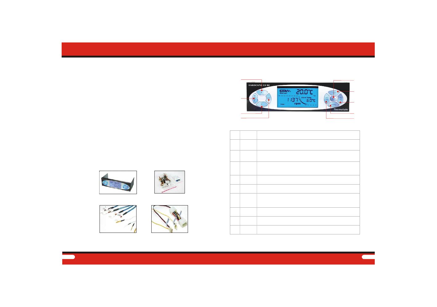
1 ) Overview
1
2
4
7
8
9
6
3
5
FunctionFunction
Key
FunctionFunction
Mode
+
-
Fan1/T1
Alarm
Fan2/T2
Fan3/T3
Fan4/T4
1
2
4
5
6
7
8
9
3
No .
OO
C/ F
3 ) Key Introduction
Introduction
1
1
While operating in Manual Mode, each time "+" button is pressed, the
corresponding fan will increase by ~3.125% of its maximum speed.
(This function is disabled while operating in Automatic Mode.)
To toggle between Automatic and Manual Mode (Default: Automatic)
While operating in Manual Mode, each time "-"button is pressed,
the corresponding fan will decrease by ~3.125% of its maximum
speed.
Mode. **Minimum fan speed is 50% of its maximum speed)
(This function is disabled while operating in Automatic)
To toggle between Celsius and Fahrenheit display mode.
(Default: Celsius)
To display Fan Speed, Temperature and Alarm setting corresponding
toFAN1/T1. (FAN1/T1 is the default after each computer restart)
To set the threshold at which alarm will sound to notify users about
high temperature.
*Default: 60 . ** Preset Values: 40 , 50 , 60 , 70
, 122 , 140 , 158
O OOOO
C CCCC
OOOO
104FFFF
To display Fan Speed, Temperature and Alarm setting
corresponding to FAN2/T2.
To display Fan Speed, Temperature and Alarm setting
corresponding to FAN3/T3.
To display Fan Speed, Temperature and Alarm setting
corresponding to FAN4/T4.
Accessory Pack x 2
3 4
T1~T4
Fan1~Fan4
No. Icon
1
Mode State
2
3
4
5
XXXXRPM
6
Alarm temp.
1
4
5
2
3
6
Description
Displays the current mode which the module is operating under:
Auto (Automatic) / Manual
Displays current temperature
Temperature
Shows the current temperature monitoring location.
(Regardless of its current monitoring location, when one of the
threshold temperature is reached, module will sound and its
backlight will flash to alarm user.)
Shows the current fan speed monitoring location.
(Regardless of its currently monitoring location,
when one of the fan stops operating,
LCD will display "0000rpm" and buzzer will sound to alarm user.)
Displays fan RPM. (Round Per Minute.)
Displays the current temperature alarm threshold.
Introduction Introduction
4 ) Display Introduction
Connectors:
4pin connector
X1
3 pin to 4 pin
adaptor X1
Connectors:
Fan controller
X4
Connectors:
thermal probe
X4
For power supply
For VGA cooler
For CPU cooler
For power supply
For case environment
Example
Example
Example
Example
Example
Example
Example
Example
For VGA fan
For CPU fan
T1
T2
T3
T4
FAN1
FAN2
FAN3
FAN4
For power supply fan
For case fan
Inclusion:
3pin connector X4
thermal probe X4
4pin connector X1
Fan Control Connector
+12V +5V 4pin Power Connector
5 ) Connectors
Connect H12 Control Connector
1
5 6
Part II
Installation
Installation
Multiple pre-drilled mounting holes to
accommodate various 5.25" drive depth.
Application for all kinds case installation:
1 ) How to install in case.
Note:Strongly recommended connecting the power
connector to the PSU directly.
Example:
2 ) Fan control function
2.1 Power Connector
Power Cable Power Socket Connect to PSU
Connect to
HARDCANO 12 SE
1
8
1
7
Installation
Fan Control Wire X 4
Controller connection figure
Application:
Each set of Fan Control Cable is labeled as followed:
Fan1/Fan2/Fan3/Fan4
Each can be connected to 3pin fan connector.
Fan1
Fan2
Fan4
Fan3
2.2 Fan Connectors
2.3 How to install the connectors
2.3.1 Fan connector with RPM signal wire
( 1 ) With 3 pin connector
Example:
Red
+12V
Black
Ground
Yellow
Signal RPM
With 3 pin connector
Some fan unit may be using +12V +5V 4pin connector.
In order for Hardcano 12 module to control, you'll need to utilize this
included adaptor.
CPU Fan
Adaptor(3 pin to 4 pin)
Installation
Connecting Fans
Above application shows Fan1 Fan Control Cable connected to the most
common fan connector. This setup will allow Hardcano 12 to adjust fan
speed and receive RPM signal as well.(please refer Q&A Q5 )
( 2 ) With 4 pin connector and RPM signal wire
4 pin connector
PCB Fan Connector
Fan Monitor Connector
Fan1 Fan2 Fan3 Fan4
Fan4
Fan3
Fan2
Fan1
10
Installation
CPU Fan
Adaptor(3 pin to 4 pin)
9
4 pin connector
PCB Fan Connector
2.3.2 Fan connector without RPM signal wire
Case Fan
VGA card cooler
Fan connectors
A few variations of fan does not provide RPM signal.
In such cases, Hardcano 12 module can only control the
Fan's speed but not monitor its RPM.
Fan connector without
RPM signal wire
Select the Fan you wish to adjust.
Installation
2.4 How to read fan speed
Fan2/T2
Fan1/T1
Fan4/T4
Fan3/T3
11 12
Press "+"button to increase fan speed.
(Maximum speed varies from each different fan unit.)
Press on "-" to decrease fan speed. (Minimum speed is 50% of the
fan's maximum speed.)
Installation Installation
3 ) Temperature detect function
3.1 Thermal sensor
Thermal Sensor X 4
T1
T2
T4
T3
3.2 How to attach the thermal sensor
Application:
Hardcano 12 includes 4 sets of Thermal Probe.
Attach each Thermal Probe to different heat
sources with the included thermal tape.
Thermal Sensor Connection Figure
Example:
T4
T3
T2
T1
13 14
Installation
CPU cooler
detect CPU temp
VGA card cooler
detect VGA temp.
CPU fan
detect case
environment temp.
Power supply
detect PSU temp
CAUTION:
Avoid excessive pressure to the sensor
T1 T2 T4
T3
3.3 How to read temperature
Installation
4 ) Alarm function
4.1 How to set the Alarm temperature
Press the "Alarm" button repeatedly until your desired temperature is
shown on the LCD. (Default: 60 )
O
C
EX. This display shows Alarm temp.
at FAN/T160
O
C
Choose the parameter you wish to configure the alarm setting for.
Example T1 :
Example T1 :
15 16
While the computer is idling or , it is
recommended to switch operating mode to Automatic to minimize the
overall noise level.
under minor workloadWhile the computer is idling or under minor workload, it is
recommended to switch operating mode to Automatic to minimize the
overall noise level.
5 ) Auto and Manual Mode
Installation
5.1 How to distinguish Auto/Manual mode
(Alarm setting Temp.)(Environment Temp.)
(12V)
(6V)
Each fan's speed will be automatically adjusted according to each
preset location's temperature. Following chart represents the
approximate speed at which fan will be operating under at different
temperature.
Auto. Mode
(when you away from the computer or the system workload is minor )
While operating under Manual Mode, users may adjust the fan speed
manually by pressing on "+" button to increase or "-" button to decrease.
"+" KEY: Increase fan speed by 3.125% of its maximum RPM.
Maximum RPM will vary from different fan units.
"-" KEY: Decrease fan speed by 3.125% of its maximum RPM.
Lowest RPM is 50% of its maximum RPM.
Manual Mode
(when you are using the computer or the system workload is heavy )
Installation
5.2 How to set the mode
17 18
Part III
Q&A
Q&A
Q1:The Hardcano 12 Module does not come on after system is
Powered?
Ans: Please make sure the main power connector is connected to
Power Supply.
Make sure all connectors
are connected securely.
Q2: LCD does not display temperature?
Ans:1.Make sure its corresponding Thermal Probe is attached
correctly to the component you wish to monitor.
2. Examine the Thermal Probe to see if there is any cut or
Discontinuity!
Q3: LCD does not display fan RPM?
Ans:1.Make sure the cables are connected securely.
2.Verify the fan unit you are controlling & monitoring has RPM
signal capability. Majority of the 3 wire fan have RPM signal
capability, while 2 wire fans do not.
Q&A
19
Q&A
20
Fan Failure Display
In the event of a failure, Hardcano 12 unit will sound off alarm
and LCD will have the following RPM display: 0000.
Q4: Hardcano 12 unit is unable to adjust fan speed?
Ans: A portion of fan unit have built in fan speed control.
To allow Hardcano 12 to take control, certain steps need to be
Performed. ie. Insert jumper.
  • Page 1 1
  • Page 2 2
  • Page 3 3
  • Page 4 4
  • Page 5 5
  • Page 6 6
  • Page 7 7
  • Page 8 8
  • Page 9 9
  • Page 10 10
  • Page 11 11
  • Page 12 12

Thermaltake A2349 Datasheet

Type
Datasheet

Thermaltake A2349 is an intelligent fan control system designed to efficiently manage multiple fans inside a computer chassis, reducing noise while maintaining optimal cooling. It offers four channels of fan speed control, allowing manual adjustment of each fan or automatic adjustment based on temperature sensors. The device features a stylish front bezel design and a user-friendly interface with precision electronic buttons for easy operation.

Ask a question and I''ll find the answer in the document

Finding information in a document is now easier with AI