2
CAUTION
!
DO NOT BEGIN INSTALLATION UNTIL YOU READDO NOT BEGIN INSTALLATION UNTIL YOU READ
DO NOT BEGIN INSTALLATION UNTIL YOU READDO NOT BEGIN INSTALLATION UNTIL YOU READ
DO NOT BEGIN INSTALLATION UNTIL YOU READ
THE FOLLOWING PRECAUTIONS.THE FOLLOWING PRECAUTIONS.
THE FOLLOWING PRECAUTIONS.THE FOLLOWING PRECAUTIONS.
THE FOLLOWING PRECAUTIONS.
PRECAUTIONSPRECAUTIONS
PRECAUTIONSPRECAUTIONS
PRECAUTIONS
1.1.
1.1.
1.
Failure to turn off electric or main gas supply toFailure to turn off electric or main gas supply to
Failure to turn off electric or main gas supply toFailure to turn off electric or main gas supply to
Failure to turn off electric or main gas supply to
clothes dryer could cause personal injury and/orclothes dryer could cause personal injury and/or
clothes dryer could cause personal injury and/orclothes dryer could cause personal injury and/or
clothes dryer could cause personal injury and/or
property damage by shock, gas suffocation, fire,property damage by shock, gas suffocation, fire,
property damage by shock, gas suffocation, fire,property damage by shock, gas suffocation, fire,
property damage by shock, gas suffocation, fire,
and/or explosion.and/or explosion.
and/or explosion.and/or explosion.
and/or explosion.
2.2.
2.2.
2.
Do not use this control on circuits exceeding speci-Do not use this control on circuits exceeding speci-
Do not use this control on circuits exceeding speci-Do not use this control on circuits exceeding speci-
Do not use this control on circuits exceeding speci-
fied voltage. Higher voltage will damage the controlfied voltage. Higher voltage will damage the control
fied voltage. Higher voltage will damage the controlfied voltage. Higher voltage will damage the control
fied voltage. Higher voltage will damage the control
and may cause shock or fire hazard.and may cause shock or fire hazard.
and may cause shock or fire hazard.and may cause shock or fire hazard.
and may cause shock or fire hazard.
3.3.
3.3.
3.
NEVER USE FLAME OR ANY KIND OF SPARK TONEVER USE FLAME OR ANY KIND OF SPARK TO
NEVER USE FLAME OR ANY KIND OF SPARK TONEVER USE FLAME OR ANY KIND OF SPARK TO
NEVER USE FLAME OR ANY KIND OF SPARK TO
CHECK FOR GAS LEAKS–COULD CAUSE FIRECHECK FOR GAS LEAKS–COULD CAUSE FIRE
CHECK FOR GAS LEAKS–COULD CAUSE FIRECHECK FOR GAS LEAKS–COULD CAUSE FIRE
CHECK FOR GAS LEAKS–COULD CAUSE FIRE
AND/OR EXPLOSION.AND/OR EXPLOSION.
AND/OR EXPLOSION.AND/OR EXPLOSION.
AND/OR EXPLOSION.
4.4.
4.4.
4.
Do not use a control set for natural gas with LP gas,Do not use a control set for natural gas with LP gas,
Do not use a control set for natural gas with LP gas,Do not use a control set for natural gas with LP gas,
Do not use a control set for natural gas with LP gas,
or a control set for LP gas with natural gas. Personalor a control set for LP gas with natural gas. Personal
or a control set for LP gas with natural gas. Personalor a control set for LP gas with natural gas. Personal
or a control set for LP gas with natural gas. Personal
injury and/or property damage, gas suffocation, fire,injury and/or property damage, gas suffocation, fire,
injury and/or property damage, gas suffocation, fire,injury and/or property damage, gas suffocation, fire,
injury and/or property damage, gas suffocation, fire,
and/or explosion may result.and/or explosion may result.
and/or explosion may result.and/or explosion may result.
and/or explosion may result.
1.1.
1.1.
1.
Do not short out terminals on gas valve or primaryDo not short out terminals on gas valve or primary
Do not short out terminals on gas valve or primaryDo not short out terminals on gas valve or primary
Do not short out terminals on gas valve or primary
control to test. Short or incorrect wiring can causecontrol to test. Short or incorrect wiring can cause
control to test. Short or incorrect wiring can causecontrol to test. Short or incorrect wiring can cause
control to test. Short or incorrect wiring can cause
equipment damage, property damage, and/or per-equipment damage, property damage, and/or per-
equipment damage, property damage, and/or per-equipment damage, property damage, and/or per-
equipment damage, property damage, and/or per-
sonal injury.sonal injury.
sonal injury.sonal injury.
sonal injury.
2.2.
2.2.
2.
This control is not intended for use in locationsThis control is not intended for use in locations
This control is not intended for use in locationsThis control is not intended for use in locations
This control is not intended for use in locations
where it may come in direct contact with water.where it may come in direct contact with water.
where it may come in direct contact with water.where it may come in direct contact with water.
where it may come in direct contact with water.
Suitable protection must be provided to shield theSuitable protection must be provided to shield the
Suitable protection must be provided to shield theSuitable protection must be provided to shield the
Suitable protection must be provided to shield the
control from exposure to water (dripping, spraying,control from exposure to water (dripping, spraying,
control from exposure to water (dripping, spraying,control from exposure to water (dripping, spraying,
control from exposure to water (dripping, spraying,
rain, etc.).rain, etc.).
rain, etc.).rain, etc.).
rain, etc.).
WARNING
!
If you do not follow these instructions exactly, a fire or explosion
may result causing property damage, personal injury or loss of life.
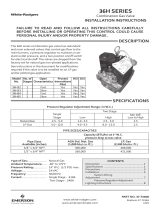
G
H
F
E (not shown)
C
B
D
B
A
C
E
Figure 1Figure 1
Figure 1Figure 1
Figure 1
Figure 2Figure 2
Figure 2Figure 2
Figure 2
INSTALLATIONINSTALLATION
INSTALLATIONINSTALLATION
INSTALLATION
1. Before attempting to service dryer, unplug power cord,
turn off main gas supply and consult dryer manufactur-
er's instructions for accessing gas valve.
2. Disconnect exhaust vent duct.
3. Disconnect gas line from rear of dryer.
4. Remove access panel from dryer. On some models this
involves removing the entire front panel.
5. The gas valve/burner assembly should now be visible.
6. The burner assembly consists of (see figure 1 & 2):
a. Gas inlet pipe.
b. Brass inlet fitting with union – some models may also
have a manual shut-off valve.
c. Gas valve.
d. Mounting bracket.
e. Burner orifice.
f. Burner assembly with air shutter.
g. Igniter.
h. Radiant sensor – located on heat exchanger on
some models.
7. Disconnect the wiring harness from gas valve and
igniter.
8. Remove screw(s) fastening the mounting bracket to the
bottom of dryer.
9. Burner assembly should now be free to slide out of the
front of dryer. Take care not to bump or jar igniter. It is
very fragile.
10. Remove the gas inlet pipe by unscrewing the union.
11. Remove screw(s) fastening the gas valve to the mount-
ing bracket and set them aside. They will be reused.