Page is loading ...

500 Series Metering Flow Switches
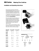
This document provides basic information
describing the plumbing and electrical connections,
and trip point adjustments to install and make
operational your 500 Series Metering Flow Switch.
A comprehensive Technical Reference Manual
for these devices is available on the Proteus
Industries website at
www.proteusind.com/500
.
This manual includes technical descriptions,
performance specifications, dimensions, detailed
drawings, trip-point tables, flow response graphs
and tables, maintenance instructions, product
warranty, and part numbers for replacement parts.
Model No. Flow Range Flow Range
LPM GPM
0504SN2
0.95 – 9.5 0.25 – 2.5
0504SA2
0504SN4
1.1 – 17 0.3 – 4.5
0504SA4
Model Number Structure
500 Series
Flow body material
S = stainless steel
Maximum flow
rate in GPM
Thread type
N = FNPT
A = SAE
Connection size
04=
1
⁄
4
"
05 04 S N 4
SETUP GUIDE

Connect plumbing
• Do NOT exceed the maximum temperature or pressure
limits of the sensor.
• If fluid temperature will exceed 85 °C, the electronics
must be isolated from the flow sensor.
1. Identify the type and size of plumbing connections
from the Model Number Table on page 1.
Do NOT exceed the flow limit of your flow sensor!
2. Use Teflon tape or paste to lubricate and seal NPT threads.
Use a high-pressure lubricant to lubricate SAE threads.
3. Turn on your liquid flow slowly, and check for leaks at
the two connections. Tighten connections as required
to eliminate all leaks.
1
Make electrical connections
1. Locate the source of 24 VDC power and turn it OFF.
2. Prepare wiring cables of up to #16 gauge to connect
power and the required relay and voltage outputs.
3. Connect the flow switch common wire in position 5.
4. For a N.C. relay state, connect the other flow switch
wire in position 4.
For a N.O. relay state, connect in position 6.
5. Connect the power common wire to position 2.
6. Connect the +24 VDC wire to position 1.
7. Connect to the 24 VDC source and turn it ON.
• If liquid is NOT flowing, the LED will show RED,
indicating power is on and liquid flow is below the
selected trip-point flow rate.
• Ifliquidisflowing,theLEDmayshowGREEN,
AMBER, or RED, depending on flow rate and the
selected trip-point flow rate, as described in Table 1
on page 4.
2

Select trip point
1. From the Trip Point Table (Table 2) on page 4, select
the row with the Model Number of your flow sensor.
2. Look ACROSS the table to select your desired trip
point.
3. Look UP the table to identify the setting of the
16-position switch for your trip point.
4. Set the 16-position switch so that the arrow points
towards the setting you selected in step three.
5. Set the fine-adjustment potentiometer to the
12 o’clock position.
Refer to the 500 Series Technical Reference Manual
for use of the fine trip-point adjustment feature.
3
Measure flow
1. Read the voltage between positions 2 and 3 with a
voltmeter.
2. Refer to the calibration certificate provided with your
flow sensor or to the Flow Response Curves (Figure 1)
on page 4 to identify the actual flow rate.
4

LED Color Flow Rate Status Example Trip Point Relay State
1.0 GPM N.O. contact N.C. contact
Green Greater than 1.15 x Actual Flow > 1.15 GPM Closed Open
flow rate at selected trip point
Amber Between 1x and 1.15 x 1.0 < Actual Flow < 1.15 GPM Closed Open
flow rate at selected trip point
Red Less than flow rate Actual Flow < 1.0 GPM Open Closed
at selected trip point
Model Switch Position
Number
0 1 2 3 4 5 6 7 8 9 A B C D E F
0504SN2 0.15 0.29 0.44 0.59 0.74 0.88 1.03 1.18 1.32 1.47 1.62 1.76 1.91 2.06 2.21 2.35
0504SA2
0504SN4 0.26 0.53 0.79 1.06 1.32 1.59 1 .85 2.12 2.38 2.65 2.91 3.18 3.44 3.70 3.97 4.23
0504SA4
0
1
2
3
4
5
01234
Flow Rate - GPM
Output - VDC
0504SN2
0504SA4
0504SN2
0504SA2
Figure1: Flow Response Curves
Table 1: LED Color, Flow Rate and Relay State
Table 2: Selecting Trip-Point Flow Rate with 16-position Switch Units: US gallons per minute (1 US gallon = 3.785 liters)
Note: The trip-point flow rates in the table above are calculated values. Custom factory trip-point setting is available to achieve stated accuracy.
The presence of elbows or devices other than straight fittings installed at the inlet may affect the actual trip-point settings.
Information in this document was correct at the time of
printing; however, specifications are subject to change as
Proteus Industries’ continuous improvement processes
establish new capabilities.
© Proteus Industries Inc. All rights reserved. All other
company and product names may be trademarks of their
respective companies.
500SG Rev 002 08/2016
/


