Page is loading ...

MKII-Axx Installation Guide
32-0068-r03 1 / 3 17/10/2017
Zeta Alarms Limited, 72/78 Morfa Road, Swansea, SA1 2EN
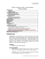
Typical Wiring Diagram
Note: Polarity must be observed on detector as indicated on schematic wiring diagram.
Earth terminal is provided to maintain earth screen continuity. It does not connect to this detector head.
Base Installation
Connect the zone wires to the appropriate terminal. Tighten with a correct sized screwdriver: a wrong screwdriver may damage the screw
heads.
Make sure that the base contacts are clean and unobstructed.
Note, the base model No. for MKII-A Series is MKII-CB or MKII-CB/D.
Detector Head Installation
If there is still minor construction work in progress, the head may be fitted, provided that the dust cover is still in place.
To fit the detector, mate the detector onto the base and rotate the detector in clockwise until the detector loads into the base.
Continue to twist clockwise to secure it.
Model List
Specifications
Electrical Characteristics
Parameter
Loop voltage
17 V – 28 V DC
Maximum current consumption, at 24 VDC
Switch-on surge, max 65 ms
Quiescent
Alarm (with no remote output.)
800uA
500uA
5mA
Remote Output Capacity
Vloop@5mA
Startup Time
15S
Maximum cable resistance
50Ω
Environmental
Operating temperature
-10 °C to + 80 °C
Operating humidity
0-95% RH
(no condensation or icing)
Design environment
Indoor use only
IP Rate
42
Part No
Model No.
Description
CPR No.
LPCB No
80-210
MKII-AOP
Analogue optical detector
0832-CPR-F0075
330n/02
80-212
MKII-AHR
Analogue A1R heat detector
0832-CPR-F0079
330q/04
80-214
MKII-AHF
Analogue A2S heat detector
0832-CPR-F0081
330q/03
80-216
MKII-AOH
Analogue optical and A1 heat detector
0832-CPR-F0077
330p/02
80-218
MKII-AHF/CS90
Analogue CS heat detector
0832-CPR-F1921
330q/05

MKII-Axx Installation Guide
32-0068-r03 2 / 3 17/10/2017
Zeta Alarms Limited, 72/78 Morfa Road, Swansea, SA1 2EN
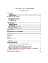
Detector Address Setting
Each detector fitted to the loop needs to have a unique
address set. There can only be one device set to each
address.
The address is set with a dip switch located on the
underside of the detector. There are 8 switches.
Switches 1 to 8 are used to set a binary address, with
the ON position being binary 0 (0 marked on the label),
and the OFF position being binary 1. (1 marked on the
label)
Addresses 0 (all ON) and 255 (all OFF) are not used.
The address can be set by following the table opposite,
or by following equation
Switch 1 OFF = add 1 to total
Switch 2 OFF = add 2 to total
Switch 3 OFF = add 4 to total
Switch 4 OFF = add 8 to total
Switch 5 OFF = add 16 to total
Switch 6 OFF = add 32 to total
Switch 7 OFF = add 64 to total
Switch 8 OFF = add 128 to total
ADDR
87654321
ADDR
87654321
ADDR
87654321
ADDR
87654321
N/A
00000000
32
00100000
64
01000000
96
01100000
1
00000001
33
00100001
65
01000001
97
01100001
2
00000010
34
00100010
66
01000010
98
01100010
3
00000011
35
00100011
67
01000011
99
01100011
4
00000100
36
00100100
68
01000100
100
01100100
5
00000101
37
00100101
69
01000101
101
01100101
6
00000110
38
00100110
70
01000110
102
01100110
7
00000111
39
00100111
71
01000111
103
01100111
8
00001000
40
00101000
72
01001000
104
01101000
9
00001001
41
00101001
73
01001001
105
01101001
10
00001010
42
00101010
74
01001010
106
01101010
11
00001011
43
00101011
75
01001011
107
01101011
12
00001100
44
00101100
76
01001100
108
01101100
13
00001101
45
00101101
77
01001101
109
01101101
14
00001110
46
00101110
78
01001110
110
01101110
15
00001111
47
00101111
79
01001111
111
01101111
16
00010000
48
00110000
80
01010000
112
01110000
17
00010001
49
00110001
81
01010001
113
01110001
18
00010010
50
00110010
82
01010010
114
01110010
19
00010011
51
00110011
83
01010011
115
01110011
20
00010100
52
00110100
84
01010100
116
01110100
21
00010101
53
00110101
85
01010101
117
01110101
22
00010110
54
00110110
86
01010110
118
01110110
23
00010111
55
00110111
87
01010111
119
01110111
24
00011000
56
00111000
88
01011000
120
01111000
25
00011001
57
00111001
89
01011001
121
01111001
26
00011010
58
00111010
90
01011010
122
01111010
27
00011011
59
00111011
91
01011011
123
01111011
28
00011100
60
00111100
92
01011100
124
01111100
29
00011101
61
00111101
93
01011101
125
01111101
30
00011110
62
00111110
94
01011110
126
01111110
31
00011111
63
00111111
95
01011111
127
01111111
128
10000000
160
10100000
192
11000000
224
11100000
129
10000001
161
10100001
193
11000001
225
11100001
130
10000010
162
10100010
194
11000010
226
11100010
131
10000011
163
10100011
195
11000011
227
11100011
132
10000100
164
10100100
196
11000100
228
11100100
133
10000101
165
10100101
197
11000101
229
11100101
134
10000110
166
10100110
198
11000110
230
11100110
135
10000111
167
10100111
199
11000111
231
11100111
136
10001000
168
10101000
200
11001000
232
11101000
137
10001001
169
10101001
201
11001001
233
11101001
138
10001010
170
10101010
202
11001010
234
11101010
139
10001011
171
10101011
203
11001011
235
11101011
140
10001100
172
10101100
204
11001100
236
11101100
141
10001101
173
10101101
205
11001101
237
11101101
142
10001110
174
10101110
206
11001110
238
11101110
143
10001111
175
10101111
207
11001111
239
11101111
144
10010000
176
10110000
208
11010000
240
11110000
145
10010001
177
10110001
209
11010001
241
11110001
146
10010010
178
10110010
210
11010010
242
11110010
147
10010011
179
10110011
211
11010011
243
11110011
148
10010100
180
10110100
212
11010100
244
11110100
149
10010101
181
10110101
213
11010101
245
11110101
150
10010110
182
10110110
214
11010110
246
11110110
151
10010111
183
10110111
215
11010111
247
11110111
152
10011000
184
10111000
216
11011000
248
11111000
153
10011001
185
10111001
217
11011001
249
11111001
154
10011010
186
10111010
218
11011010
250
11111010
155
10011011
187
10111011
219
11011011
251
11111011
156
10011100
188
10111100
220
11011100
252
11111100
157
10011101
189
10111101
221
11011101
253
11111101
158
10011110
190
10111110
222
11011110
254
11111110
159
10011111
191
10111111
223
11011111
N/A
11111111

MKII-Axx Installation Guide
32-0068-r03 3 / 3 17/10/2017
Zeta Alarms Limited, 72/78 Morfa Road, Swansea, SA1 2EN
Maintenance Information
Fyreye Mk II detectors are generally installed as part of a fire alarm system.
Servicing of the system should be carried out in accordance with the requirements of the local code of practice for fire alarm installations,
eg. BS 5839 Part 1, Fire Detection and Alarm Systems for Buildings: Code of Practice for System Design, Installation and Servicing.
The frequency of inspection testing will be based on a risk assessment of the installation, but should be no more than 6 months between
visits.
Over a 12 month period every detector should be functionally tested, using suitable equipment to generate smoke or heat (EG the Solo
range from No Climb Products)
Cleaning
Cleaning a smoke detector can prolong its working life. The detector can be cleaned with:-
A hand held vacuum cleaner
A clean air line or a “duster” aerosol
A lint free cloth.
The effectiveness of cleaning will depend on the operating environment of the detector.
Depending on timescales & financial considerations, detector cleaning may not be a practical option.
When to replace a detector
A detector should be considered as needing to be replaced if:-
The detector does not respond to a functional test
If the detector has had an unexplained activation*
If the detector has been in service for more than 10 years**
* In some cases it may be sensible to leave a detector until a second unexplained activation, but consider the extra service costs and
perceived system integrity if this is done.
** Many detectors will continue to function adequately way beyond 10 years service. Balance the frequency of unwanted alarms, with the
cost of replacing detectors when making this decision.
0832
Zeta Alarms Limited,
72-78 Morfa Road, Swansea SA1 2EN
17
0832-CPR-F0075/F0077/F0079/F0081/F1921
EN54-5:2000+A1:2002
Heat detectors — Point detectors
EN54-7:2000+A1:2002 + A2: 2006
Smoke detectors — Point detectors using scattered light,
transmitted light or ionization
MKII Addressable detectors
MKII-AOP, MKII-AOH, MKII-AHR, MKII-AHF, MKII-AHF/CS90
Other Technical Data: See Doc: “MKII-AXX LPCB, MKII-AXX/CS LPCB”
held by the manufacturer
/