
ge.com
Safety information ............. 2
installation Instructions ...s-12
Step-bg-step instructions ....... 6-12
Operating Instructions
Breaking a salt bridge ............. !a
Cleaning the nozzle and
venturi assemblg ................. 14
Features ...................... 15, !6
Service .................... 13, 16-20
Water softener sgstem ........ 13-21
Care and Cleaning ............ 22
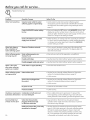
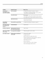
Troubleshooting Tips ...... 23-25
Consumer Support
Consumer Support ....... Back Cover
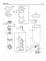
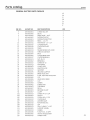
Parts list/catalog .............. 27-30
Warrantg ........................ 31
Water Softening
Sgstem
Model GNSM48F
System tested and certified by NSFInternational against NSF/ANSIStandard 44 for the
chemical reduction claims specified on the performance data sheet.
Write the model and serial
numbers here:
Model #
Serial #
You can find them on the
back of the control head.
7289362 215Cl173P024 49-50179 07-06 JR

IMPORTANT SAFETY INFORMATION.
READ ALL INSTRUCTIONS BEFORE USING.
;i WARNING!
For your safety, the information in this manual must be followed to minimize the risk of electric
shock, property damage or personal injurg.
SAFETYPRECAUTIONS
::Ji::Check and complg with gour state and local codes.
You must follow these guidelines.
::Ji::Use care when handling the water softening
sgstem. Do not turn upside down, drop, drag
or set on sharp protrusions.
?_:Water softening sgstems using sodium chloride
(salt) for recharge add sodium to the water.
Persons on sodium restricted diets should consider
the added sodium as part of their overall intake.
Potassium chloride can be used as on alternative
to sodium chloride in your softener.
?_:The water softening sgstem works on 24 volt-60 Hz
electrical power onlg. Be sure to use only the
included transformer.
::Ji::Use clean water softening salts onlg, at least 99.5%
pure. NUGGET,PELLETor coarse SOLARsalts are
recommended. Do not use rock, block, granulated
or ice cream making salts. Theg contain dirt and
sediments, or mush and cake, and will create
maintenance problems.
::J_::Keep the salt hole cover in place on the softener
unless servicing the unit or refilling with salt.
WARN ING: DOnot usewith water that
is microbiologicallg unsafe or of unknown qualitg
without adequate disinfection before or after the
sgstem.
iJi::Transformer must be plugged into an indoor
120 volt, grounded outlet onlg.
PROPERINSTALLATION
This water softening system must be properlg installed and located in accordance with the
Installation Instructions before it is used.
?_:Install or store where it will not be exposed to
temperatures below freezing or exposed to ang
tgpe of weather. Water freezing in the sgstem will
break it. Do not attempt to treat water over 100°R
::J_::Do not install in direct sunlight. Excessivesun or
heat mag cause distortion or other damage to
non-metallic parts.
?_:Properlg ground to conform with all governing
codes and ordinances.
!;_:Use onlg lead-free solder and flux for all
sweat-solder connections, as required bg
state and federal codes.
?_:Softener resins mag degrade in the presence of
chlorine above 2 ppm. If gou have chlorine in excess
of this amount, gou mag experience reduced life
of the resin. In these conditions, gou mag wish to
consider purchasing a GEpoint-of-entrg household
filtration sgstem with a chlorine reducing filter.
A WARNING: Discard all unused parts
and packaging material after installation. Small
parts remaining after the installation could be
a choke hazard.
Thewater softening sgstem requires a minimum
water flow of three gallons per minute at the inlet.
Maximum allowable inlet water pressure is 125 psi.
If dagtime pressure is over 80 psi, nighttime pressure
mag exceed the maximum. Usea pressure reducing
valve to reduce the flow if necessarg.
READAND FOLLOWTHISSAFETYINFORMATIONCAREFULLY.
SAVETHESEINSTRUCTIONS

iJns'a"a,ionIwaterso'teninosystemI
nstructlons Model GNSM48F
I r_ Questions? Call 800.GE.CARES (800.432.2737) or Visit our Website at: ge,com I
WARN ING: Read entire manual. Failure to follow all guides and rules could cause personal
injurg or propertg damage.
• Check with gour state and/or local public works department for plumbing codes. You must follow their
guides as gou install the Water Softening sgstem.
NOTE: Failure to complg with these installation instructions will void the product warrantg, and the
installer will be responsible for ang service, repair or damages caused therebg.
BEFORE BEGINNING INSTALLATION
Read these instructions completelg and carefullg.
• IMPORTANT - savetheseinstructions
for local inspector's use.
• IMPORTANT - Observeallgoverning
codes and ordinances.
• Note to Installer- Be sure to leave these
instructions with the Consumer.
• Note to Consumer- Keep these instructions
for future reference.
• Proper installation is the responsibilitg of the
installer.
• Product failure due to improper installation
is not covered under the Warrantg,
• A shutoff valve must be available or added near
the installation point.
IMPORTANT INSTALLATION
RECOMMENDATIONS
• In the Commonwealth of Massachusetts,
Plumbing Code 248 CMR shell be adhered to.
Consult with gour licensed plumber.
• Use onlg lead-free solder and flux for all sweat-
solder connections, as required bg state and
federal codes.
• Connect the softener to the main water supplg
pipe before or ahead of the water heater.
DO NOT RUN HOT WATER THROUGH THE
SOFTENER. Temperature of water passing
through the softener must be less than 120°F.
IMPORTANT INSTALLATION
RECOMMENDATIONS (CONT.)
• Use care when handling the softener. Do not
turn upside down, drop, drag or set on sharp
protrusions.
Maximum allowable inlet water pressure is 125
psi, If dagtime pressure is over 80 psi, nighttime
pressure mag exceed the maximum. Use a
pressure reducing valve if necessarg, (Adding a
pressure reducing valve mag reduce the flow.)
The softener works on 24 volt-60 Hz electrical
power onlg. Be sure to use the included
transformer. Be sure the electric outlet and
transformer are in an inside location to protect
from moisture.
• See Where to Install the Softener section
for more details.
AWARNI NG:Do not use with water
that is microbiologicallg unsafe or of unknown
qualitg without adequate disinfection before or
after the system, The water should be tested
periodicallg to verify that the system is
performing satisfactorily,
• Small parts remaining after the installation could
be a choke hazard. Discard safelg.

Installation Instructions
UNPACKING AND INSPECTION
Be sure to check the entire softener for ang
shipping damage or parts loss. Also note damage
to the shipping cartons. Contact the transportation
compang for all damage and loss claims. The
manufacturer is not responsible for damages
in transiL
Small parts needed to install the softener are
packaged either in a bag or on a cardboard
sheet. To avoid loss of the small parts, keep them
packaged until gou are readg to use them. Be sure
not to discard components hidden in packaging.
TOOLS AND MATERIALS REQUIRED
FOR INSTALLATION
• Pliers
Screwdriver
• Teflon tape
• Razor knife
Two adjustable wrenches
• Additional tools may be required if modification
to home plumbing is necessarg.
In and out fittings included with the softener are
!" NPT male adapters. You should maintain the
same, or larger, pipe size as the water supplg
pipe, up to the softener inlet and outlet. Then,
use the necessarg adapters to connect the water
supplg to the !" NPT male adapters.
Use the included bgpass valve to install the
softener. The bgpass valve allows gou to turn off
water to the softener for servicing, but still have
water in the house pipes. The in and out fittings
referred to above connect to the bgpass valve
with the included bgpass clips.
• Use appropriate fitting/pipe material (i.e.,copper,
brass, galvanized or CPVC) to connect the !" NTP
plastic adapters to the house plumbing.
• If additional drain hose is needed for valve and
salt tank drains, it can be ordered from GE Parts
at 800.626.2002, part number WS07X!0004.
If a rigid valve drain is needed to complg with
plumbing codes, gou can bug the parts needed
to connect a 1/2" copper tubing or plastic pipe
drain. See Step S.
Clean nugget or pellet water softener salt is
needed to fill the brine tank. See Step 11.
WHERE TO INSTALL THE SOFTENER
Place the softener as close as possible to a
sewer drain, or other acceptable drain point
or standpipe.
It is recommended to keep outside faucets
on hard water to save soft water and salt.
Do not install the softener in a place where it
could freeze. Freeze damage is not covered bg
the warrantg.
Do not install the softener where it would block
access to the water heater or access to the main
water shutoff.
Putthe softener in a place where water damage
is least likelg to occur if a leak develops. The
manufacturer will not repair or pag for water
damage.
A &20-volt electric outlet is needed to plug in the
included transformer. The softener has a !0-foot
power cable. If the outlet is remote (up to !00
feet), use 18 gauge wire to connect. Be sure the
electric outlet and transformer are in an inside
location, to protect from wet weather. Be sure
the outlet is unswitched to prevent accidental
shutoff.
If installing in an outside location, gou must
take the steps necessarg to assure the softener,
installation plumbing, wiring, etc., are as well
protected from the elements (sunlight, rain, wind,
heat, cold), contamination, vandalism, etc., as
when installed indoors. Outdoor installation is
not recommended, and voids the warrants.
Keep the softener out of direct sunlight.
The sun's heat mag distort non-metallic
parts and mag damage the electronics.

Installation Instructions
PLAN HOW YOU WILL INSTALL THE
SOFTENER
You must first decide how to run in and out pipes
to the softener. Look at the house main water pipe
at the point where gou will connect the softener.
Is the pipe soldered copper, glued plastic or
threaded galvanized2 What is the pipe size2
kWARNING: Use onlg lead-free solder and
flux to prevent lead poisoning,
See Tgpicaf Installation Illustration. Use this as a guide
when planning gour particular installation. Be sure
to direct the incoming hard water supply to the
softener valve inlet fitting. The valve is marked
IN and OUT.
TYPICAL INSTALLATION ILLUSTRATION
O-rings (2)
J
Brine
tank
NOTE: See Drain
Hose Connections
section.
Fig. 1
CROSSOVER
Use if water supply flows
from the left. Include single
or 3-valve bypass.
water
From
softener t
outlet
Soft
water
To softener
inlet
OPTIONAL 3-VALVE BYPASS
INSTALLATION ILLUSTRATION
Soft water MAIN
Hard water
to outside
Pip E faucets
24V
transformer
120-volt
outlet
Inlet
valve
Hard
water
1" NPT male
pter (2)
_, O-rings (2)
INLET Clips (2)
Brine tank
Fig. 2
CROSSOVER
Use if water supply flows
from the left. Include single
or 3-valve bypass.
Hard
water (_ !:--::L-{2:::
From
softener t
outlet Z_
Soft
water
D
To softener
inlet

Installation Instructions
BEFORE YOU BEGIN
• Turn off the gas or electric supplg to the water
heater, in the possibilitg that the water heater
mag be drained while draining pipes.
• Turn off the water supplg to pipes to be cut and
drain the house water pipes.
• Open both hot and cold faucets at the lowest
location possible.
NOTE: For easier installation, remove the top cover.
Release 2 clips at rear of cover. Rotate cover
forward and lift up.
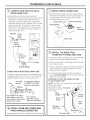
_1 INSTALL BYPASS VALVE
• Remove plastic shipping plug and wire from valve
outlet.
Turbine
_ Valve outlet
Turbine shaft and
• support
NOTE: Be sure the turbine and support are firmlg
in place in the valve outlet. Blow into the valve port
and observe the turbine for free rotation.
• Push the bgpass valve (lubricate o-ring seals with
silicone grease) into both ports of the valve as
shown.
Clips
/ NPT adapter
O-ring seal goes into the outer
groove only. The clip snaps into
the inner groove (see below).
• Snap the 2 large plastic clips in place, from the
top down, as shown.
SIDE Clip
VIEW END
VIEW
Valve bad, Bypass valve
inlet or push all the way in)
• Push the NPT adapters (lubricate o-ring seals with
silicone grease) into both ports of the valve as
shown.
[_ INSTALL DRAIN FITTING
• Push the drain fitting (lubricate o-ring seals
with silicone grease) into the part of the valve
as shown.
Snap the large plastic clip in place, from the
top down as shown. Be sure the clip snaps into
place. Pull on the drain fitting to make sure it is
held securely in place.
Drain fitting
[3] MOVE THE SOFTENER ASSEMBLY
INTO INSTALLATION POSITION
CAUTION:
• Secure the resin tank to a stable structure to
prevent it from fulling over.
• Locate the brine tank directlg next to the resin
tank.
Be sure the installation surface is level and
smooth. Sharp objects under the brine tank mag
puncture it. If needed, place the brine tank on a
section of 3/4" thick (minimum) plgwood. Then,
place shims under the plgwood as needed to
level the softener.
• Connect the black brine valve tube from the
brinewell to the venturi assemblg on the valve,
using the plastic nut provided.
• Snap the 2 large plastic clips in place, from the
side, as shown. 6

Installation Instructions
141 PLUMB "IN" AND "OUT" PIPES
TO AND FROM SOFTENER
CAUTION: Observe all of the following
cautions as gou connect inlet and outlet
plumbing. See Typical Installation Illustration.
• BESURE INCOMING HARD WATER SUPPLY IS
DIRECTEDTO THE SOFTENER VALVE INLET PORT.
If house water flow is from the left, use a
plumbing crossover as shown in Typical
Installation Illustration. If house water flows up
from the floor level, turn the bgpass valve upside
down as shown.
Turn bypass
valve upside
down to
connect to
floor level
IN plumbing
• With the softener in place, determine the correct
length of piping required to connect the household
plumbing to the NPT male adapten
• Remove softener from installation space.
• If making a soldered copper installation, do all
sweat soldering before connecting pipes to the
NPT adapters and bypass valve. Torch heat will
damage plastic parts.
• When turning threaded pipe fittings onto plastic
fittings, use care not to cross-thread.
• Use Teflon Tape on all external pipe threads.
• Support inlet and outlet plumbing in some manner
(use pipe hangers) to keep the weight off of the
valve fittings.
• Slide softener back into position.
• Hake final connections to the bgpass valve and
snap clips into place.
Be sure the clips for the bypass valve and NPT
adapters snap into place. Pull on the bypass valve
and NPT adapters to make sure the parts are held
securely in place.
151 CONNECT AND RUN THE VALVE
DRAIN HOSE
IMPORTANT: If gou want to attach the drain fitting
to a rigid tube, see Connecting a Rigid Valve Drain
Tube section on next page.
• Use the provided drain hose (20' length included)
to attach to the valve drain fitting. To keep water
pressure from blowing the hose off, use supplied
spring clamp to secure in place. Cut the necessarg
length and use the remainder in Step 8.
1/4" NPT thread
Barbs for 3/8" I.D. tubing
ose clamp
Drain hose
• Locate the other end of the hose at a suitable
drain point (floor drain, sump, laundrg tub, etc.)
that terminates at the sewer. Check and complg
with local codes.
IMPORTANT: If more drain hose is needed, it
should be ordered from GE Parts at 800.6262002,
part number WS07X10004. The water softener will
not work if water cannot exit this hose during
recharge.
Tie or wire the hose in place at the drain point.
High water pressure will cause it to whip during
the back-wash and fast rinse cgcles of recharge.
Also provide an air gap of at least 1-1/2"
between the end of the hose and the drain
point. An air gap prevents possible siphoning of
sewer water into the softener, if the sewer should
"back-up."

Installation Instructions
[_ CONNECT AND RUN THE VALVE
DRAIN HOSE ICONT.i
• Elevating the drain hose mag cause back
pressure that could reduce the brine draw during
recharge. If raising the drain line overhead is
required to get to the drain point, measure the
inlet water pressure to the softener first. For inlet
pressures between 20 and 50 psi, do not raise
higher than 8' above the floor. For inlet pressure
above 50 psi, the drain line mag be raised to a
maximum height of 14'.
Fig. 4A Valve
drain
hose
! P /' ". g_I_
STANDPIPE
11½"air gap
FLOOR DRAIN
CONNECTING A RIGID VALVE DRAIN TUBE
To adapt a copper drain tube to the softener, bug a
compression fitting (1/4 NPT x 1/2" O.D. tube) and
needed tubing from gour local hardware store.
1/4" NPT
thread
Compression fitting
1/4 NPT x 1/2" O.D.
tube (not provided)
/
I
Cut barbs from valve
drain elbow (pull clip
and remove drain valve
elbow from valve)
1/2" outside
diameter copper
tube (not provided)
[6] INSTALL TIMER AND COVERS AND
MAKE HARNESS CONNECTION
_f] BRINE TUBING CONNECTION
• Route the brine tubing out of the largest hole in
the brine tank sidewall. Use the compression nut
(in parts bag) to connect tubing to the nozzle
assemblg at the main valve.
Compression nut Nozzle assembly
Brine tubing
assembly
Brine tank
J
I8] INSTALL THE BRINE TANK
OVERFLOW FITTINGS AND HOSE
• Insert the rubber grommet into the 3/4" diameter
hole in the brine tank sidewall as shown.
Push the end of the hose adapter elbow into the
grommet as shown.
Attach a length of hose (use remaining hose from
Step 5) to the hose adapter elbow. Use a hose
clamp to hold it in place.
Locate the other end of the hose at the drain
point. DO NOT ELEVATEthis hose higher than the
elbow on the brine tank.
IMPORTANT: DO NOT TEE OVERFLOW HOSE
TO VALVE DRAIN HOSE.
NOTE: This drain is for safetg onlg. If the cabinet
(brine tank) should
over-fill with water, Grommet
the excess is carried
to the drain.
Hose
adapter'_ Venturi
nozzle
Overflow
drain hose
Brine
tank
I -. ..... -÷
To sewer drain
See separate instructions included in box with parts.
8

Installation Instructions
19] INSTALL GROUNDING CLAMP
-ADANGER: Failure to properly attach
ground clamp could result in electrical shock.
If plumbing is metal, to maintain electrical ground
continuity in the house cold water piping, install the
included ground clamp as shown.
• Clean pipe with emery paper in the area where
the clamp is to be installed.
Install grounding clumps us shown, making sure
clamps fit freely around pipe.
Make sure lock washer is in place.
Hundtighten screw, then one more full turn with
screwdriver.
NOTE: When replacing an existing softener, also
replace grounding clamps. If removing softener
completely, hard-plumb the water line with same
type of pipes as the original to assure plumbing
integrity and ground continuity over the life of
the home. To valve inlet
Ground
Clamp
Q
_ Fo_ee_tvalve
I_ FLUSH PIPES, EXPEL AIR FROM
SOFTENER AND TEST YOUR
INSTALLATION FOR WATER LEAKS
-ACAUTION: Toavoidwateror air
pressure damage to softener inner parts, be
sure to do the following steps in exact order.
• Fully open 2 cold soft water faucets nearby
the softener.
• Place bypass valve in "bypass" position bg
pushing the stem inward.
• Fully open the house main water pipe shutoff
valve. Observe a steady flow from both faucets
opened above.
I_ FLUSH PIPES, EXPEL AIR FROM
SOFTENER AND TEST YOUR
INSTALLATION FOR WATER
LEAKS ICONT.)
• Place bypass valve in the "service" position
EXACTLY as follows. KEEP SOFT WATER FAUCETS
OPEN.
SLOWLY pull or slide the valve stem (out) toward
the service position, pausing several times to
allow the softener to pressurize slowly.
After about 3 minutes, open a HOT water faucet
for 1 minute, or until all air is expelled, then
close. NOTE: If water appears cloudy or has salty
taste, allow to run for several more minutes, or
until clear.
• Close all water faucets.
Check your plumbing work for leaks and fix
right away if any are found. Be sure to observe
previous caution notes.
Turn on the gas or electric supply to the water
heater. Light the pilot, if applicable.
I_] ADD WATER AND SALT TO THE
BRINE TANK
• Lift the salt hole cover. Add about 3 gallons of
water into the tank. Do not add into the brinewell.
Fill tank with NUGGET, PELLETor coarse SOLAR
water softener salt with a purity of 99.5% or
higher. Do not use rock, block, granulated and ice
cream-making salts, or salt with iron-removing
additives (except for Diamond Crystal ®Red•Out ®
brand salt). Maximum salt storage capacity is
approximately 200 Ibs. Keep the salt hole cover
closed unless servicing the unit or refilling
with salt.
NOTE: If the softener is installed in a humid
basement or other damp area, it is better to fill the
tank with less salt, more frequently. Eighty to 100
Ibs. of salt will last for several months, depending on
water hardness, family size and water softening
system model.

Installation Instructions
[] CONNECT TO ELECTRICAL POWER
To gain access to the transformer/power cord
assemblg, remove the salt hole cover from the
softener. Unclip the tabs on the rear of the top cover
and rotate the cover upward to remove. DO NOT
PULL OR DISCONNECT WIRING.
• The softener works on 2/4volt-60Hz electric
power. The included transformer changes
standard !20-volt AC house power to 2/4volts.
Plug the transformer into a 120-volt outlet onlg.
Be sure the outlet is alwags live so it can not be
switched off bg mistake.
• Replace the top coven
Replace the salt hole cover.
PROGRAMMING THE CONTROL
PROGRAMMING THE CONTROL
or
Hold button
Up (+)
button
Set
button
Down (-)
_!i_::i' / button
Data
._ button
TIMER SETTINGS REQUIRED upon installation and
after an extended power outage.
NOTES:
• When the transformer is plugged into the
electrical outlet, 12:00 AM is flashing and the
words PRESENT TIME show in the upper displag
area. Program the timer as instructed below.
If,A--- is flashing, see the Setting Model Code
section.
• A beep sounds while pressing buttons for timer
programming. One beep signals a change in the
timer displag. Repeated beeps means the timer
will not accept a change from the button or arrow
gou have pressed and gou should use another.
• To program the timer, you will use the SET, UP (+)
and DOWN (-) buttons.
SET PRESENT TIME OF DAY
NOTE: If the words PRESENTTIME do not show in
the displag, press the SET button until they do.
1. Press the UP (+) or DOWN (4 button to set. The
UP button moves the displau ahead; the DOWN
button moves the time backward.
NOTE: Each pressofan uP or
DOWN buttonchanges the
time bU 1 minute.Holdingthe
buttonsinchanges the time
32 minutes each second.
I _,/'-I j--¢_
Ir"'UU
If the present time is between noon and midnight,
be sure PM shows.
If the present time is between midnight and noon,
be sure AM shows.
2. When the present time shows, press SET to applg.
10

Installation Instructions
SET WATER HARDNESS NUMBER
NOTE: If 15 (factorg default) I
and HARDNESS do not show 1"-1
in the displag, press the SET I .....
button until theg do.
1. Press the UP 1+1or DOWN 1-1button to set
gour water hardness number in the displag.
The DOWN button moves the displag down to !.
The UP button moves the displag up to !!0.
NOTE: Each press of an UP 1+}or DOWN 1-} button
changes the displag bg ! between ! and 25. Above
25, the displag changes 5 at a time (25, 30, 35, etc.).
Holding a button in changes the numbers twice
each second.
2. When gour water hardness number shows, press
SET to applg.
NOTE: If there is clear water iron in your water
supply, you will need to increase the hardness
setting by 5 for each 1 ppm of clear water iron
in your water supply.
You can get the grains per gallon {gpg} hardness
of your water supply from a water analysis
laboratory. If you are on a municipal supply,
call your local water department. Or call Legend
Technical Services, an independent laboratory,
to request a water hardness test kit at
1.800.949o8220, Option 4. If your report shows
hardness in parts per million {ppm}, simply divide
by 17.1 to get the equivalent number of grains
per gallon.
11

Installation Instructions
SANITIZING PROCEDURES
To complete the installation, do the following
sanitizing procedures.
Care is taken at the factorg to keep gour water
softener clean and sanitarg. Materials used to make
the softener will not infect or contaminate gour water
supplg and will not cause bacteria to form or grow.
However, during shipping, storage, installation and
operation, bacteria could get into the softener. For
this reason, sanitizing as follows is suggested when
installing.
NOTE: Sanitizing is recommended by the
Water Quality Association for disinfecting.
1. Be sure to complete all installation steps, including
programming the control.
2. Pour about 3/4 oz. (1V2tablespoons) of common
5.25% unscented household bleach (Clorox, Linco,
Bo Peep, White Sail, Eagle, etc.) into the brinewell.
Refer to illustration on page 5.
3. IMPORTANT: Press and hold for 3 seconds
the faceplate TOUCH/HOLD button to start an
immediate recharge. RECHARGE NOW begins to
flush in the displag. The bleach will be drawn
through the water softener, and out the drain.
This process takes approximatelg 2 hours.
4. If, after sanitization, water from the house
faucet tastes saltg or has a slight color, this is a
preservative from the resin tank. Turn on the cold
soft water faucets and drain for a few minutes or
until clear.
NOTE: When the sanitizing recharge is over, all
remaining bleach is flushed from the conditioner
and gour house COLD water supplg is fullg soft
immediatelg. However, gour water heater is filled
with hard water and as hot water is used, it will refill
with soft water. When all the hard water is replaced
in the water heater, hot onlg and mixed hot and cold
water will be fullg soft. If gou want totallg soft water
immediatelg, after the above recharge, drain the
water heater until the water runs cold.
AWARN ING: ,fgoudodrainthewater
heater, use extreme care as the hot water could
cause burns. Turn the water heater off prior to
draining.
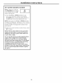
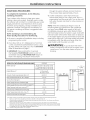
SPECIFICATIONS/DIMENSIONS
RatedCapacitg*
GNSM48F
14,300 grains with 2.8 Ibs of salt
37,700 grains with 10.4 Ibs of salt
48,000 grains with 18.1 Ibs of salt
Rated Efficiencg** 5,110 grains/lb.
@ 2.8 Ibs. of salt
Amount of High Capacitg Resin (Ibs/cu. ft) 69.2/1.55
Resin Tank Nominal Size (in.,dia. x height) 10 x 47
Service Flow Rate (gpm) 11.8
Water Suppl 9 Maximum Hardness (gpg) 120
Water Suppl 9 Maximum Clear Water h-on (ppm)*** 15
Water Pressure Limits (min.-max. psi)**** 20-125
Pressure Drop at Rated Service Flow (psig) 15
Water Temperature Limits (min.-max. °F) 40-120
Maximum Flow Rate to Drain (gpm) 2.3
i
T
38"
-,,-- 18"--,,-
9" IN-OUT
50 1A"
1
This sgstem conforms to NSF/ANS144 for the specific capacitg claims as verified and substantiated bg test data
* Testing was performed using pellet grade sodium chloride as the regenerant salt
** Effidencg rating is valid onlg at the lowest stated salt dosage and service flow rate This softener was efficiencg
rated according to NSF/ANS144
*** Extent of iron removal mag varg with conditions The capadtg to reduce clear water iron is substantiated bg
independent laboratorg test data State of Wisconsin requires additional treatment if water supplg contains greater
than 5 ppm clear water iron Use of Diamond Crgstal ®Red,Out ®or Super Iron Out ®will improve iron removal Refer
to Cleaning Iron Out of the Water Softening System section
**** Canada working pressure limits: 14-70 kg/cm _
12

About the water softener system, ge.com
Service
When the water softening system is providing
soft water, it is called "Service." During service,
hard water flows from the house main water pipe
into the water softening system. Inside the water
softening system resin tank is a bed made up of
thousands of tiny, plastic resin beads. As hard
water passes through the bed, each bead
attracts and holds the hard minerals. This is
called ion-exchanging. It is much like a magnet
attracting and holding metals. Water without
hard minerals (soft water) flows from the water
softening system and to the house pipes.
After a period of time, the resin beads become
coated with hard minerals and theg have to be
cleaned. This cleaning is called recharge.
Recharge is started at 2:00 AH (factory setting)
by the water softening system control, and
consists of five stages or cgcles. These are FILL,
BRINING, BRINE RINSE, BACKWASH and FAST
RINSE,
Automatic Hard Water Bgpass During Recharge
For emergencg needs, hard water is available
to the home during the recharge cgcles.
However, gou should avoid using HOT water
because the water heater will fill with the hard
water.
Fill
Salt dissolved in water is called brine. Brine is
needed to clean the hard minerals from resin
beads. To make the brine, water flows into the
salt storage area during the fill stage.
Brining
During brining, brine travels from the salt storage
area into the resin tank. Brine isthe cleaning
agent needed to remove hard minerals from the
resin beads. The hard minerals and brine are
discharged to the drain.
The nozzle and venturi create a suction to move
the brine, maintaining a very slow rate to get the
best resin cleaning with the least salt.
Brine Rinse
After a pre-measured amount of brine is used,
the brine valve closes. Water continues to flow in
the same path as during brining, except for the
discontinued brine flow. Hard minerals and brine
flush from the resin tank to the drain.
Backwash
During backwash, water travels up through
the resin tank at a fast flow rate, flushing
accumulated iron, dirt and sediments
from the resin bed and to the drain.
Fast Rinse
Backwash isfollowed by a fast flow of water
dawn through the resin tank. The fast flow
flushes brine from the bottom of the tank,
and packs the resin bed.
After fast rinse, the water softening system
returns to soft water service.
15

About the water softener system.
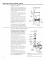
Breaking a Salt Bridge
Sometimes, a hard crust or salt bridge forms in
the salt storage area. It is usuallu caused bu high
humiditu or the wrong kind of salt. When the salt
bridges, an empt Uspace forms between the
water and salt. Then salt will not dissolve in the
water to make brine.
If the brine tank is full of salt, it is hard to tell
if Uou have a salt bridge. Salt is loose on top, but
the bridge is under it. The following is the best
wau to check for a salt bridge.
Salt should be loose all the wag to the bottom of
the tank. Take a broom handle or liketool, and
carefullu push it down into the salt, working it up
and down. If the tool strikes a hard object (be
sure it's not the bottom or sides of the tank), it's
most likelu a salt bridge. Carefullu break the
bridge with the tool. Do not pound on the walls
of the tank.
Pencil
mark
Broom -_
handle
Push tool into salt
bridge to break
/
bridge
If the wrong kind of salt made the bridge, take it
out. Then fill the tank with nugget or pellet salt
only. In humid areas, it is best to fill with less salt,
more often to prevent a salt bridge from forming.
Water level
14
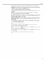
Cleaning the Nozzle and Venturi Assemblg
A clean nozzle and venturi is needed for the
water softening sgstern to work properlg. This
small unit makes the suction to move brine from
the salt storage area to the resin tank during
recharge. If it becomes plugged with sand, dirt,
etc., the water softening sustem will not work
and you will get hard water.
Toget to the nozzle and venturi, remove the
water softening system top cover Be sure the
water softening system is in service cycle (no
water pressure at nozzle and venturi). Then, while
holding the nozzle and venturi housing with one
hand, remove the cap. Lift out the screen support
and screen, then the nozzle and venturi. Wash
and rinse the parts in warm water until clean. If
needed, use a small brush to remove iron or dirt.
Also check and clean the gasket.
NOTE:Some models have a small flow plug
located in the nozzle and venturi, and/or a small
cone shaped screen in the housing. Be sure to
check and clean these parts, if your model is
so equipped.
Carefully replace all parts in the correct
order. Lightly lubricate the o-ring seal with clean
silicone grease or petroleum jelly and place in
position. Install and tighten the cap, bg hand
onlg. Do not overtighten the cap.
Cap
O-ring seal "_*0
Screen -_-_ @
support
Screen
*Flow plug _
i
Nozzle &
Venturi
_.._ Screen
Gasket -_{ _j_/i_-
*Flow -_ _,
plug
Nozzle °
Venturi
housing
IMPORTANT: Be sure small holes in the gasket ore
centered directly over the small holes in the nozzle and
venturi housing.
*Install with numbered side up, concave side down.

ge.com
Normal Operation, Timer Displag
During normal operation, the present time of day and AM or PH show in the control display
area. When the demand computer determines a regeneration is needed, RECHARGE TONIGHT
begins to flash in the display, along with the present time. RECHARGE TONIGHT flashes until
the next regeneration start time, then changes to RECHARGE NOW, which flashes until the
regeneration is oven The displag also shows the current cgcle in the regeneration process.
When the valve is in transition between cgcles, both indicators flash.
RECHARGETONIGHT
RECHARGENOW
Feature: Optional Recharge Controls
Sometimes, a manually started regeneration (recharge) may be desired or needed,
Two examples:
::Ji::You have used more water than usual (house guests, extra washing, etc,) and gou may run out
of soft water before the next regeneration.
_ You did not refill the storage tank with salt before it was all gone.
Use one of the following features to start a regeneration immediately, or at the next preset
regeneration start time.
RECHARGE NOW
Pressand hold the TOUCHor HOLDbutton until RECHARGENOW starts to flash in the control
displag area.Thewater softening sgstem beginsan immediate regeneration and,when over in
about two hours,you will havea new supply of soft waten Oncestarted, you cannot cancel this
regeneration.
RECHARGETONIGHT
Touch (donot hold)the TOUCHor HOLD button. RECHARGETONIGHTflashes in the control displag
area.A regeneration will occur at the next preset regeneration start time. If you decide to cancel
this regeneration,touch the same button once more.
Feature: Program Memorg
If electrical power to the water softening system is interrupted, the control display is blank, but the
control keeps correct time for about 72 hours. When power is restored, you have to reset the present
time only if the display is flashing. All other settings are maintained and never require resetting
unless a change is desired.
If the time is flashing after a long power outage, the water softening system continues to work as it
should to provide you with soft waten However, regenerations mag occur at the wrong time of dag
until you reset the control to the correct time of day.
15

About the water softener system.
Feature/Service: Automatic Electronic Diagnostics
The timer computer has a self-diagnostic function for the electrical sgstem (except input power and
water meter). The computer monitors the electronic components and circuits for correct operation.
Ifa malfunction occurs, an error code appears in the timer displag.
The chart on Error Codes shows the error codes that could appear and possible defects for each code.
While an error code is displaged, the TOUCH or HOLD and DATA buttons remain operable so gou can
perform the Manually Initiated Electronic Diagnostics.
ERROR CODE DISPLAYED ERR01 ERR02 ERR03 ERR04 ERR 05
POSSIBLE DEFECT _ motor inoperative _ wiring harness, or connection to switch _ timer (PWA)
position switch _ valve defect causing high torque
To remove an error code: (1)Unplug transformer
(2)Correct defect.
(3)Plug transformer in.
{4)Wait for at least 6 minutes. Theerror codewill return if the reason
for the error codewas not corrected.
REMAININGCAPACITY
FLOWRATEGPM
GALLONSTODAY
AVG.DAILY GALLONS
Feature: Other Data Displays
Ogcontinuing to press the DATA button, gou can scan through four displags of operational
information. This data appears in the bottom portion of the displag area.
REPIAINING CAPACITY -- _ This is the percentage of water softening capacitg remaining.
Immediatelg after a regeneration, 100% shows. As water is used, the percentage decreases until the
next regeneration. During regenerations, the percentage increases.
NOTE: Zero (%)shows until after the first regeneration begins, offer connecting to
electrical power
FLOW RATE,GPPI-- _ When using soft water, this displag shows the flow rate passing through
the softener (in gallons per minute). Zero shows if water is not passing through the softenen
GALLONS TODAY-- _ Each dag, beginning at midnight, the timer keeps a running count of the
total gallons of water that have passed through the softene,
AVG. DAILY GALLONS- _ The figure displaged is the average gallons of water used bg the
household each dag over the past seven dag period.
NOTE: If preferred, gou can set the timer to show the reading in liters instead of gallons. If GALLONS
TODAY or AVG. DAILY GALLONS exceeds 1999, a (xlO) indicator appears; this means gou must
multiplg the number shown bg ten.
16

ge.com
Timer/Softener, Service Checkout Procedure
Ifgou are not getting soft water, and an error code is not displaged, use the procedures below to
find the problem. First make the following visual checks:
VISUALCHECKS: IT] Isthere electrical power to the outlet the water softening sgstem transformer
_-J is plugged into?
FZ]Is there sufficient salt in the storage tank?
E]ls the plumbing bgpass valve directing water for soft water service?
F_-]ls the valve drain hose open to the drain, not more than 8' above the
/
softener, and unobstructed? Ifhose is above 8, see page 8, section 5.
Ifgou do not find a problem with the visual checks, continue below.
TIMER
DISPLAY
BLANK.
TIMERSHOWS
WRONG TIME AND
DAY,AND/OR IS
FLASHING.
• REPAIRAS
Checkelectrlcal I [NOPOWER 1 I ......
power to control
(outlet,transformer, I-_L_JPOWER OKI . i
power cable, all |_1 .......... I'-_" TIMER
connections). | I DEFECTIVE
fl Electrical _ Investigate reasonfor
power
was
off.Resetthe correct
power oss.
| time of dag.
Do manual
diagnostics
to verifg
proper
function.
TIMER DISPLAYSHOWS
CORRECTTIME AND DAY
AND ISSTEADY.
Domanual
diagnostics.
17

About the water softener system.
°d'-; -
LaSr_GE
WArS_MAt_GE_T SY_T_
Switch Turbine
count
Valve Minutes of cycle
position rernaining
Id "i,C id
rlt_
wArERMAt_G_ENTSrSr_
........i-I r"li'l
""- Ij IjIj
Service: Manually Initiated Electronic Diagnostics
F_]To enter diagnostics, press and hold the DATAbutton until the display appears as shown.
NOTE:Ifthe softener is in the middle of a regeneration, top part of the display shows the cycle
of regeneration and minutes of the cycle remaining. Iftwo cycle names are flashing, the valve
isin transition between the cycles.
A Thethree digits under WATERMANAGEMENTSYSTEMindicate water meter operation
asfollows:
!i_:000 (steady)= softwater not inuse_.noflow through the meteE
--OPENA NEARBYSOFTWATERFAUCET--
!;_ 000 to 140 (continual)= repeats display for each gallon ofwater passing through the
meteE
_, _ Motor
! _ Sensor
I_ housing
I _ _ Turbine
-_1_ ------_Turbine
Valve _ support &
outlet _ shaft
If you don't get a reading in the display, with faucet open,pull the sensorfrom the valveoutlet
port. Passa small magnet back and forth in front of the sensoEYoushould get a reading in the
display.If you get a reading,shut off water supply,unhook the in and out plumbing and check
the turbine for binding.
B Thisdisplay segment (_x.i), in the following chart, indicatesan open POSITIONswitch.
Usethe TOUCHor HOLDbutton to manually advance the valveinto each cycle and check
correctswitch operation.
CORRECTSWITCH
DISPLAYS VALVECYCLE STATUS
Valve in service, fill, brining, backwash
or fast rinse position,
Valve rotating from one position to anotheE
I
I
WAT£eMAN4_NTS_rEM
--I
Clb,o
[_ Pressthe DATAbutton again,Thisdiagnostic display shows the total number of recharges(top)
since the timer was connected to electrical powe_
The number of days sincethe timer was connected to electrical power is shown in the bottom
part of the display. If over 1999 days, a (×10)indicator shows,meaning you must multiply the
number shown by 10.
[_ PressDATAonce again to return the presenttime to the display.
18

ge.com
Service: Manually Advance Regeneration Check
Thischeckverifies proper operation of the valve motor,brine tank fill, brine draw, regeneration
flow rates and other controller functions. First,makethe initial checksand the manuallg initiated
electronic diagnostics.
NOTE:The face plate displag must show a steady time (notflashing).
r_] Pressthe TOUCHor HOLDbutton and hold for three seconds.RECHARGENOW begins
to flash asthe water softening sgstem enters the fill cgcle of regeneration. Removethe
brinewell cover and,using a flashlight, observe fillwater entering the brine tank.
If water does not enter the tank, lookfor an obstructed nozzle,venturi,fill flow plug,brine
tubing or brine valve riserpipe.
r_l After observing fill,pressthe TOUCHor HOLD button to movethe water softening sgstem into
brining.A slow flow of water to the drain will begin.Verifg brine draw from the brine tank bg
shining a flashlight intothe brinewell and observinga noticeable drop inthe liquidlevel.
NOTE:Be surea salt bridge isnot preventing salt contact with wate_
If the water softening system doesnot draw brine,check:
!i_nozzleand/or venturi dirtg or defective.
ij_:,nozzleand venturi not seated properlg on gasket.
iJi:,restricted drain (checkdrain fitting and hose).
ij_:,defective nozzleand venturi seal.
_ other inner valve defect (rotorseal,rotor & disc,wave washer,etc.).
NOTE:If water sgstem pressure islow,an elevateddrain hose mag cause back pressure,stopping
brine draw.
r_ Again,pressthe TOUCHor HOLD button to move the softener into backwash. Lookfor a fast
flow of water from the drain hose.
A slow flow indicates a plugged top distributor, backwash flow plug or drain hose.
r_ PressTOUCHor HOLDto move thewater softening sgstem into fast rinse.Again lookfor afast
drain flow.Allowthe water softeningsgstem to rinsefor a few minutes to flush out ang brine
that mag remain in the resintank from the brining cgcle test.
r_To return the water softening sgstem to service,pressTOUCHor HOLD.
19

About the water softener system.
SET
Service: Regeneration and Heavy Duty Backwash
NOTE:Each of the following functions has a factorg-set default value. The defaults are: Regeneration start time
-2:00AM; Ha×imum dags between regenerations-O (displag shows dY-); Efficiencgmode-ON; Heavg dutg
backwash -OFF. The defaults are suitable for most installations. However, depending on water supplg qualitg,
household peak water use hours, etc., adjustment is available to meet specific needs. To make a change, read
and do the following.
Regeneration (Start) Time: Atthe 2:00 AH regeneration start time, the water softening sgstem begins
regeneration at that time, ending at about 4:00 AH.This is a good time in most households because water is not
in use(seeAutomatic Hard Water BypassDuringRegenerationsection).If a different time would bebetterfor gour
needs,do stepsZ,2,3,5,7,9 and 11 belowto changethe starting hour.
Maximum Days Between Regeneration: Thedefault setting (dY-)allows the timer to control regeneration
frequencg basedon water usage readingsfrom the water meteEIt providesthe most economical operation.
You can set a maximum time (indabs)between regenerations.Forexample, no more than three dabs will pass
without a regeneration occurring if gou set dY3 in the displag.A ! to 7 dab setting isavailable.To make a
change from the default setting, do steps Z,3,4,5,7,9 and !1 below.
Efficiency Mode: Whenthis feature isON,the unit will operate at salt efficienciesof 4000 grainsof harness per
pound of salt or higheE(Hag recharge more often usingsmaller salt dosage and lesswater).Whenthis isON,
the efficiencg icon_ will show in the lower right hand comer of the displag.To make a change for the
default setting, do steps !, 3,5,6,7,9 and !! below.
Heavy Duty Backwash: When set to ON,the backwash cgcle of regeneration will be 10 minutes long instead
of the normal seven minute length.Thisisbeneficial on some water supplies high in iron or sediment content.
Toconserve water,on clean supplies,be surethe default setting OFFshows.Tochange this setting, do steps !,
3,5,7,8,9 and !1 below.
Auto Regeneration When Capacity is Lo_. Thesoftener will regenerate at the regeneration time onlg.
Although the control hasa look-forward feature which anticipates normal demand,an unusuallg high usage
mag result in a lossof softening capacitg. Turning the feature ONwill cause the softenerto go into a
regeneration cgcle when 97% ofthe softening capacitg has been used.Tochange settings,do steps1,3,5,7,9,
10 and 11 below.
[] Beginningfrom the present time displag, pressand hold in the SETbutton until _ beginsto flash.
[_ Pressthe UPor DOWN button to displogthe desiredstart time.The UPbutton movesthe time ahead;the
DOWN button movesthe time backward.
[] Pressthe SETbutton again,and _ flashes.
[_To set a maximum time {indabs)between regenerations, pressthe UPor DOWN button.
[] Pressthe SETbutton again and the ONflashesand the efficiencg mode icon
shows in the lower right hand corner of the screen.
[_Use the UPor DOWN arrows to toggle the efficiencg mode either ONor OFF.
[] Pressthe SETbutton to displag _.
[_Use the UPbutton to change the displagto ON to increase the backwash time, if desired.
[] Pressthe SETbutton _ and _ alternatelg flashes.
[_Use the UPbutton to turn Auto Regeneration cgcle to ON.
[_ Pressthe SETbutton a final time to return to present time of daB.
20
Page is loading ...
Page is loading ...
Page is loading ...
Page is loading ...
Page is loading ...
Page is loading ...
Page is loading ...
Page is loading ...
Page is loading ...
Page is loading ...
Page is loading ...
Page is loading ...
-
 1
1
-
 2
2
-
 3
3
-
 4
4
-
 5
5
-
 6
6
-
 7
7
-
 8
8
-
 9
9
-
 10
10
-
 11
11
-
 12
12
-
 13
13
-
 14
14
-
 15
15
-
 16
16
-
 17
17
-
 18
18
-
 19
19
-
 20
20
-
 21
21
-
 22
22
-
 23
23
-
 24
24
-
 25
25
-
 26
26
-
 27
27
-
 28
28
-
 29
29
-
 30
30
-
 31
31
-
 32
32


GE GNSM48F00 Owner's manual
- Category
- Water dispensers
- Type
- Owner's manual
Ask a question and I''ll find the answer in the document
Finding information in a document is now easier with AI
Related papers
Other documents
-
 GE Monogram GXSF30H User manual
-
 Express Water GTS11 User manual
-
Jones Stephens D59130 Installation guide
-
Aerus HF 300 Operating instructions
-
ISPRING UVT11A Operating instructions
-
 T & S Brass & Bronze Works B-1413 Datasheet
-
Pentair Whole House Water Softening System Owner's manual
-
Hellenbrand WM1-96M Owner's manual
-
SureSoft 419022 User manual
-
Tier1 TIER1-WH-HD-IRN-MG-1054 Installation guide


