Page is loading ...

DATAR AD IOPARAGON4
PD+
DIGITALBAS ESTAT IO N
USERMANUAL
PN001‐P4PD‐000REV1
RELEASEDDECEMBER2010


RevisionHistory
Revision0 2010September
InitialRelease
Revision1 2010December
UpdatestoSection2.5,3.4.2.3.4,4.0and5.0

TableofContents
1 PRODUCTOVERVIEW..............................................................................................................................................1
1.1 I
NTENDEDAUDIENCE.......................................................................................................................................................1
1.2 G
ENERALDESCRIPTION.....................................................................................................................................................1
1.2.1 NetworkSpeedsandModulation..........................................................................................................................2
1.3 T
ECHNICALSUPPORT........................................................................................................................................................2
1.4 P
RODUCTWARRANTY......................................................................................................................................................2
1.5 R
EPLACEMENTPARTS.......................................................................................................................................................3
1.6 F
ACTORYREPAIR.............................................................................................................................................................3
1.7 P
ACKAGING....................................................................................................................................................................4
1.8 M
ODULEVIEWS..............................................................................................................................................................5
2 INSTALLATION.........................................................................................................................................................8
2.1 O
VERVIEW.....................................................................................................................................................................8
2.2 L
OCATION......................................................................................................................................................................8
2.3 E
LECTRICAL....................................................................................................................................................................8
2.3.1 PowerSupplyConnections..................................................................................................................................11
2.3.2 PowersupplyFuseReplacement.........................................................................................................................12
2.3.3 PowerAmplifierConnections..............................................................................................................................14
2.3.4 RadioAssemblyConnections...............................................................................................................................14
2.3.5 AntennaCablingandConnection........................................................................................................................15
2.4 C
OMPLETINGTHEPHYSICALINSTALLATION.........................................................................................................................15
2.5 C
HECKINGNORMALOPERATION......................................................................................................................................16
3 OPERATINGDESCRIPTION......................................................................................................................................17
3.1 P
OWERSUPPLY.............................................................................................................................................................17
3.2 P
OWERAMPLIFIER........................................................................................................................................................17
3.3 R
ADIOASSEMBLY..........................................................................................................................................................17
3.3.1 SDRDiversityReceivermodule............................................................................................................................18
3.3.2 SDRExcitermodule..............................................................................................................................................19
3.3.3 Speakerpanel......................................................................................................................................................19
3.4 BDLC
PD+
.....................................................................................................................................................................20
3.4.1 FrontSwitch(Reset).............................................................................................................................................20
3.4.2 FrontSwitch(Multi‐functionPF1).......................................................................................................................20
3.4.3 BDLC
PD+
Rearpanel..............................................................................................................................................24
4 MAINTENANCE&TESTING.....................................................................................................................................26
4.1 E
QUIPMENTREQUIRED...................................................................................................................................................26
4.2 M
AINTENANCEPROGRAMS.............................................................................................................................................26
4.2.1 WinRIS.exe...........................................................................................................................................................27
4.2.2 4PDPLUS_SDR_Tx_Freq.exe.................................................................................................................................28
4.2.3 4PDPLUS_SDR_Rx_Freq.exe.................................................................................................................................29
4.3 P
OSTINSTALLATIONCHECKS............................................................................................................................................30
4.4 A
NNUAL&PERIODICTESTING..........................................................................................................................................31
4.4.2 RFDataLinkTest..................................................................................................................................................34
5 SPECIFICATIONS....................................................................................................................................................35
APPENDIXA–PRODUCTWARRANTY..............................................................................................................................37
APPENDIXB–DEFINITIONS............................................................................................................................................38

F
IGURE1‐RADIOASSEMBLY(FRONTVIEW)..........................................................................................................................................5
FIGURE2‐RADIOASSEMBLY(REARVIEW)............................................................................................................................................5
FIGURE3‐POWERAMPLIFIER(FRONTVIEW)........................................................................................................................................6
FIGURE4‐POWERAMPLIFIER(REARVIEW)..........................................................................................................................................6
FIGURE5‐BDLC
PD+
(FRONTVIEW).....................................................................................................................................................6
FIGURE6‐BDLC
PD+
(REARVIEW).......................................................................................................................................................6
FIGURE7‐REDUNDANTPOWERSUPPLY(FRONTVIEW)..........................................................................................................................7
FIGURE8‐REDUNDANTPOWERSUPPLY(REARVIEW)............................................................................................................................7
FIGURE9‐SIMPLEAC‐TO‐DCPOWERCONFIGURATIONBLOCKDIAGRAM..................................................................................................8
FIGURE10‐STANDARDCONNECTIONSUSINGICT22012‐70NPOWERSUPPLY.........................................................................................9
FIGURE11‐STANDARDCONNECTIONSUSINGCUSTOMERPROVIDEDPOWERSUPPLY.................................................................................10
FIGURE12‐POWERSUPPLYSCREWREMOVALDETAIL..........................................................................................................................12
FIGURE13‐POWERSUPPLYMODULEASSEMBLY.................................................................................................................................12
FIGURE14‐MODULE2,MODULE4FUSEDETAIL................................................................................................................................13
FIGURE15‐POWERSUPPLYBACKPLANEASSEMBLYFUSE......................................................................................................................13
FIGURE16‐RADIOASSEMBLYBACKPLANE..........................................................................................................................................14
FIGURE17‐ATOBLADEFUSE..........................................................................................................................................................15
FIGURE18‐SDRUHFRECEIVERMODULE.........................................................................................................................................18
FIGURE19‐SDREXCITERMODULE...................................................................................................................................................19
FIGURE20‐SPEAKERMODULE.........................................................................................................................................................19
FIGURE21‐BDLC
PD+
.....................................................................................................................................................................20
FIGURE22‐BDLC
PD+
FRONTPANELDETAILS......................................................................................................................................23
T
ABLE1‐ON‐AIRDATASPEEDSANDMODULATIONTYPES.........................................................................................................................2
TABLE2‐ICT22012‐70NLEDMODULESTATUSDISPLAY...................................................................................................................17
TABLE3‐POWERAMPLIFIERINDICATORS...........................................................................................................................................17
TABLE4‐SDRDIVERSITYRECEIVERMODULELEDS..............................................................................................................................18
TABLE5–SDREXCITERMODULELEDS.............................................................................................................................................19
TABLE6‐BINARYTXMODESELECTIONLEDINDICATIONS.....................................................................................................................21
TABLE7‐DGMSKTESTTRANSMISSIONS...........................................................................................................................................21
TABLE8‐TESTTRANSMISSIONSXRC4FSK/XRC8FSK...........................................................................................................................21
TABLE9‐RS‐232LEDFUNCTIONSELECTIONSEQUENCE......................................................................................................................22
TABLE10‐RS‐232SIGNALLEVELS....................................................................................................................................................25
TABLE11‐DTEPORT9‐PINFUNCTIONS............................................................................................................................................25
TABLE12‐POSTINSTALLATIONCHECKLIST..........................................................................................................................................30
TABLE13‐BACKPLANETESTPOINTS..................................................................................................................................................31
TABLE14‐MAINTENANCECHECKLIST(GENERAL)................................................................................................................................31
TABLE15‐CARRIERDEVIATIONSFORTONEORDATAMODULATION........................................................................................................33
TABLE16–EMISSIONDESIGNATORS..................................................................................................................................................35

ImportantNotice
Becauseofthenatureofwirelesscommunication,transmissionandreceptionofdatacanneverbeguaranteed.Datamay
bedelayed,corrupted(i.e.,haveerrors),orbetotallylost.Significantdelaysorlossesofdataarerarewhenwirelessdevices
areusedinanormalmannerwithawell‐constructednetwork.This
productshouldnotbeusedinsituationswherefailure
totransmitorreceivedatacouldresultindamageofanykindtotheuseroranyotherparty,includingbutnotlimitedto
personalinjury,death,orlossofproperty.CalAmpacceptsnoresponsibilityfordamagesofanykindresulting
fromdelays
orerrorsindatatransmittedorreceived,orforthefailuretotransmitorreceivesuchdata.
CopyrightNotice
©2010CalAmp.Allrightsreserved.ProductsofferedmaycontainsoftwareproprietarytoCalAmp.Theofferofsupplyof
theseproductsandservicesdoesnotincludeorinferanytransferofownership.Nopartofthedocumentationor
informationsuppliedmaybedivulgedtoanythirdpartywithouttheexpresswritten
consentofCalAmp.CalAmpreserves
therighttoupdateitsproducts,software,ordocumentationwithoutobligationtonotifyanyindividualorentity.Product
updatesmayresultindifferencesbetweentheinformationprovidedinthismanualandtheproductshipped.
Dataradio,VIS,andParallelDecodeareregisteredtrademarks.Paragon,Paragon
PD
,andParagon
PD+
aretrademarksof
CalAmp.
UserManualStatement
Everyeffortistakentoprovideaccurate,timelyproductinformationinthisusermanual.Productupdatesmayresultin
differencesbetweentheinformationprovidedhereinandtheproductshipped.Theinformationinthisdocumentissubject
tochangewithoutnotice.
AboutCalAmp
CalAmpisaleadingproviderofwirelessequipment,engineeringservicesandsoftwarethatenableanytime/anywhere
accesstocriticalinformation,dataandentertainmentcontent.Withcomprehensivecapabilitiesrangingfromproduct
designanddevelopmentthroughvolumeproduction,CalAmpdeliverscost‐effectivehighqualitysolutionstoabroadarray
ofcustomersandendmarkets.
CalAmpistheleadingsupplierofDirectBroadcastSatellite(DBS)outdoorcustomerpremise
equipmenttotheU.S.satellitetelevisionmarket.TheCompanyalsoprovideswirelessconnectivitysolutionsforthe
telemetryandassettrackingmarkets,publicsafetycommunications,thehealthcareindustry,anddigitalmultimedia
deliveryapplications.
Foradditionalinformation,visitwww.calamp.com
.

Page|1
1 PRODUCTOVERVIEW
Thisdocumentprovidesinformationrequiredforthesettingup,operation,testingandtrouble‐shootingoftheParagon4
PD+
BaseStation.
1.1 INTENDEDAUDIENCE
Thisdocumentisintendedforengineering,installation,andmaintenancepersonnel.
1.2 GENERALDESCRIPTION
Paragon4
PD+
isafactory‐integratedindustrial‐gradedatabasestationusedinmobilenetworks.Designedspecificallytofit
theneedsofvehicularapplications,itfeaturesdualreceiversforaddeddatadecodesensitivityinmulti‐pathandfading
environments.WhenusedwithGemini
PD+
mobiles,thesystemdelivershigh‐speeddataperformanceandunmatched
effectivethroughput.
AllParagon4
PD+
modelsaresuppliedinarack‐mountconfigurationthatincludes:
(1)Full‐duplexRadioAssemblywithSDR(SoftwareDefinedRadio)Di ve rsityReceiver,SDRExciterandSpeakerPanel
(1)PowerAmplifier
(1)High‐speedBaseStationData LinkController(BDLC
PD+
)
Additionalcomponents/requirementsinclude:
Duplexerandback u ppoweruni ts arecustomfurnisheditems
Wirelinemodem(s)areoptionalitems
LaptopPCanditsapplicationsoftwareare user‐supplieditems
ProductFeatures:
ParallelDecode®featuringdualreceiversforaddeddecodesensitivityinmulti‐pathandfadingenvironments
SophisticatedDSP‐basedmodemdesignprovidesaddedsystemperformance,fewerretriesandmoreeffective
throughput
Fullduplexoperation
Poweroutputof50‐100WforUHFand35‐70Wfor800MHz
Upto43.2kb/s
12.5,NPSPACand25kHzchannelspacing
Supportshigh‐efficiency
DataradioDBAover‐the‐airprotocol
Out‐of‐bandsignalingenablestransmissionofGPSreportswithnoeffectonsystemperformance
Four(4)timesmoreDSPmemorythanpreviousmodelstohandlehigherratemodulationtypes
Flashprogrammablefirmware
Modulardesign
Factory‐configuredbasedoncustomer’s
networksystemrequirements

Page|2
1.2.1 NETWORKSPEEDSANDMODULATION
TheParagon4
PD+
supportsdataspeedsontheRFnetworkofupto43.2kb/sbymodulatingtheRFcarrier.Lowerspeedsare
producedbya2‐levelmodulation(DGMSK),middleandhigherspeedsby4‐level(xRC4FSK)and8‐level(xRC8FSK)
modulations.Somenetworkspeedshavemorethanonechoiceofmodulation.
SystemEngineeringselectsandinformsthe
customerofthenetworkspeedandmodulationthatbestmeetsthecustomer'srequirementsofthroughput,rangeand
robustness.
Table1‐On‐airdataspeedsandmodulationtypes
ModulationType
1
12.5kHzChannelSpacing NPSPACChannelSpacing 25kHzChannelSpacing
DGMSK 9.6kb/s 19.2kb/s
8.0kb/s 9.6kb/s
xRC4FSK 16kb/s 16kb/s 32kb/s
2
14.4kb/s 25.6kb/s
19.2kb/s
xRC8FSK
2
21.6kb/s 24kb/s 43.2kb/s
1.3 TECHNICALSUPPORT
TheTechnicalSupportdepartmentprovidescustomerassistanceontechnicalproblemsandservesasaninterfacewith
factoryrepairfacilities.StandardsupportisavailableMonday–Friday9:00AMto5:00PMEST.Extendedsupportplansare
available.
CalAmpWirelessNetworks
299JohnsonAvenue,Ste110
Waseca,MN56093
Tel(507)
833‐8816x6701orTollFree(800)992‐7774x6701
Fax(507)833‐6748
Email[email protected]
1.4 PRODUCTWARRANTY
ItisourguaranteethateveryParagon4
PD+
willbefreefromphysicaldefectsinmaterialandworkmanshipforONEYEAR
fromthedateofpurchasewhenusedwithinthelimitssetforthinSection5:Specifications.Thestandardmanufacturer's
warrantystatementisavailableinAPPENDIXA–PRODUCTWARRANTY.
Extendedwarrantyplansareavailable.ContactyourCalAmprepresentative
foroptions.
1
Networksmustusecommonmodulation,bitandbaudrates.
2
AvailablewithParagon
PD+
andGemini
PD+
productsonly

Page|3
1.5 REPLACEMENTPARTS
Thisproductisgenerallynotfield‐serviceable,exceptbythereplacementofindividualradiomodules.Specialized
equipmentandtrainingisrequiredtorepairlogic,modemboards,andradiomodules.
ContactTechnicalSupportforserviceinformationbeforereturningequipment.Asupportrepresentativemaysuggesta
solutioneliminatingtheneedtoreturnequipment.
1.6 FACTORYREPAIR
Whenreturningequipmentforrepair,youmustrequestanRMA(ReturnedMaterialAuthorization)number.Contactour
CustomerServiceDepartmentat(800)992‐7774toobtainanRMAnumber.Thesupportrepresentativemayaskyou
severalquestionstoclearlyidentifytheproblem.Pleasegivetherepresentativethenameofacontactperson
whois
familiarwiththeproblemshouldaquestionariseduringservicingoftheunit.
BESURETOHAVETHEEQUIPMENTMODEL,SERIALNUMBER,ANDBILLING&SHIPPINGADDRESSESAVAILABLEWHEN
CALLING.YoumayalsorequestanRMAnumberonlineatwww.calamp.com
.
Customersareresponsibleforshippingchargesforreturnedunits.Unitsinwarrantywillberepairedfreeofchargeunless
thereisevidenceofabuseordamagebeyondthetermsofthewarranty.Unitsoutofwarrantywillbesubjecttoservice
charges.InformationaboutthesechargesisavailablefromTechnical
Support.

Page|4
1.7 PACKAGING
EachParagon4
PD+
ispackagedwiththefollowing:
(A1)RadioAssembly
(C5)BDLC
PD+
toRadioAssemblyBackplanePowerCable
(A2)PowerAmplifier
(C1)PowerAmplifierDCPowerCable*
(A4)RedundantPowerSupplywithACPowerCable*
(C2)PowerAmplifierFusedDCPowerCable
(C6)BDLC
PD+
toRadioAssemblyBackplaneDataCable
(C3)RadioAssemblyBackplaneDCPowerCable
(A3)BDLC
PD+
(C4)TypeNRightAngletoTypeNStraightRG223/UCable
ParagonP4
PD+
StartUpDiscwithUserManualandMaintenance
&
TestingPrograms
*PowerSupplyisincludedonlyiforderedasanoption.Iforderedwithpowersupply,CableC1isincludedtoreplace
CableC2.

Page|5
Frequently,componentsarestagedbySystemEngineeringandarepartiallyassembledpriortodelivery.Finalinstallationis
doneatthecustomer’slocation.
Cabinetrymaybesuppliedinoneof severalcustomrack‐mountconfigurationsthatmayals oincludefan,backhaulmodems,
duplexer/filters/combiners,andancillar yequipment.
Ifdamage
hasoccurredtotheequipmentduringshipment,fileacl ai mwiththe carrierimmediatel y.
1.8 MODULEVIEWS
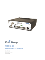
Figure1‐RadioAssembly(FrontView)
Figure2‐RadioAssembly(RearView)

Page|6
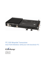
Figure3‐PowerAmplifier(FrontView)
Figure4‐PowerAmplifier(RearView)
Figure5‐BDLC
PD+
(FrontView)
Figure6‐BDLC
PD+
(RearView)

Page|7
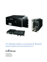
Figure7‐RedundantPowerSupply(FrontView)
Figure8‐RedundantPowerSupply(RearView)

Page|8
2 INSTALLATION
2.1 OVERVIEW
Thecabinetandrack‐mounthousingParagon4
PD+
isgenerallyinstalledinashelteredfacility.Occasionallylocatedadjacent
tothenervecenteroftheuser’snetwork,itismoreoftenlocatedneartowersitesoratremotelocationswhereitoperates
unattended.
Furnishingsneededincludepower,cabling,andinstallationofantenna,landlineormicrowavemodem,andhostPC
or
portablecomputer.Detailsoftheseareoutsidethescopeofthismanual.ThismanualonlycoverstheRadioAssemblyand
theBDLC
PD+
componentthatincludesthemodem.
2.2 LOCATION
BesuretoplacetheParagon4
PD+
equipmentinsuchawaythat:
TheLEDscanbeseen(asanaidintroubleshooting).
Accesstotheantennaconne ct o r s andto thebackconnectorsispossiblewithoutremovingtheunit.
Sufficientairmayfl owaroundtheunittoprovid eadequatecooling.
2.3 ELECTRICAL
Standard120/240VACelectricalpowercapableofprovidingatleast13A(120V)or9.3A(240V)isrequiredtopowerthe
basestationandancillaryequipment.
Thestandardconfigurationforsupplyingtherequired+13.8VDCtotheParagon4basestationandthePowerAmplifieris
shownbelow.TheRadioAssemblyandthe
poweramplifierreceive13.8VDCpowerinputsfromthe120VACpowersupply
module.Illustrationsanddiagramsprovidedreferencetheoptionallysuppliedrack‐mountedpowersupply(ModelICT
22012‐70N).
Figure9‐SimpleAC‐to‐DCPowerConfigurationBlockDiagram

Page|9
Figure10‐StandardConnectionsUsingICT22012‐70NPowerSupply

Page|10
Figure11‐StandardConnectionsUsingCustomerProvidedPowerSupply

Page|11
2.3.1 POWERSUPPLYCONNECTIONS
ModelnumberICT22012‐70Nisarack‐mountedpowersupplyunitprovidedbyCalAmpasanoption.Itconsistsofa
backplaneandtwomodules.Eachmoduleprovides450WattsofcontinuousDCpoweroutputat13.8V/32.6A.Thesystem
isdesignedwithactivesharingtechnologytodistributetheloadcurrent
amongthemodules.Eachmoduleisequippedwith
ahighpowerSchottkyOR‐ingdiodefortrueredundancy.Ifamodulefailureoccurs,theothermodulewillcontinueto
supplypower.
Themoduleisprotectedinseveralways:
FuseagainstovercurrentontheACinput.
CurrentLimitandFoldback–Preventstheloadfromdrawingcurrentabovethemaximumallowedvalue.
Suddenenergysurgesoneachmodule–Thermistoragainstinrushcurrent.
Priortopoweringup,ensurethatbothvoltageselectionswitches(locatedontheback)aresettothepropervoltagefor
youroperation.Availablesettings
are120or220volts.ThePowerSupplymetalenclosureisinternallyconnectedtoearth
groundviaitsindividual,rear‐connected,120VAC(NEMA5‐15pplugtoIEC60320‐C19receptacle)powercord.Therefore,
thesystemmustbeoperatedfromanoutletwithapropergroundingconnection.Impropergrounding
betweenpower
supplycaseandrackframemayresultinharmfulvoltagepotentialsand/ormiscellaneouspowersupplyswitchingnoise
problemsinbothreceiversandtransmitter.
Caution:
Highcurrentleakage,useonlythecordsuppliedwiththisequipmentforpower.
Ifaccessingmodules,poweratboththeswitchandthe
ACinletmustbedisconnectedtoensureoperatorsafety.
Itisimportantthatthesideventilationholesareunobstructedatalltimes.Donotoperatethisunitina
completelyenclosedcabinet.

Page|12
2.3.2 POWERSUPPLYFUSE REPLACEMENT
ToaccessthePowerSupplyfuses,theunitcovermustberemoved.Besurethatallpowertotheunitisremoved.Asshown
inFigure12,removethethreetopscrewsandfoursidescrewswithwashersandthenslidethetopcoveroff.
Figure12‐PowerSupplyScrewRemoval
Detail
Thereisone250V10Afuseforeachmoduleboardassembly(showninFigure13andFigure14)andone250V1Afuseon
thebackplaneboardassembly(showninFigure15)forthefans.Locateeachfuseandreplaceasneeded.Toprotectagainst
fireorelectricalshock,
replacewithonlythesametypeandratingsoffuse.Onlyhandtightentheeightscrewswhen
replacingthecover.
Figure13‐PowerSupplyModuleAssembly

Page|13
Figure14‐Module2,Module4FuseDetail
Figure15‐PowerSupplyBackplaneAssemblyFuse

Page|14
2.3.3 POWERAMPLIFIERCONNECTIONS
ThePowerAmplifierismaintenancefreewithonlyLEDindicatorspresentonthefrontpanelandoneadjustmentlocated
ontheunderside.TheDCpowerterminalblock,RFInandRFOutarelocatedonthebacksideofthemodule.
Inastandardconfiguration,thePowerAmplifierreceivesits+13.8
VDCpowerfromthePowerSupplythrougha10AWGDC
powercable.Thereisnoin‐linefusebetweenthepowersupplyandpoweramplifier.Allshort‐circuitandfoldback
protectionisdonebythePowerSupply.
Forthe800MHzmodel,thepoweroutputisnormallysetto
70W(orlowerdependingontheworkorder)andfortheUHF
model,itissetto100W(orlowerdependingontheworkorder)attimeofmanufactureorviaRMA.However,toallowfor
fieldadjustmentoftheoutputpowertomeettheERPgrantedbythetransmissionsite
license,apotentiometeris
accessibleviaasmallroundopeningontheundersideofthepoweramplifier.Adjustusingasmalltuningscrewdriver.
CalAmpdoesnotrecommendadjustingbelow35Wforthe800MHzmodeland50WfortheUHFmodel.
AsperIndustryCanadaRadioStandardSpecification#131,paragraph
5.3:
“[…]Themanufacturer'sratedoutputpowerandpowertoleranceofthisequipmentisforsinglecarrier
operationinthespecifiedfrequencyrange.Itshouldnotbeusedformultiplecarrieroperationsoroutside
itsspecifiedrange[…]”
2.3.4 RADIOASSEMBLYCONNECTIONS
TheBDLC
PD+
andRadioAssembly(DiversitySDRRx,SDRExciterandSpeakermodules)receivetheir+13.8VDCpowerviathe
backplanePCB.A12AWGDCpowercableprovidespowertothebackplanePCBattheheavydutypowerconnectorJ20.
Thebasestationrequiresasecuregroundconnection.Agrounding8‐32
threadedthrough‐holepemstudfittedwitha8‐32
screw,lockwasherandnutisprovidedonthebottom‐rearofthechassis,behindthespeakerpanel.
Installa3 ‐4ft10AWGgroundingwire,crimpedonbothsideswithterminalrings.Placeonesideoverthe8‐32
screw
onthenon‐exposedchassissideandfirmlytightenwiththelockwasherandnut.
Placetheothersideontherearsidethepowersupplymetalcase,nearthe25‐pinconnector.Usea½in4‐40
screwwithlockwashertosecuretheterminalringto
themetalcase.
Ifa–DCrail(0V)isinstalledaspartofthesystem,thegroundingleadmayalternativelybefittedtotherail
terminal.
Figure16‐RadioAssemblyBackplane
/