
PLL WIRELESS SYSTEMS INSTRUCTION MANUAL
UHF
59506-127

Thank you for choosing the JTS wireless system. In order to obtain the best efficiency from
the system, you are recommended to take few minutes to read this instruction manual carefully.
TABLE CONTENTS
1. Important Cautions ................................................................................ 1
2. Features................................................................................................... 1
3. Specification............................................................................................ 2
3-1 Receiver.............................................................................................. 2
3-2 Transmitter......................................................................................... 2
3-3 Condenser Microphone...................................................................... 3
4. Parts Identification & Accessories......................................................... 4
4-1 Receiver.............................................................................................. 4
4-2 Handheld Transmitter........................................................................ 4
4-3 Body-pack Transmitter...................................................................... 5
4-4 Condenser Microphone...................................................................... 5-6
4-5 Optional accessories...........................................................................6
5. Preparing procedures & basic operation ............................................... 7-12
6. Preparing procedures ............................................................................. 13-14
7. Preparing procedures of condenser microphone & accessories........... 15-16
8. Recommendations................................................................................... 16
1. Important Cautions
1-1 Always make all connections before plugging the unit into an AC power outlet.
1-2 Do not leave the devices in a place neither with high temperature nor high humidity.
1-3 Always do not handle the power cord with wet hands !
1-4 Keep the devices away from fire and heat sources.
2. Features
* Operated in UHF band where there is less RF interference than the VHF band.
* Due to the PLL synthesized technology, the system can offer up to 961 selectable
frequencies for choosing simultaneously.
* The true diversity reception with 2 independent RF receivers ensure the stable
transmission and reception.
* Adjustable Pilot tone squelch control can effectively reduce the noise.
* Equipped with S.A.W. filter benefits the interference-resistant.
* Tuned antennas can benefit the stable RF reception.
* Built-in Noise Squelch circuity & Mute function are available to restrain the
interference for signals.
* Compact half-rack receiver design is considerable for the space saving.
* Rugged metal housing can pass through the difficult environment.
* Equipped with balanced XLR and unbalanced output allow great convenience.
* Anti-interference design is available to work with every computer device.
~1~

~3~
~2~
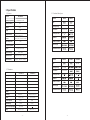
3-3 Condenser Microphone
Model No.
Type
Frequency Range
Polar Pattern
sensitivty(at 1 kHz)
Impedance
Max SPL for 1%THD
Connector type
Standard Accessories
CM-501
-60dB 3dB
CM-201
Model No.
Type
Frequency Range
Polar Pattern
sensitivty(at 1 kHz)
Impedance
Max SPL for 1%THD
Connector type
Standard Accessories
CX-508W
Wind Mic.
-67dB 30%
220 30%
CX-504
-60dB 30%
60~15.000Hz
Omni directional
CM-204
60Hz~15.000Hz
Omni directional
100Hz~15.000Hz
3. Specification
3-1 Receiver
Model No.
Frequency Preparation
Frequency Stability
S/N Ratio
Display
Display Contents
Controls
Audio Output Level
AF Output Impedance
Squelch
Operation Voltage
Output Connector
Dimension(m/m)
US-1000D-TH
PLL Synthesized Control
.005%
100dB
LCD
Frequency , Antenna A/B, Mute Status,
RF/AF Level, Battery level
Power On/Off, Frequency Up/Down,
Frequency Scan , Audio Level Volume
-12dB
600
Pilot Tone & Noise Mute
12VDC, 600mA
XLR Balanced/Unbalanced .3mm plug
211mm(W) * 40mm(H) * 167mm(D)
3-2 Transmitter
PLL Synthesized Control
494 ~ 870MHz
10mW
.005%
48KHz
102dB
Frequency, Battery level.
Power On/Off, Frequency,
AF level control
-60 dBc
+110 dB
UM3,AA.1.5V * 2
PT-990B-TH(mi)
Model No.
Frequency Preparation
Carrier Frequency Range
RF Output
Stability
Frequency Deviation
S/N Ratio
LCD Display
Controls
Spurious Rejection
Dynamic Range
Audio Frequency Response
Battery
Mh-8990-TH
PLL Synthesized Control
494 ~ 870MHz
10mW
.005%
48KHz
102dB
Frequency, AF level,
Battery level
Power On/Off, Frequency,
AF level control
-60 dBc
+110 dB
50Hz~15kHz
UM3,AA 1.5V * 2

~5~
~4~
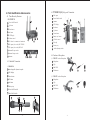
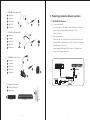
4. Parts Identification & Accessories
4-1 True-Diversity Receiver
1.US-1000D-TH
Power On/Off switch
Up button
Down button
Set button
LCD Display
Volume control
DC socket for connection of main unit
AF output, jack socket (AF UNBAL)
AF output, jack socket (AF BAL)
Antenna II input socket
Antenna I input socket
Antenna
4-2. Handheld Transmitter
Interchangeable dynamic capsule
LCD display
Down button
UP button
Set button
Battery tray
Power On/Off switch
8
8
9
10
11
12
Mute On/Off switch
1. Mh-8990-TH
4-3 PT-990B-TH(mi) Body-pack Transmitter
1. Mic. input
2. Power On/off switch
3. Antenna
4. LCD display
5. Set button
6. Up button
7. Down button
8. Battery tray button
9. AF level control
10. Belt clip
11. Battery tray
12. Audio adjusting sticker
4-4 Condenser Microphone
(1) CM-201 Lavalier Microphone
1. Microphone
2. Clip
3. Mini XLR
4. Windscreen
(2) CM-501 Lavalier Microphone
1. Microphone
2. Clip
3. Mini XLR
4. Windscreen
11
10
9
12

~7~
~6~
(3) CM-204 Headset Microphone
1. Microphone
2. Gooseneck
3. Neck-Frame
4. Mini XLR
5. Windscreen
(4) CX-504 Headset Microphone
1. Microphone
2. Gooseneck
3. Neck-Frame
4. Mini XLR
5. Windscreen
(5) CX-508W Wind Microphone
1. Microphone
2. Gooseneck
3. Neck-Frame
4. Mini XLR
5. Windscreen
4-5 Optional Accessories
1. Dual Rack Adaptor Set
2. Guitar Cable
RP-900 DR-900 GC-80
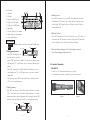
5. Preparing procedures & basic operation
5-1 US-1000D-TH Receiver
(1.) Power output connector
Plug in one end of AC/DC adaptor cable to DC input socket in the rear
panel of receiver, and plug another end into an AC outlet
(Step 1 of Figure 1)
(2.) Audio Output Connector
Connect one end of the AF output cable to the AF output socket in the
rear panel, then plug another end to the "MIC IN" input socket of a mixer
or amplifier.(Step 2 of Figure 1).
Receiver equipped with balanced XLR output and Unbalanced.3mm
output, choose the proper way for use.
(Figure 1)

~9~
~8~
Basic operation
POWER Turning the receiver on and off by pressing the POWER button.
SET
1. Setting group channel:
Press "SET" button three sec. till
the "Freq" show up and then
re-press "SET" button till the "Guoup"& "G" show up you can select group.
After that press "UP" or "DN" button one sec. to increase or decrease group
number.
Press "SET" button again the "GRUP"and"CH" starts showing up you can
select channel, press "UP" or "DN" button one sec. to increase or decrease
channel digit.
After there steps, press "SET" button again the "Store" will display on the
LCD, you can save the setting now.
2. Setting Frequency :
Press "SET" button three sec. till the "Freq" show up and then you can press
"UP" or "DN" button one sec. to increase or decrease frequency. In case the
frequeney meets the re-set group channel it willl be displayed. Re-press "SET"
button the "Store" will display on the LCD, you can save the setting now.
(3.) LCD panel
1. AF signal
2. RF signal
3. Display for GROUP mode
4. Display for LOCK mode
5. Display for set FREQ. mode
6. Main display
7. Diversity display (A or B antenna)
8. Battery display for the transmitter
9. Group channel display
Power On/Off SET UP
DN
Power On/Off SET UP
DN
3. Setting Lock-on
Press "SET" button three sec. re-press "SET" button three times, after these
procedure Press "UP" button for lock-on mode and "DN" button for lock-off
mode. Re-press "SET" button the "Store" will display on the LCD the lock
function could stored.
4. Relieved Lock-on
Press "SET" button three sec. till "Loc On" show up, to press "UP" button for
lock-on mode and "DN" button for lock-off mode. Re-press "SET" button the
"Store" will display on the LCD the lock function could stored.
5. Press any button the display shows "Loc On" during lock-on mock.
And it will not disappeared either electric off.
1. Insert 2 pcs 1.5V batteries into the battery tray. (figure 1)
2. After putting into the battery, switch on the power on/off. (figure 2)
(figure 1) (figure 2)
5-2 Handheld Transmitter
1.Mh-8990-TH

~11~
~10~
2. Setting group channel
1. Frequency displayed:
(1) group set up
Press "SET" button for three sec. till the "MHz" show up and then re-press
"SET" button till the group digit show up. Now you can press "UP" or "DN"
button one sec. to increase or decrease group number
(2) channel set up
After (1) press "SET" button again the frequency display starts showing up,
press "UP" or "DN" button one sec. to increase or decrease frequency digit.
(3) After (1) & (2) step, press "SET" button again the mic. will store the
frequency automatically.
2. Group displayed:
(1) Press "SET" button for three sec. till the group digit show up then re-press
"UP" or "DN" button one sec. to increase or decrease group digit.
(2) After (1) press "SET" button again the frequency display starts showing up,
press "UP" or "DN" button one sec. to increase or decrease frequency digit.
(3) After (1) & (2) step, press "SET" button again the mic. will store the frequency
automatically.
3. LCD operation
(1.) Up button
(2.) Down button
(3.) SET button
(figure 3)
1.
2.
3.
3. Setting Frequency
3.1 Frequency displayed:
Press "SET" button for three sec. till the "MHz" show up and then you can press
"UP" or "DN" button one sec. to increase or decrease frequency. Re-press "SET"
button again the mic. will store the frequency automatically.
3.2 Group displayed:
(1) Press "SET" button for three sec. till the group digit show up then re-press
"SET" button the frequency starts flashing.
(2) After (1) press "SET" button till the "MHz" show up and then re-press "UP" or
"DN" button one sec. to increase or decrease group digit.
(3) After (1) & (2) step, press "SET" button again the mic. will store the frequency
automatically.
4. Setting sensitivity
4.1 Frequency displayed :
Press "SET" button three sec. till "MHz" show up, re-press "SET" button the
group digit starts flashing, after these procedure please press "SET" button again
till frequency starts flashing then press "SET" to start the sensitivity setting.
4.2 Group displayed :
Press "SET" button three sec. till group digit show up, re-press "SET" the frequency
Starts flashing. Press "SET" button again till "MHz" show up, re-press "SET"
button till sensitivity displaying then you can proceed the sensitivity setting.
Press "UP" or "DN" button to increase or decrease sensitivity.
There are 4 sensitivity could be adjusted : 0dB, -6dB, -12dB, -24dB
5. Setting Lock-on
5.1 Frequency displayed :
Press "SET" button three sec. till "MHz" show up, re-press "SET" button the

~13~
~12~
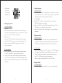
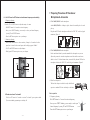
5-3 PT-990B-TH(mi) Body-pack Transmitter
(1.) Turning the transmitter on/off
The on/off switch is located on the top of the transmitter.
(2.) Inserting and changing the battery
1. The battery tray is located on the back of the transmitter.
2. Hold on to both belt clip buttons to release it.
3. Insert 2 pieces of UM-3 1.5V batteries. Remember to match correct polarity.
4. Directly slide the belt clip back.
(Figure 5) (Figure 6) (Figure 7)
group digit starts flashing, after these procedure please press "SET" button again
till frequency starts flashing then press "SET" button till sensitivity displaying
please press "SET" button to start the lock-on setting. Press "UP" button for
lock-on mode and "DN" button for lock-off mode. Re-press "SET" button the
lock function will store.
5.2 Group displayed :
Press "SET" button three sec. till group digit show up, re-press "SET" the
frequency. Starts flashing. Press "SET" button again till "MHz" show up,
re-press "SET" button till sensitivity displaying, press "SET" button till
"Loc OFF" starts flashing then you can proceed the lock-on setting. Press
"UP" button for lock-on mode and "DN" button for lock-off mode. Re-press
"SET" button the lock function will store.
6. Relieved Lock-on :
Press "SET" button three sec. till "Loc On" show up, then press "DN" button
plus "SET" button to store the lock-on relieved.
7. Press any button the display shows "Loc On" during lock-on model.
And it will not disappeared either electric off.
6. Preparing procedures
6-1 ( US-1000D-TH Receiver )
(1.) Setting the rubber pad
Four self-adhesive rubber pads are provided to ensure the stability.
They are to be placed on the bottom side of the receiver.
(2.) Connecting the antennas
The user-friendly US-1000D-TH antenna comes with easy mount on
socket for effortless connection. Connect two antennas on the
back of the receiver and align them upward.
(3.) Connecting the main unit
Plug in the DC connector on the back of the receiver
(DCV INPUT).
(4.) Connecting the amplifier/mixer console
Plug in the amplifier/mixer console to the
(AF OUT UNBAL / BAL ) sockets.
(5.) Turning the receiver on/off
Turn the receiver on by pressing the (POWER)
button.
(6.) Adjusting the AF output level
Use the AF output level control located on the front side of the receiver to adjust
the AF signal level that appears at output.
ANT. 1ANT. 2
Serial No.:
Freq. Range:
12-18V/500mA
DCV INPUT
AF OUTPUT
UNBAL .
AF OUTPUT
BALANCED
DCV INPUT
ANT. 1ANT. 2
Serial No.:
Freq. Range:
12-18V/500mA
DCV INPUT
AF OUTPUT
UNBAL .
AF OUTPUT
BALANCED
ANT.1 / ANT.2
AF output level
ANT. 1ANT. 2
Serial No.:
Freq. Range:
12-18V/500mA
DCV INPUT
AF OUTPUT
UNBAL .
AF OUTPUT
BALANCED
AF OUT UNBAL / BAL
power

~15~
~14~
UP button to activate "Lock mode"
-Hold on to UP button for 3 seconds to activate "Lock mode", press again to unlock.
(Prevent accidental programming or switching off)
6-4 Mh-8990 Press the SET button to select between frequency and sensitivity.
1. Frequency adjusting
Press the UP or DOWN button to adjust the setting of a menu.
-Hold SET button for 3 seconds to activate frequency.
-Once you see "MHZ" blanking, you are ready to select your desired frequency
by using UP and DOWN buttons.
-Press the SET button again to store your changes.
2. Sensitivity adjusting
-Press the SET button twice to select sensitivity. Lasting for 3 seconds at the first
press, then 1 second for the second press, and the display appears "SenSit".
-Use UP and DOWN buttons to adjust changes.
-Finally press SET button again to store your changes.
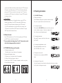
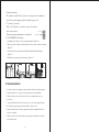
7. Preparing Procedures Of Condenser
Microphone & Accesories
(1) With CM-201/CM-501 Lavalier microphone
Attach CM-201/CM-501 to clothing, tie, lapel, where is the suitable place of sound
pick-up.
Plug the mini XLR on the microphone cable into the "MIC. IN" on the body-pack
transmitter. (Figure 8)
(2) With CM-204/CX-504 Headset microphone
Put the neck-frame behind your neck meanwhile fix the temples on your ears.
Adjust the gooseneck to aim the microphone toward the suitable sound source,
which is about 1.5-2 inches distance from your mouth. Plug the mini XLR on the
microphone cable into the "MIC. IN" on the body-pack transmitter. (Figure 9)
(3) Dual Rack Adaptor set
The dual rack adaptor is available to unify the half rack
space into a standard EIA size with single or dual units.
Basic operation
1. Frequency adjusting
-Hold SET button for 3 seconds to activate frequency.
-Once you see "MHZ" blanking, you are ready to select your
desired frequency by using UP and DOWN buttons.
-Press the SET button again to store your changes.
UP
DOWN
SET
(Figure 8)
(Figure 9)
MIC IN

~16~
2. Sensitivity adjusting
-The sensitivity control(AF level control) is in the up-left of the transmitter's
back. Please use the adjusting sticker to adjust the proper level.
3. To activate "Lock mode"
-Hold on to UP button for 3 seconds to activate "Lock mode",
press again to unlock.
(Prevent accidental programming or switching off)
(4) With CX-508W Wind Microphone
1. Outsanding for saxophone, brass, woodwind instruments. (Figure 10)
2. Flesible gooseneck together with adjustable axis allow accurate sound source aiming.
(Figure 11)
3. Clamp with elastic grip ensures stable holding instrument without damaging
(Figure 12)
4. Windscreen to prevent pop noise effectively. (Figure 13)
8. Recommendation
1. In order to achieve the optimum reception condition and also extend the operating
distance, please leave a "open space" between the receiver and transmitter.
2. Keep the devices away from the metal objects or any interference sources, at
least 50 cm.
3. To avoid the feed-back effect, don't leave the mic. to aim at the speakers directly.
4. For best pick-up pattern, please hold the middle of the mic. body.
5. Remove batteries from the battery compartment when the transmitter will not be
used for a long time.
6. When you need to replace the batteries, please replace both batteries at the same
time with new ones.
AF level control
Audio adjusting sticker
(Figure 10) (Figure 11) (Figure 12) (Figure 13)
-
 1
1
-
 2
2
-
 3
3
-
 4
4
-
 5
5
-
 6
6
-
 7
7
-
 8
8
-
 9
9
-
 10
10


Ask a question and I''ll find the answer in the document
Finding information in a document is now easier with AI
Related papers
Other documents
-
ITC T-521UH Owner's manual
-
Panasonic WM-KG645 User manual
-
Kmart 42959540 User manual
-
-
Sense SE-500-DEH-T Owner's manual
-
Binary SE-300-WT-HAND Owner's manual
-
Optimus US-902DC User manual
-
Sense SE-350-WT-HAND Owner's manual
-
CAD Audio Multi Channel Wireless UHF Microphone System Operating instructions
-
Audio-Technica ATW-1663 User manual