Page is loading ...

Headquarters and Sales
Lake Shore Cryotronics, Inc.
575 McCorkle Boulevard Westerville, Ohio 43082
Phone 614-891-2244 Fax 614-818-1600
All specifications subject to change. Rev 9/18/2007
Features
High stability operation from 1.5 K to 475 K
Active cryogenic control of the cold head, mid-stage,
and radiation shield
Reduces potential for sample condensation by allowing
sample to remain at room temperature while the system
cools to 1.5 K
Measurements from DC to 67 GHz
Accommodates up to 25 mm (1 in) diameter wafers
Configurable with up to four micro-manipulated probe arms
Probe arms with 3-axis adjustments and ±5° theta
planarization
Cables, shields, and guards minimize electrical noise and
thermal radiation losses
High resolution optical system
Tabletop design with small footprint
Options and accessories for customization to specific
research needs
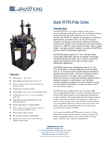
Model TTP4-1.5K Probe Station
Introduction
The Model TTP4-1.5K is a versatile cryogenic
micro-manipulated probe station used for non-
destructive testing of devices on full and partial
wafers up to 25 mm (1 in) in diameter. The
TTP4-1.5K is a platform for measurement of
electrical, electro-optical, parametric, high Z, DC,
RF, and microwave properties of materials and test
devices. Nanoscale electronics, quantum wires and
dots, and semiconductors are typical materials
measured in a TTP4-1.5K. A wide selection of
probes, cables, sample holders, and options makes
it possible to configure the TTP4-1.5K to meet
your specific measurement applications.
The TTP4-1.5K operates over a temperature range
of 1.5 K to 475 K. The probe station provides
efficient temperature operation and control with a
continuous refrigeration system using either
helium or nitrogen. Vapor-cooled shielding
optimizes efficiency and intercepts blackbody
radiation before it reaches the sample. Two control
heaters on the cold head minimize temperature
gradients across the sample and, along with the
mid-stage and radiation shield heaters, provide
the probe station with fast thermal response.
The TTP4-1.5K is user-configured with up to four
ultra-stable micro-manipulated stages, each
providing precise 3-axis control of the probe
position to accurately land the probe tip on
device features. Proprietary probe tips in a variety
of sizes and materials minimize thermal mass and
optimize electrical contacts to the device under
test (DUT). Probe tips are thermally linked to the
mid-stage to prevent heat transfer to the DUT.
For increased versatility, TTP4-1.5K options
include vibration isolation systems, LN2 Dewar kit,
higher magnification monoscopes, vacuum turbo
pumping system, and fiber optic probe arm
modification.

2 ©2007 Lake Shore Cryotronics, Inc. All specifications subject to change. TTP415K Rev 9/18/2007
Applications
Electrical and electro-optical measurements over a
wide temperature range
RF and microwave
Parametric testing
Shielded/guarded/low noise characterization
High Z
Non-destructive, full wafer testing
Materials
Nanoscale electronics (carbon nanotube transistors,
single electron transistors, molecular electronics,
nanowires, etc.)
Quantum wires and dots, quantum tunneling
Single electron tunneling (Coulomb blockade)
Basic semiconductor devices including organics,
LEDs, and dilute magnetic semiconductors
Specifications
Temperature
Operating temperature range—overal
l
1.5 K to 475 K*
ZN50 DC/RF probe with low RF cryogenic coax cable 1.5 K to 475 K*
ZN50 DC/RF probe with high RF semirigid coax cable 1.5 K to 400 K*
GSG microwave probe with semirigid coax cable 1.5 K to 400 K*
Temperature control (heaters)
1.5 K cold head stage 25 W (2 parallel heaters, 12.5 W each)
4.2 K mid-stage 50 W
Radiation shield 100 W
Probe arm Measurement only
*Selectable equipment
Probe Arm Adjustments
Travel
X axis 51 mm (2 in)
Y
axis 25 mm (1 in)
Z axis 18 mm (0.7 in)
Translation resolution
X axis 20 µm
Y
and Z axes 10 µm
Theta planarization* ±5°
*Included with microwave probes

©2007 Lake Shore Cryotronics, Inc. All specifications subject to change. TTP415K Rev 9/18/2007 3
Frequency Range
ZN50 DC/RF probe frequency range
Tungsten with cryogenic coax cable 0 to 50 MHz*
Tungsten with semirigid coax cable 0 to 1 GHz*†
Paliney 7 with cryogenic coax cable 0 to 50 MHz*
Paliney 7 with semirigid coax cable 0 to 1 GHz*†
BeCu with cryogenic coax cable 0 to 50 MHz*
BeCu with semirigid coax cable 0 to 1 GHz*†
GSG microwave probe frequency range
Low frequency with K connecto
r
0 to 40 GHz*
Mid frequency with 2.4 mm connecto
r
0 to 50 GHz*
High Frequency with 1.8 mm connecto
r
0 to 67 GHz*
* Selectable equipment
† S21 > -10 dB up to 1 GHz, except for a (-40 dB) spike between 400 MHz and 800 MHz depending on probe model and placement; S11 < -3 dB up to 1 GHz
Optical
Optical viewpor
t
—located on top lids Ø54 mm (2.1 in) outer window and Ø51 mm (2 in) inner window
Outer, clear fused quartz 99% IR transmittance
Inne
r
IR absorbing with narrow band visible light transmittance
Optical resolution—monoscope
7:1 zoom 5 µm
12.5:1 zoom 4 µm*
16:1 zoom 3 µm*
*Selectable equipment
Sample Holder (Chuck)
Maximum sample size—overall Up to Ø25 mm (1 in)
SH-1.00-G, grounded chuck Up to Ø25 mm (1 in) and 475 K
SH-1.00-I, isolated chuck Up to Ø25 mm (1 in) and 400 K*
SH-1.00-C, coaxial chuck Up to Ø25 mm (1 in) and 400 K*
SH-1.00-T, triaxial chuck Up to Ø25 mm (1 in) and 400 K*
*Selectable equipment

4 ©2007 Lake Shore Cryotronics, Inc. All specifications subject to change. TTP415K Rev 9/18/2007
Standard Equipment
Open cycle sample stage refrigerator 1.5 K to 475 K
1.5 K cold head stage temperature sensor Lake Shore Model DT-670-SD-1.4H calibrated silicon diode
1.5 K cold head stage heater 25 W (2 parallel heaters, 12.5 W each)
1.5 K cold head stage rotary pump with
oil eliminator and hose
14.7 CFM at 60 Hz
4.2 K mid-stage temperature sensor Lake Shore Model DT-670C-CU silicon diode
4.2 K mid-stage heater 50 W
Cooled radiation shield and cooled IR-absorbing window above the sample
Temperature sensor Lake Shore Model DT-670C-CU silicon diode
Radiation shield heater 100 W
Removable top lid with viewpor
t
Ø51 mm (2 in) window
Temperature controller Two Lake Shore Model 332S and one Model 142 200 W (2 channels, 100
W each) power supply (independent regulation of 1.5 K cold head stage,
4.2 K mid-stage, radiation shield, and probe arm temperature
monitoring)
Vacuum chamber
Diameter 15.2 cm (6 in)
Removable top lid with clear fused quartz viewpor
t
Ø54 mm (2.1 in) window
Probe ports 4 equally spaced surround the sample thermal radiation shield
Machined aluminum base plate 45.7 cm2(18 in2) with four 19.1 cm (7.5 in) legs
Four XYZ precision micro-manipulated probing stages
Probe arms, thermal radiation shields, stainless steel welded bellows, and feedthrough ports
Thermally linked probe mounts Probe mounts and radiation shield are thermally anchored to the mid-
stage; one probe mount includes a platinum temperature sensor installed
and wired to a 6-pin feedthrough
Grounded sample holder SH-1.00-G, accommodates up to a Ø25 mm (1 in) sample with a Ø25 mm
(1 in) probe area
Optics
Zoom 70 monoscope 7:1 zoom with 5 µm resolution
Color CCD camera
Swing arm Optics can be manipulated to view any part of the sample or wafer, and
can be retracted and swung away to allow access to the top of the
vacuum chamber for sample exchange
Video monitor High resolution, 17-inch
Sample illumination Coaxial via fiber optic or ring light from an adjustable light source and
power supply (must specify sample illumination at time of order)
NOTE: Coaxial illumination is recommended for highly reflective materials
High efficiency helium transfer line with foot valve for precise flow regulation
Basic tools, spares, and cleaning kit

©2007 Lake Shore Cryotronics, Inc. All specifications subject to change. TTP415K Rev 9/18/2007 5
Probes, Probe Tips, and Cables — Required User Configurable Equipment
ZN50 DC/RF PROBES
Ideal for: DC biasing, low/high frequency measurements, low noise shielded,
and low-leakage guarded measurement
ZN50 probe base incorporates a pair of copper braids that connect to the
sample stage to dynamically cool/heat the probe to the sample temperature
SMA connector mounted directly to a replaceable alumina ceramic blade with
a 50 Ω stripline routed to the probe contact
Part number (probe body) Description
ZN50-26U
50 Ω stripline probe body mount
(each probe body mount requires a
ceramic blade—selectable below)
*Maximum frequency 50 MHz with Z50-CU-SS-3650-G or Z50-CU-SS-3650-T cable; maximum frequency 1 GHz with K-085-K cable
ZN50 DC/RF CABLES
Part number Cable type Connector
type
Feedthrough
type
Measurement
configuration
Maximum
frequency
Maximum
temperature
Z50-CU-SS-3650-G Ultra-miniature
cryogenic coax SMA BNC Shielded 50 MHz 475 K
Z50-CU-SS-3650-T Ultra-miniature
cryogenic coax SMA 2-lug triax Low leakage 50 MHz 475 K
K-085-K-07
Stainless
semirigid
microwave coax
K
Loss-less
compression
seal
High frequency 1 GHz* 400 K
* S21 > -10 dB up to 1 GHz, except for a (-40 dB) spike between 400 MHz and 800 MHz depending on probe model and placement; S11 < -3 dB up to 1 GHz
Part number (ceramic blade) Tip material Maximum frequency (GHz) Tip radius (µm)
ZN50R-03-W
Tungsten
1*
3
ZN50R-10-W 10
ZN50R-25-W 25
ZN50R-03-P7
Paliney 7
3
ZN50R-10-P7 10
ZN50R-25-P7 25
ZN50R-03-BeCu
BeCu
3
ZN50R-10-BeCu 10
ZN50R-25-BeCu 25
ZN50R-100-BeCu 100
ZN50R-200-BeCu 200
We understand that today’s
researcher requires flexibility.
Our wide selection of probes,
cables, sample holders, and
options make it possible to
configure a probe station to
meet your specific
measurement applications.

6 ©2007 Lake Shore Cryotronics, Inc. All specifications subject to change. TTP415K Rev 9/18/2007
GSG MICROWAVE PROBES
Coplanar waveguide probe with ground-signal-ground (GSG) contact geometry
User specified pitch (spacing)
Optimized low thermal conductivity coax leading to low thermal conductivity tips
Includes a copper braid assembly to cool the probe to near sample temperature
Probes are limited to 400 K
A separate theta planarization module with ±5° rotation mechanism is also provided
Part Number Connector Type Maximum Frequency (GHz) Pitch (µm)
GSG-050-40A-26U-D
K 40
50
GSG-100-40A-26U-D 100
GSG-150-40A-26U-D 150
GSG-200-40A-26U-D 200
GSG-250-40A-26U-D 250
GSG-050-50A-26U-D
2.4 mm 50
50
GSG-100-50A-26U-D 100
GSG-150-50A-26U-D 150
GSG-200-50A-26U-D 200
GSG-250-50A-26U-D 250
GSG-050-67A-26U-D
1.8 mm 67
50
GSG-100-67A-26U-D 100
GSG-150-67A-26U-D 150
GSG-200-67A-26U-D 200
GSG-250-67A-26U-D 250
GSG MICROWAVE CABLES
Loss-less compression seal
Semirigid with stainless steel outer jacket, silver plated BeCu inner conductor, and Teflon® dielectric
Part number Cable type Feedthrough
type
Maximum
temperature
Connector
type
Maximum
frequency
K-085-K-07 Stainless semirigid
microwave coax
Loss-less
compression
seal
400 K
K 40 GHz
2.4-085-2.4-07 2.4 mm 50 GHz
1.8-085-1.85-07 1.8 mm 67 GHz

©2007 Lake Shore Cryotronics, Inc. All specifications subject to change. TTP415K Rev 9/18/2007 7
SAMPLE HOLDERS (CHUCKS)
Typical sample holder configuration characterized by:
Leakage resistance between
Top surface and guard
Guard and ground
Capacitance between
Top surface and guard
Guard and ground
Types of sample holders
Grounded sample holder—sample mount surface
at system ground
Isolated sample holder—backside contact not needed; sample mount surface is electrically non-conductive and
isolated from ground
Coaxial sample holder—backside contact can be made; sample mount surface is isolated from ground
Triaxial sample holder—guarded backside contact can be made; sample mount surface has guarded isolation
from ground
Part number Measurement
configuration
Separate feedthrough
required
Maximum sample
(diameter)
Maximum
temperature
SH-1.00-G Grounded No
Ø25 mm (1 in)
475 K
SH-1.00-I Isolated
400 K
SH-1.00-C Coaxia
l
Yes*
SH-1.00-T Triaxia
l
Yes**
*Coaxial sample holders require one FT-BNC or FT-TRIAX feedthrough as listed below
**Triaxial sample holders require one FT-TRIAX feedthrough as listed below
Part number Description
FT-BNC Coaxial feedthrough and coax cable, installed and wired
FT-TRIAX Triaxial feedthrough and coax cable, installed and wired
Equipment Options
Part Number Description
PS-FOA
Fiber optic probe arm modification. Transmit or receive light or IR/UV radiation. Fiber optic terminated with SMA
connector or compression feedthrough. (Fiber optic wire not included. Fiber optic and probe cannot be used
simultaneously.)
PS-Z12.5 12.5:1 zoom monoscope upgrade for 4 µm resolution NOTE: upgrade is not field-installable
PS-Z16 16:1 zoom monoscope upgrade for 3 µm resolution NOTE: upgrade is not field-installable
PS-DPC Automatic Dewar (gas) pressure controller, regulates Dewar liquid flow
PS-V81TP Turbo pumping system—includes Varian V-81 Turbo Pump cart with DS 102 backing pump, vacuum gauging for high
vacuum and fore line, controller, and adaptors (specify 110 V/60 Hz or 220 V/50 Hz)
PS-V81DP Turbo pumping system—includes Varian V-81 Turbo Pump cart with oil free backing pump, vacuum gauging for
high vacuum and fore line, controller, and adaptors (specify 110 V/60 Hz or 220 V/50 Hz)
PS-LN2 Nitrogen Dewar with stainless fittings, gauges, and adaptors; allows LN2 use with the LHe transfer line
PS-PLVI-25 Pump-line vibration iso
l
ator—includes NW-25 fittings, 1 m stainless steel bellows, clamps, and rings (placed
between pump cart and system); requires one bag of cement
PS-LVS Low vibration, heavy PVC constructed non-magnetic stand with sand weighted legs and brass fittings NOTE:this
option minimizes system vibration displacement at all frequencies
PS-TTVIS
Pneumatic tabletop vibration isolation system—compact pneumatic isolator with sel
f
-leveling (isolator resonance:
vertical 3.2 Hz, horizontal 3.6 Hz; isolation efficiency at 10 Hz: vertical 90%, horizontal 96%; amplification at
resonance: vertical 12 dB, horizontal 10 dB); requires PS-LVS (ordered separately) and 80 psi nitrogen or air
PS-OAC Oi
l
-less compressor for PS-TTVIS (only available in 110 V)
PA-SEN Probe arm modification with platinum temperature sensor installed and wired to a 6-pin feedthrough
R
Backside signal
Device on
wafe
r
Probe signal
Guard
Backside guard
Guard
Base of chuck (at system ground)
Vacuum chamber (system ground)
Top of chuck
(sample mount surface)
Insulator

8 ©2007 Lake Shore Cryotronics, Inc. All specifications subject to change. TTP415K Rev 9/18/2007
Equipment Options, continued
PA-TTP4 Probe arm and base for TTP4-1.5K
MMS-TTP4 Micro-manipulated stage for TTP4-1.5K
CS-5 Calibration substrate for GSG probes. Pad size: 50 µm2; calibration type: SOLT (short-open-load-through),
LRL (line-reflective-line), LRM (line-reflective-match); pitch range: 75 to 250 µm
CS-15 Calibration substrate for GSG probes. Pad size: 25 µm2; calibration type: SOLT (short-open-load-through),
LRL (line-reflective-line), LRM (line-reflective-match); pitch range: 40 to 150 µm
Lake Shore Cryotronics is a leading supplier of cryogenic, superconducting
magnet-based, electromagnet-based, high vacuum, and load-lock probe stations.
We offer a full line of standard probe stations to meet your research requirements.
Our standard line of probe stations includes:
Model TTP4
Up to four micro-manipulated probe stages
Temperature range capabilities from 3.2 K to 475 K
Up to 51 mm (2 in) diameter wafer capabilities
Model TTP4-1.5K
Up to four micro-manipulated probe stages
Standard temperature range from 1.5 K to 475 K
Up to 25 mm (1 in) diameter wafer capabilities
Model TTP6
Up to six micro-manipulated probe stages
Temperature range capabilities from 3.2 K to 475 K
Up to 51 mm (2 in) diameter wafer capabilities
Model FWP6
Up to six micro-manipulated probe stages
Standard temperature range from 4.5 K to 475 K
Up to 10.2 cm (4 in) diameter wafer capabilities
Model LLTTP6
Load-lock — for fast sample exchange at any temperature
Up to six micro-manipulated probe stages
Standard temperature range from 10 K to 400 K
Up to 51 mm (2 in) diameter wafer capabilities;
up to 12.7 mm (0.5 in) with load-lock assembly
Model HFTTP4
1 T horizontal field split pair superconducting magnet
Up to four micro-manipulated probe stages
Temperature range capabilities from 2 K to 400 K with
field on or off
Up to 25 mm (1 in) diameter wafer capabilities
Model VFTTP4
2.5 T vertical field solenoid superconducting magnet
Up to four micro-manipulated probe stages
Temperature range capabilities from 2 K to 400 K
with field on or off
Up to 51 mm (2 in) diameter wafer capabilities
Model EMTTP4
0.55 T horizontal (in-plane field) electromagnet
Up to four micro-manipulated probe stages
Standard temperature range from 5 K to 475 K
Up to 25.4 mm (1 in) diameter wafer capabilities
Model HVTTP6
High vacuum to 10-7 torr
Up to six micro-manipulated probe stages
Temperature range capabilities from 2 K to 475 K
Up to 51 mm (2 in) diameter wafer capabilities
/


