TBCCP1-400K600

TEKBOX TBCCP1-400K600 User manual

  • Hello! I've reviewed the datasheet for the Tekbox TBCCP1-400K600 RF Current Monitoring Probe. It details the probe’s specifications, such as its wide bandwidth and frequency range, transfer impedance, and application notes. I understand it’s designed for RF current measurement and is suited for use with loop antennas. I'm ready to answer your questions about the device.
  • What is the frequency range of the TBCCP1-400K600?
    What type of connectors does the TBCCP1-400K600 have?
    What is the maximum primary RF current?
V1.0
TBCCP1-400K600
COAXIAL RF CURRENT MONITORING PROBE
1
1 Introduction
The TBCCP1-400K600 is a coaxial RF current monitoring probe, expanding the Tekbox
product range of affordable EMC pre-compliance test equipment.
The probe has a 3 dB bandwidth from 400 kHz to 600 MHz and a very flat response from 1
MHz to 200 MHz. The transimpedance is characterized over the frequency range from 10 Hz
to 100 MHz. The TBCCP1-400K600 is primarily designed as transducer for passive loop
antennas or for measurement of RF currents in coaxial cables.
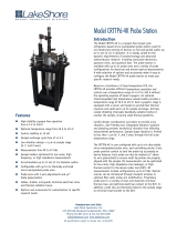
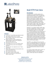
Picture 1: TBCCP1-3K100 RF current monitoring probe
The probe is equipped with N-connectors. An attachment with a ¼” thread permits
connectivity to standard tripods.
2 Specification
Characterized frequency range: 10 Hz to 600 MHz
Transfer impedance: 23 dB Ohm
3 dB bandwidth: 400 kHz to 600 MHz, typ.
Dimensions: 76 mm x 102 x 69 mm
Weight: 400 g
Connector type: N female
Max. primary current (RF): 12 A
Max. core temperature: 125 °C
V1.0
TBCCP1-400K600
COAXIAL RF CURRENT MONITORING PROBE
2
3 Transfer impedance
Figure 1: transfer impedance, 10 Hz 1 GHz, typical data
4 Coaxial Path Insertion loss (S21)
Figure 2: S21, insertion loss of the coaxial path, 10 Hz 1 GHz, typical data
V1.0
TBCCP1-400K600
COAXIAL RF CURRENT MONITORING PROBE
3
5 Coaxial Path Matching (S11)
Figure 3: S11, impedance matching of the coaxial path, 10 Hz 1 GHz, typical data
6 Application
The TBCCP1-400K600 is primarily designed as current transducer for passive loop antennas.
It will provide a low antenna factor / good sensitivity over a wide frequency range.
Combined with a 185 cm length slotted coaxial cable, it will form a passive loop antenna with
a diameter of 60 cm. The magnetic antenna factor will have a value of approximately -18
dBS/m.
When used as transducer for a passive antenna, a typical sensitivity of -22 dBµA/m can be
achieved. This is sufficient for all CISPR xx radiated emission measurments in the frequency
range from 9 kHz to 30 MHz.
For more details, download the application note Loop Antenna Basics.pdf from the Tekbox
website.
V1.0
TBCCP1-400K600
COAXIAL RF CURRENT MONITORING PROBE
4
7 Typical transfer impedance table
The table below shows typical transfer impedance data of a TBCCP1-400K600 current probe.
Each current probe is delivered with its corresponding measurement protocol. This data can
be used for the creation of a correction file for EMCview or similar EMC measurement
software. The transfer impedance in dBΩ subtracted from the analyzer reading in dBµV gives
the corrected reading in dBµA.
Refer to the application notes of EMCview on how to create a current probe correction file,
download a file with typical data from the Tekbox website or simply select the file from the
installed correction file directory.
Frequency [MHz]
transfer impedance [dBΩ]
Frequency [MHz]
transfer impedance [dBΩ]
0.00001
-62.56
1
22.57
0.000025
-58.21
2.5
22.74
0.00005
-56.10
5
22.82
0.000075
-50.92
7.5
22.89
0.0001
-48.21
10
22.95
0.00025
-40.06
20
23.15
0.0005
-34.26
30
23.19
0.00075
-30.77
40
23.25
0.001
-28.20
50
23.26
0.00125
-26.37
55
23.26
0.0015
-24.76
60
23.25
0.00175
-23.49
65
23.26
0.002
-22.30
70
23.25
0.00225
-21.29
75
23.24
0.0025
-20.39
80
23.24
0.005
-14.34
85
23.25
0.0075
-10.83
90
23.24
0.01
-8.33
95
23.24
0.025
-0.39
100
23.24
0.05
5.55
200
23.51
0.075
8.98
300
24.41
0.1
11.34
400
25.57
0.25
18.04
500
25.70
0.5
21.32
550
25.53
0.75
22.28
600
25.53
Table1: Transfer impedance: 10 Hz to 600 MHz, typical data
V1.0
TBCCP1-400K600
COAXIAL RF CURRENT MONITORING PROBE
5
8 Calibration
Tekbox coaxial RF current probes do not need a calibration fixture for the measurement of the
transfer impedance.
Figure 4: S21, transimpedance measurement set up
Calculate the transfer impedance ZT using the formula below:
ZT [dBΩ] = Pin [dBm] – Pprobe [dBm] +34 dB
or simply
ZT [dBΩ] = S21 [dB] +34 dB
9 Ordering Information
Part Number
Description
TBCCP1-400K600
RF surface current monitoring probe, beech-wood box,
calibration protocol 1kHz 400 MHz
10 History
Date
Author
Changes
1.7.2022
Mayerhofer
Creation of the preliminary document
www.tekbox.com
TekBox Digital Solutions Vietnam Pte. Ltd.
Factory 4, F4, Lot I-3B-1, Saigon Hi-Tech Park, Tan Phu Ward, District 9, Ho Chi Minh City, Vietnam
/