Page is loading ...

Central Battery Systems CCU 12V And CCU 24V Series
1
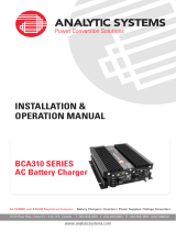
Figure D
USER MANUAL
Central Battery Systems by CCU 12V And CCU 24V Series or the central control unit is used to detect
any abnormalities of the main power distribution system. In case of error or emergency, the unit is
designed to allow the emergency lighting system to bear large loads or larger loads than that the
automatic emergency light (complete unit) can. The 12 VDC or 24 VDC unit is compatible with halogen
lamp or MR16 LED lamp. The unit installation and usage are centrally controlled so that it supplies power
to the lamp installed.
Features

CCU12V Series
Rated Capacity 620W 720W 1000W 1100W 1400W 1900W
Input Voltage
Frequency 50Hz
Output
Voltage
12VDC (Battery Mode)
Battery
Battery Rated Voltage
12 V
Charging Current
0-50A0-35A0-20A
Protections
Operate Temperature +10°C To +40°C
Size LxWxH ( mm )
620 x 350 x 750 620 x 400 x 950
CCU 12V Series
500W 600W 700W 950W 1100W 1200W 1440W 2200W
- AC, DC Fuse
- AC Under Voltage Protection
- Battery Low Voltage Cut-O
220 Vac 10%
+
_
CCU24V Series
Rated Capacity 1900W
Input Voltage
Frequency 50Hz
Output
Voltage
24VDC (Battery Mode)
Battery Sealed Lead-Acid Battery
Sealed Lead-Acid Battery
Battery Rated Voltage
24 V
Charging Current
0-35A0-25A0-15A
Protections
Operate Of Temperature
+10°C To +40°C
Size LxWxH ( mm )
620 x 300 x950 620 x 400 x 950
CCU 24V Series
220 Vac 10%
+
_
- AC. Fuse
- AC, DC Circuit Breaker
- Output Circuit Breaker
- AC. Input Over & Under Voltage
Protection
- Battery Low Voltage Cut-O
2
Technical Specifications

ABB
OUT 1
ABB
OUT2
ABB
OUT3
ABB
OUT4
Circuit Breaker Output 1,2,3,4
ABB
AC INPUT
L N
ABB
BATTERY
Circuit Breaker AC input Circuit Breaker Battery
220
24
AC. VOLTMETER
DC. VOLTMETER
LED H1
LED Charge/Full
SWITCH TEST
AC. FUSE
LED MAIN
LED DC.POWER
LED FAIL
3
Indicators
Indicating the input voltage.
Indicating the battery voltage.
Indicating the status of the input under voltage or over voltage.
Indicating charging status.
For testing the device’s availability (during normal circumstance)
Short-circuit protection of AC input.
Indicating the status of the input voltage of 220VAC.
Indicating the status of the output voltage.
Indicating the failure status of the control unit.
Installation and Operation
1. The inverter must be installed on the floo. Check the installation to make sure the unit is properly
secured to prevent possible accidents.
2. The inverter should be installed indoors away from direct sunlight and rain or moisture.
3. Position to connect Circuit Breaker Battery, Circuit Breaker Ac input, and Circuit Breaker Output 1,2,3,4
Illustration for number 3

Battery 12V
Battery 12V Battery 12V
Battery 12V
Battery 12V Battery 12V
Battery 12V Battery 12V
Battery 12V
220
24
4
4. Shut o every Circuit Breaker for preparing to connect AC Input, Load Output and Battery.
5. Connect the cables securely to the battery terminals to prevent damage (for models that does not
come with the battery preconnected). Connect the cables as shown in the wiring diagram for the battery
for model CCU12 VDC and CCU24 VDC. Connect the positive (+) and negative (-) cables correctly.
Diagram showing how to correctly connect the battery
Figure showing the indications at the front of the unit
Connecting a 12 Volt battery. Connecting a 24 Volt battery.
Connection for increasing the capacity
of a 12 Volt battery.
Connection for increasing the capacity
of a 24 Volt battery.

OUTPUT
OUTPUT 1 OUTPUT 2
OUTPUT 1 OUTPUT 2 OUTPUT 3
OUTPUT 1 OUTPUT 2 OUTPUT 3 OUTPUT 4
5
6. Connect the load to the terminal output of the central battery system. Check the short circuit of the
load and the total wattage of each CCU 12V and CCU24V for how many outputs are there, then the
output should be properly connected with the Load Output inside the cabinet at the power connector
of the output of CCU 12 and CCU24 by connecting the wires must be corrected by connecting the red
positive light to the positive (+) at the positive electrode (+) and the black positive light to the negative (-)
at the negative electrode (-). Connecting the output wires, each model may have more than 1 point, at
most 4 output points, each output current should not be more than 50 Amp for general products and
check the internal order that the wiring point fasten firmly, is not lose or has scraps, must not be in the
cabinet, may cause a short circuit.
Diagram showing how to connect the load to the Output terminal
Diagram showing how to connect the load to the Output terminal
Method 1, connection for 1 Output.
Method 3, connection for 3 Output. Method 4, connection for 4 Output.
Method 2, connection for 2 Output.

INPUT 220VAC
L GN
220
24
AC. VOLTMETER
DC. VOLTMETER
LED H1
LED Charge/Full
LED MAIN
LED DC.POWER
LED FAIL
6
7. Connect the AC.Input cable to the Input 220 VAC terminal inside the unit. The Line cable should be
connected to the L terminal, Neutral cable to the N terminal and Ground cable to the G terminal.
All cable connections should be secured and no foreign objects should be in the unit that could cause
a short-circuit.
8. Test the battery power input into the unit by setting the DC Circuit Breaker to ON, the indicators on
the unit should show the following.
Diagram showing how to connect the AC.Input cable to the terminal
Figure showing the indications at the front of the unit
The indicator is not showing.
Indicating the battery voltage.
The indicator showing that the unit is using
the power from battery should be on.
The indicator is not showing.
The indicator is not showing.
The indicator showing that the unit is using
the power from battery should be on.
The indicator is not showing.

AC. VOLTMETER
DC. VOLTMETER
LED H1
LED Charge/Full
LED MAIN
LED DC.POWER
LED FAIL
220
24
220
24
AC. VOLTMETER
DC. VOLTMETER
LED H1
LED Charge/Full
LED MAIN
LED DC.POWER
LED FAIL
7
9. Provide the unit with a 220VAC current by setting the AC Input Circuit Breaker to ON, the indicators
on the unit should show the following.
10. Setting the AC Input Circuit Breaker to ON.
Figure showing the indications at the front of the unit
Figure showing the indications at the front of the unit
Shows the current level at the Input to be about 220VAC.
Indicating the battery voltage.
The indicator is not showing.
The indicator showing that the battery is charging should be on .
The indicator showing that the unit is receiving a 220VAC
current should be on.
The indicator is not showing.
The indicator is not showing.
Shows the current level at the Input to be about 220VAC.
Indicating the battery voltage.
The indicator is not showing.
The indicator showing that the battery is charging should be on.
The indicator showing that the unit is receiving a 220VAC
current should be on.
The indicator is not showing.
The indicator is not showing.

220
24
AC. VOLTMETER
DC. VOLTMETER
LED H1
LED Charge/Full
LED MAIN
LED DC.POWER
LED FAIL
220
24
AC. VOLTMETER
DC. VOLTMETER
LED H1
LED Charge/Full
LED MAIN
LED DC.POWER
LED FAIL
8
12. Set the AC Input circuit breaker to On to test the unit by pressing the TEST switch.
Note : While pressing the TEST switch, AC. VOLTMETER and LED MAIN light will turn o for 5 seconds.
Figure showing the indications at the front of the unit
Figure showing the indications at the front of the unit
The indicator is not showing.
Indicating the battery voltage.
The indicator showing that the unit is using the power
from battery should be on.
The indicator is not showing.
The indicator is not showing.
The indicator showing that the unit is using the power
from battery should be on.
The indicator is not showing.
Shows the current level at the Input to be about 220VAC.
Indicating the battery voltage.
The indicator showing that the unit is using the power
from battery should be on.
The indicator is not showing.
The indicator showing that the unit is receiving a 220VAC
current should be on.
The indicator showing that the unit is using the power from
battery should be on.
The indicator is not showing.
11. Set the AC Input Circuit Breaker to O to simulate the power outage status. The unit will display
the status as follows.

220
24
220
24
9
Malfunction indicator of AC Input (LED H.1)
1. Under Volt is AC INPUT status, power supply of 0-160VAC. The LED H.1 will turn on to indicate with
red light.
2. Over Volt is AC Input status, power supply over 270VAC. The LED H.1 will turn on to indicate with
orange light.
Testing the unit’s operation
1. To test the operation of the unit, user can switch the AC Input circuit breaker to "OFF" position, the unit
will immediately supply voltage to emergency light.
2. To stop testing the operation of the unit, user can switch the AC Input circuit breaker to "ON" position,
the unit will turn o and return to ready mode.
Figure showing the indications at the front of the unit
Figure showing the indications at the front of the unit

10
Maintenance
1. Every 1 month, to test the Backup power supply system, user can switch the AC input circuit breaker to
"OFF" position for 30 minutes, then switch the AC input circuit breaker back to "ON" position.
2. Every 6 months, to test the Backup power supply system, user can switch the AC input circuit breaker to
"OFF" position for 60 minutes, then switch the AC input circuit breaker back to "ON" position.
Initial Trouble Shooting
Problem
Cause What to do
- 220 VAC light not getting to
the unit.
- The Backup power supply of the
unit has failed .
- Emergency light only turns on for
a short time after the power went
out.
- The unit shows failure status.
- The power socket might not have any power.
- Circuit Breaker Main is turn o or in the OFF
position.
- Fuse AC. Input is in unavailable condition.
- Check to make sure that the power socket
of the home or building is providing
a 220 VAC current.
- Check to make sure that the Circuit
Breaker Main is in the ON position.
- Contact customer service.
- Circuit Breaker Battery is turn o or in the
OFF position.
- Circuit Breaker Output Battery is turn o
or in the OFF position.
- Check to make sure that the Circuit
Breaker Battery is in the ON position.
- Check to make sure that the Circuit
Breaker Output is in the ON position.
- The battery is not fully charged.
- The battery has degraded.
- Fully charge the battery.
- Contact customer service to replace the
battery.
- Circuit Breaker Output Battery is turn o or
in the OFF position.
- Check the load connection.
Important Note on Using the Unit
1. Please read the manual carefully before installation and operation.
2. Installation area should be good ventilation.
3. Do not connect the battery in reverse polarity.
4. Check the power load before installing the unit.
5. Do not use with the power load when it is in an unstable condition.
6. The power load must be an emergency light only. Do not use with the other power load that is not
approved by the manufacturer.
7. The unit should be stored in temperatures under 25 Degree Celsius and the battery should be charged
every 1 month to maintain its operational life.

11
1. The product will only be under warranty if the customer fills in the “warranty card” and return the
“return part” to the company within 7 days of purchasing the product. If this is not done within the
specified time, then the warranty will be considered void.
2. The warranty only covers the unit’s internal parts for the duration specified by the company counting
from the date of purchase.
3. Please show the warranty card every time when contacting our service department or the dealer you
purchased the unit from.
4. The warranty will be considered void in the following cases.
The unit has been used outside of its intended use specified in the manual.
The unit has been used with equipment that does not meet the specifications specified within the
manual.
The unit has been damaged from impact, for example parts are dented, scratched missing or distorted.
The unit has been modified or repaired by people not ocially certified by our compan.
The Sticker Warranty Void has been removed or torn.
The unit is damaged from negligence or incompetent use, for example, the battery is swollen, the batter
has been overcharged, the battery has been damaged from quick charging, the battery has been
short-circuited, the battery’s charged has been completely drained.
The unit has been stored improperly, for example, it was exposed to moisture causing rust and damage
to the internal circuitry.
Damaged was caused by a malfunction in the AC power supply.
Damage from natural disaster such as fire, moisture, submersion in liquids, chemical damage or from
unavoidable circumstances.
Damage from animals or insects.
Note : Please read the manual carefully before installation and operation to understand
how to properly operate the unit.
For any further questions about your product
please feel free to contact SUNNY’s customer
service department.
Tel. (+66) 02-948-4450-2
E-mail: ser[email protected]
IsOn Import-Export Co., Ltd.
2915-2917 Ladprao Road, Klongjan,
Bangkapi, Bangkok 10240
Terms for Warranty and Service
/