Page is loading ...

1
Central Battery Systems INV 220V Series
USER MANUAL
Central Battery Systems by Inverter 220V is used to detect any abnormalities of the main power
distribution system. In case of error or emergency, the unit will convert the battery voltage stored in the
chemical form into the electric power and supply it to the inverter where the DC voltage from the battery
will be converted into the AC voltage at 220VAC 50Hz to turn on the emergency light. On the other hand,
when the main power distribution system resumes its normal operation, the unit will stop supplying the
backup power and start recharging the battery for later use in case of another error or for the emergency
light test.
Remark : Central Battery Systems by Inverter 220V Series has 2 function modes of operation.
1. MAINTAINED (Providing lighting constantly throughout the period when the AC line lights are in the
normal status and when the AC Line lights are o.)
2. NON–MAINTAINED (Providing emergency lighting only when the AC line lights are o.)
Features

Model
INV220 Series
Rated Capacity (Wattage) 200 300 400 500
700
1000 1200 1500 2000 2500 3000
200 300 400 500 700 1000 1200 1500 2000 2500 3000
Mode of Operations
Maintained and Non-Maintained
Input
Voltage
220Vac 10%
Frequency
50Hz
Output
Voltage
AC220V ± 2% ( Battery Mode )
Frequency
50Hz ± 1% ( Battery Mode )
Output wave form
Puer Sine Wave
Terminal Output
2 Output
Maximum Power Load @ PF=1
(Wattage)
Eciency
>80%
Battery Type
Sealed Lead - Acid Battery
Battery Rated Voltage
24V
48V
Protections
- Overload & Short circuit
- Battery Low voltage cut - o
- AC Input Low Voltage Protections
Operate of Temperature
+ 10°C To + 40°C
Size L x W x H ( mm )
440x230x660 600x250x810 640x250x970 620x400x1200 620x600x1200 800x600x1500
AC.VOLTMETER
DC.VOLTMETER
LED AC.Input
LED DC.Input
LED Operate
LED Testing
LED Charging
LED Battery Fail
LED Charge Fail
24
220
+
_
2
Technical Specifications
Indicators
Indicating the input voltage.
Indicating the battery voltage.
Indicating the status of the input voltage of 220 Vac.
Indicating the status of the battery power into the device.
Indicating the operation status of the inverter unit.
Indicating automatic battery discharge status.
Indicating charging status.
Indicating the failure status of the battery.
Indicating the failure status of the battery charging.

Battery 12V Battery 12V
Battery 12V
Battery 12V Battery 12V
Battery 12V
3
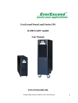
Installation and Operation
Since the inverter operates at a voltage of 24 Volts and 48 Volts, for maximum eciency the batteries
are connected together to increase its voltage from 12 Volts to 24 and 48 Volts as shown in the diagram
connecting the battery with the battery in the box connecting the positive (+) and negative (-)
cables correctly.
Transforming 12 Volt batteries into 24 Volt batteries
Equipment for measuring
battery temperature.
Equipment for measuring
battery temperature.
Transforming 12 Volt batteries into 48 Volt batteries
Caution: After installation, attach the battery temperature measurement equipment to the front of one of the batteries.
Things to look out for when connecting the batteries
1. Set all the breakers to O prior to connecting the batteries.
2. Connect the cables to the correct battery terminal following the wiring diagram.
3. Do not short-circuit the battery terminals.
4. Check the Voltage of the battery after the connection to make sure if it is the desired 24 Volts
or 48 Volts.

INPUT
220VAC
OUTPUT 1
MAINTAINED
OUTPUT 2
NON-MAINTAINED
L N G L N G L N G
INPUT
220VAC
OUTPUT 1
MAINTAINED
OUTPUT 2
NON-MAINTAINED
L N G L N G L N G
4
Steps for connecting the Input and Output
1. Test the readiness of the output load, for example, check for any short-circuits or if the total wattage
exceeds the acceptable load.
Caution: The Output Line and Neutral circuit should be independent from other circuits otherwise
damage could occur to the inverter.
2. When connecting to the Load Output in the circuit box there will be 2 outputs to choose from, which are
1. Output Maintained. This connection will provide a constant 220Vac 50Hz current. This is suitable for
uses that requires a constant current both during normal conditions and during power outages, for
example, providing power for emergency exit signs without a built-in battery or lights that need to be
constantly on such as lights installed in fire escapes or in parking lots.
2. Output Non-Maintained. This connection will not provide a 220Vac 50Hz during normal conditions.
The connection will only provide power during power outages. This connection is suitable for things
such as emergency illumination lamps.
Caution: For the correct connection the Line should be connected into L, Neutral should be connected to
N and Ground should be connected to G. The cables should be connected securely and no foreign objects
should be in the circuit box that could potentially cause a short-circuit.
Diagram showing how to correctly connect cables to the output terminal
3. Connect the Input cables to the Input 220VAC terminal inside the green frame inside the circuit box.
The Line cable should be connected to the L terminal, the Neutral cable to the N terminal and the
Ground cable to the G terminal. The cables should be connected securely and no foreign objects should
be in the circuit box that could potentially cause a short-circuit.
Figure showing how to correctly connect cables to the input terminal

DC.Battery
DC.Battery
AC. Input AC. Output AC. Output
Non - MaintainedMaintained
AC. Input AC. Output AC. Output
Non - MaintainedMaintained
AC.VOLTMETER
DC.VOLTMETER
LED DC.Input
LED Operate
24
220
5
Locations of the Breaker DC. Battery, Breaker AC. Input, Breaker AC. Output
Installation and Operation
1. Set the Breaker DC. Battery to On (shown in the red marking), the inverter will start operation but will
not yet provide power to the Output since the Breaker AC. Output is still o. The indicators at the front
of the unit should, however, indicate the following.
Figure showing the indications at the front of the unit
Shows the current level at the Input to be about 220VAC.
Shows a battery Voltage at 24 or 48 Volts.
The indicator showing that the battery has been connected
to the unit should be on.
The indicator showing that the inverter is operational should
be on.
Caution: The DC Voltage Meter will change according to the Voltage of the battery being
used, for example, 24 Volts or 48 Volts.

AC.VOLTMETER
DC.VOLTMETER
LED DC.Input
LED Operate
24
220
AC. Input AC. Output AC. Output
Non - MaintainedMaintained
DC.Battery
6
Caution: The DC Voltage Meter will change according to the Voltage of the battery being
used, for example, 24 Volts or 48 Volts.
2. Set the Breaker AC.Output to ON (shown in the red marking), the unit should now be providing
power to the load.
Figure showing the indications at the front of the unit
Shows the current level at the Input to be about 220VAC.
Shows a battery Voltage at 24 or 48 Volts.
The indicator showing that the battery has been connected to
the unit should be on.
The indicator showing that the inverter is operational
should be on.

AC.VOLTMETER
DC.VOLTMETER
LED AC.Input
LED DC.Input
LED Charging
24
220
AC. Input AC. Output AC. Output
Non - MaintainedMaintained
DC.Battery
7
Caution: The DC Voltage Meter will change according to the Voltage of the battery being
used, for example, 24 Volts or 48 Volts.
Figure showing the indications at the front of the unit
3. Test to see if the overall current level and load stability is at a normal level.
4. Set the Breaker AC.Input to ON (shown in the red marking), after about 5 seconds the unit should stop
using the inverter and use the main power supply to provide power instead.
Shows the current level at the Output to be about 220VAC.
Shows a battery Voltage at 24VDC or 48 VDC.
The indicator showing that the unit is receiving a 220VAC
current should be on.
The indicator showing that the battery has been connected to
the unit should be on.
The indicator showing that the battery is charging should be on.
If the battery is full, however, the indicator will be o.
5. The unit will be in Standby mode ready to provide emergency power during power outages.

AC.VOLTMETER
DC.VOLTMETER
LED AC.Input
LED DC.Input
LED Charging
LED Testing
24
220
AC. Input AC. Output AC. Output
Non - MaintainedMaintained
DC.Battery
8
Caution: The DC Voltage Meter will change according to the Voltage of the battery being
used, for example, 24 Volts or 48 Volts.
Testing the unit’s operability
1. To test the unit, the user can set the Circuit Breaker AC Input 220VAC to OFF (shown in the red
markings), the unit should start providing backup power to the emergency lights immediately.
2. To stop the test, the user can set the Circuit Breaker AC Input 220 VAC back to ON. The inverter should
stop operating and the unit should return to standby mode.
3. The unit has a built-in self-testing system that will perform 30 minutes self-tests every 30 days.
This self-test system should start working once a current from a battery or AC. Input is provided to
the unit.
Figure showing the indications at the front of the unit
Shows the current level at the Input to be about 220VAC.
Shows a battery Voltage at 24 or 48 Volts.
The indicator showing that the unit is receiving a 220VAC
current should be on.
The indicator showing that the battery has been connected
to the unit should be on.
The indicator showing that the battery is charging should be on.
If the battery is full, however, the indicator will be o.
The indicator showing that the unit automatically testing itself.

AC.VOLTMETER
DC.VOLTMETER
LED AC.Input
LED DC.Input
LED Battery Fail
24
220
24
220
9
Caution: The DC Voltage Meter will change according to the Voltage of the battery being
used, for example, 24 Volts or 48 Volts.
Figure showing the indications at the front of the unit
Figure showing the indications at the front of the unit
4. If during the self-tests the battery is found to be faulty and cannot hold a charge or less charge that
normal the unit will show a “Battery Fail” warning.
5. If the battery charging circuit is found to be faulty, taking longer than 24 hours to charge the battery,
the unit will show a “Charging Fail” warning.
Shows the current level at the Input to be about 220VAC.
Shows a battery Voltage at 24 or 48 Volts.
The indicator showing that the unit is receiving a 220VAC
current should be on.
The indicator showing that the battery has been connected to
the unit should be on.
The indicator showing that the battery can not provide an
electrical charge.
To cancel the Battery Fail notification command, turn
o and on Circuit Breaker “DC.Battery” once.
AC.VOLTMETER
DC.VOLTMETER
LED AC.Input
LED DC.Input
LED Charging Fail
Caution: The DC Voltage Meter will change according to the Voltage of the battery being
used, for example, 24 Volts or 48 Volts.
Shows the current level at the Input to be about 220VAC.
Shows a battery Voltage at 24 or 48 Volts.
The indicator showing that the unit is receiving a 220VAC
current should be on.
The indicator showing that the battery has been connected to
the unit should be on.
The indicator showing that the battery has charged fail.
To cancel the Battery Fail notification command, turn
o and on Circuit Breaker “DC.Battery” once.

10
Maintenance
1. Keep ventilation fan of the unit clean.
2. The unit has an Automatic testing system, automatically enabling 30 minute test every 30 days.
If your unit does not have a self-test system you should manually test the unit once a month for
30 minutes to make sure the unit is fully operational and to help extend the life of the battery.
Initial Trouble Shooting
Problem
Cause What to do
- 220 VAC light not getting
to the unit.
- The power socket might not have
any power.
- Circuit Breaker AC. Input is in the
OFF status.
- Check to make sure that the power socket
of the home or building is providing
a 220 VAC current.
- Check to make sure that theCircuit Breaker
AC. Input is in the ON position.
- The Backup power supply of the
unit has failed.
- Circuit Breaker DC. Battery is in the
OFF status.
- Circuit Breaker AC. Output is in the
OFF status.
- Check to make sure that the Circuit
Breaker DC. Battery is in the ON position.
- Check to make sure that the Circuit
Breaker AC. Output is in the ON position.
- Emergency light only turns on
for a short time after the power
went out.
- The battery is not fully charged.
- The battery has degraded.
- Fully charge the battery.
- Contact customer service to replace
the battery.
Important Note on Using the Unit
1. Please read the manual carefully before installation and operation
2. Installation area should be good ventilation.
3. Do not connect the battery in reverse polarity.
4. Check the power load before installing the unit.
5. Do not use with the power load when it is in an unstable condition.
6. The power load must be an emergency light only. Do not use with the other power load that is not
approved by the manufacturer.
7. The unit should be stored in temperatures under 25 Degree Celsius and the battery should be charged
every 1 month to maintain its operational life.

11
1. The product will only be under warranty if the customer fills in the “warranty card” and return the
“return part” to the company within 7 days of purchasing the product. If this is not done within the
specified time, then the warranty will be considered void.
2. The warranty only covers the unit’s internal parts for the duration specified by the company counting
from the date of purchase.
3. Please show the warranty card every time when contacting our service department or the dealer you
purchased the unit from.
4. The warranty will be considered void in the following cases.
The unit has been used outside of its intended use specified in the manual.
The unit has been used with equipment that does not meet the specifications specified within the
manual.
The unit has been damaged from impact, for example parts are dented, scratched missing or distorted.
The unit has been modified or repaired by people not ocially certified by our company.
The Sticker Warranty Void has been removed or torn.
The unit is damaged from negligence or incompetent use, for example, the battery is swollen, the batter
has been overcharged, the battery has been damaged from quick charging, the battery has been
short-circuited, the battery’s charged has been completely drained.
The unit has been stored improperly, for example, it was exposed to moisture causing rust and damage
to the internal circuitry.
Damaged was caused by a malfunction in the AC power supply.
Damage from natural disaster such as fire, moisture, submersion in liquids, chemical damage or from
unavoidable circumstances.
Damage from animals or insects.
Note : Please read the manual carefully before installation and operation to understand
how to properly operate the unit.
For any further questions about your product
please feel free to contact SUNNY’s customer
service department.
Tel. (+66) 02-948-4450-2
E-mail: ser[email protected]
IsOn Import-Export Co., Ltd.
2915-2917 Ladprao Road, Klongjan,
Bangkapi, Bangkok 10240
Terms for Warranty and Service
/