Page is loading ...

TAILGATE SPREADER VARIABLE SPEED (PWM) CAB CONTROL
INSTALLATION INSTRUCTIONS
NOTE: The cab control can be top or bottom
mounted using the supplied mounting bracket or
an existing snowplow control bracket.
1. Locate a convenient position in the cab to mount
the control that will not interfere with other
equipment and will avoid unintentional starting of
the spreader.
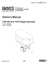
2. Attach the mounting bracket to the vehicle with
three #10-24 x 3/8" tapping screws, #10 spring
lock washers and #10-24 hex nuts as shown.
3. Place the control with a 1/4" nylon washer on each
side into the mounting bracket and secure with the
1/4-20 x 3/8" machine screws and flat washers
through the nut inside the slot on each side.
Top View
White
Red
WARNING
Do not install this product in deployment path
of an air bag. Refer to vehicle manufacturer's
manual for air bag deployment area(s).
Mounting Surface
PWM
Control
Mounting
Bracket
4. Plug the 2-way molded connector from the vehicle
wiring harness into the matching connector
extending from the rear of the cab control.
5. The red and white connectors on the ends of the
two red 8-gauge wires are interlocking. Lock the
connectors together.
6. Connect the interlocked connectors from Step 5
to matching connectors located on the back of the
control. Match red with red, and white with white.
Lit. No. 80325, Rev. 02 1 June 1, 2005

The company reserves the right under its product improvement policy to change construction or design details and furnish equipment when so
altered without reference to illustrations or specifications used. Do not exceed vehicle ratings with a spreader. The company offers a limited
warranty for all spreaders. See separately printed page for this important information.
Lit. No. 80325, Rev. 02 Printed in USA June 1, 2005
TAILGATE SPREADER VARIABLE SPEED (PWM) CAB CONTROL
OPERATING INSTRUCTIONS
Starting and Stopping the Motor
1. To start the spreader motor, press the START/
BLAST button and release. Both the START/
BLAST and OFF buttons will be backlit when the
motor is running. The spreader will operate at the
speed selected on the speed dial.
2. Press the OFF button to stop the motor. The OFF
button operates as emergency stop when required.
NOTE: The truck ignition must be on to start the
spreader.
NOTE: If the truck ignition is turned off while the
spreader is running, the motor will stop.
Adjusting the Spinner Speed
The speed setting can be adjusted when the spreader
is either on or off.
1. Turn the speed dial clockwise. The speed will
increase as the number of green LED's illuminated
on the speed dial increase.
2. Turning the speed dial counterclockwise will
decrease the speed.
Speed DialOff Button (Emergency
stop when required.)
On/Maximum
Speed Button
Diagnostic
Indicator Light
WARNING
Before starting the spreader, the driver shall
verify all bystanders are a minimum of 25 feet
away from operating spreader.
Blast/Maximum Speed
1. Press and hold the START/BLAST button as long
as maximum speed is needed.
2. Release the button when maximum speed is no
longer needed. The control automatically returns
to the ON position and the speed shown on the
speed dial.
NOTE: When blast is used, the speed dial does
not move to the maximum speed setting, but
remains at the preset speed.
Diagnostic Indicator Light
The diagnostic indicator light located to the right of the
START/BLAST button remains dark unless a problem
with the motor or wiring is detected. The light will flash
a number of flashes in a row, pause, then repeat.
Count the flashes to determine the nature of the
malfunction and refer to the diagnostic chart below.
NOTE: Always place the cover on the hopper to
prevent moisture buildup. Do not let the spreader sit
idle with material in the hopper for an extended
period of time. This can cause the material to
compact and reduce or stop the flow of material.
# of
Flashes Problem Possible Causes
0 No Fault –
2 No Power Battery fuse is blown, or battery
cable is disconnected or faulty.
3 No Motor Motor is disconnected.
4 No Ground Spreader harness ground is
disconnected or faulty.
5 Overheated Motor off due to controller overheat,
possibly due to frozen or jammed
spreader.
6 Excess
Current
Over 35A for more than 1-2 seconds.
(Higher overloads are allowed for
shorter periods of time.)
/