SnowEx V-Maxx G2 VX-6010 Installation Instructions Manual
- Type
- Installation Instructions Manual

October 1, 2018
Lit. No. 70472, Rev. 02
V-Maxx™ G2 Hopper Spreader
VX-6010
Installation Instructions
CAUTION
Read this document before installing or
operating the spreader.
A DIVISION OF DOUGLAS DYNAMICS, LLC

Lit. No. 70472, Rev. 02 2 October 1, 2018
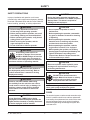
SAFETY DEFINITIONS
NOTE: Indicates a situation or action that can lead
to damage to your spreader and vehicle or other
property. Other useful information can also be
described.
SAFETY
WARNING/CAUTION LABELS
Become familiar with the warning and caution labels
on the spreader.
NOTE: If labels are missing or cannot be read, see
your sales outlet.
CAUTION
Indicates a potentially hazardous situation
that, if not avoided, may result in minor or
moderate injury. It may also be used to alert
against unsafe practices.
WARNING
Indicates a potentially hazardous situation
that, if not avoided, could result in death or
serious personal injury.
• Shut off control and unplug spreader before servicing.
ROTATING AUGER CAN CAUSE
SERIOUS INJURY OR DEATH
• Keep arms, hands, and loose clothing away from auger.
D6335
• DO NOT EXCEED GVWR OF VEHICLE
• DO NOT OVERLOAD SPREADER
• LOAD SPREADER EVENLY D6546
• Read Owner’s Manual for Installation Instructions.
• Secure spreader to truck with ratchet straps.
• Anchor spreader securely to truck body with bolt kit provided to prevent
slipping or sliding.
• Routinely check straps and handware to make sure they are secure.
D6548
ROTATING PARTS AND FLYING OB-
JECTS CAN CAUSE INJURY OR DEATH
• Keep hands, arms, feet and loose clothing away
• Shut o power ans stop engine before servicing
• Read owners manual before operating.
• Keep bystanders at least 60 ft away.
D6544

Lit. No. 70472, Rev. 02 3 October 1, 2018
SAFETY
• Shut off control and unplug spreader before servicing.
ROTATING AUGER CAN CAUSE
SERIOUS INJURY OR DEATH
• Keep arms, hands, and loose clothing away from auger.
D6335
ROTATING PARTS CAN CAUSE
SERIOUS INJURY OR DEATH
• ALWAYS DISCONNECT POWER
WHEN NOT IN USE
ROTATING PARTS CAN CAUSE
SERIOUS INJURY OR DEATH
• ALWAYS DISCONNECT POWER
WHEN NOT IN USE
SERIAL NUMBER LABEL
Code Defi nition
YY 2-Digit Year
MM 2-Digit Month
DD 2-Digit Day
LL 2-Digit Location Code
XXXX 4-Digit Sequential Number
ZZZZZ 5–7-Digit Assembly Part Number
TrynEx International, LLC
531 Ajax Drive
Madison Heights, MI 48071
YYMMDDLLXXXXZZZZZ
VX-6010 6.0 CU YD AUGER POLY HOPPER

Lit. No. 70472, Rev. 02 4 October 1, 2018
WARNING
Vehicles <10,000 lb GVWR: Obstructing
the visibility from the vehicle's rear camera
could result in serious injury or damage. An
auxiliary camera system shall be installed
if the vehicle's rear camera is removed or
blocked.
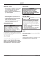
SAFETY
SAFETY PRECAUTIONS
Improper installation and operation could cause
personal injury and/or equipment and property damage.
Read and understand labels and this Owner's Manual
before installing, operating, or making adjustments.
WARNING
• Driver to keep bystanders minimum of
25 feet away from operating spreader.
• Before working with the spreader, secure all
loose-fi tting clothing and unrestrained hair.
• Before operating the spreader, verify that all
safety guards are in place.
• Before servicing the spreader, wait for
auger and spinner to stop.
• Do not climb into or ride on spreader.
WARNING
Overloading could result in an
accident or damage. Do not exceed
GVWR or GAWR ratings as found on
the driver-side door cornerpost of
the vehicle. See Loading section to determine
maximum volumes of spreading material.
WARNING
Do not install the control for this product in
the deployment path of an air bag. Refer to
vehicle manufacturer's manual for air bag
deployment area(s).
CAUTION
During the hopper spreader installation we
recommend the addition of an OSHA compliant
Backup Alarm. This alarm is required for
OSHA governed employers.
CAUTION
• Do not operate a spreader in need of
maintenance.
• Before operating the spreader, reassemble
any parts or hardware removed for cleaning
or adjusting.
• Before operating the spreader, remove
materials such as cleaning rags, brushes,
and hand tools from the spreader.
• Before operating the spreader, read the
engine owner's manual, if so equipped.
• While operating the spreader, use auxiliary
warning lights, except when prohibited by law.
• Tighten all fasteners according to the
Torque Chart. Refer to Torque Chart for the
recommended torque values.
CAUTION
Disconnect electric and/or hydraulic power
and tag out if required before servicing or
performing maintenance.
CAUTION
DO NOT leave unused material in
hopper. Material can freeze or solidify,
causing unit to not work properly.
Empty and clean after each use.
NOTE: Lubricate grease fi ttings after each use.
Use a good quality multipurpose grease.
FUSES
The electrical system contains several automotive-style
fuses. If a problem should occur and fuse replacement
is necessary, the replacement fuse must be of the same
type and amperage rating as the original. Installing a
fuse with a higher rating can damage the system and
could start a fi re.
CAUTION
If rear directional, CHMSL light, or brake
stoplights are obstructed by the spreader, the
lights shall be relocated, or auxiliary directional
or brake stoplights shall be installed.

Lit. No. 70472, Rev. 02 5 October 1, 2018
SAFETY
VENTILATION
BATTERY SAFETY
NOISE
Airborne noise emission during use is below 70 dB(A)
for the spreader operator.
VIBRATION
Operating spreader vibration does not exceed 2.5 m/s2
to the hand-arm or 0.5 m/s2 to the whole body.
PERSONAL SAFETY
• Remove ignition key and put the vehicle in PARK
or in gear to prevent others from starting the
vehicle during installation or service.
• Wear only snug-fi tting clothing while working on
your vehicle or spreader.
• Do not wear jewelry or a necktie, and secure long
hair.
• Wear safety goggles to protect your eyes from
battery acid, gasoline, dirt, and dust.
• Avoid touching hot surfaces such as the engine,
radiator, hoses, and exhaust pipes.
• Always have a fi re extinguisher rated BC handy,
for fl ammable liquids and electrical fi res.
FIRE AND EXPLOSION
Be careful when using gasoline. Do not use gasoline
to clean parts. Store only in approved containers away
from sources of heat or fl ame.
CELL PHONES
A driver's fi rst responsibility is the safe operation of
the vehicle. The most important thing you can do
to prevent a crash is to avoid distractions and pay
attention to the road. Wait until it is safe to operate
Mobile Communication Equipment such as cell phones,
text messaging devices, pagers, or two-way radios.
WARNING
Gasoline is highly fl ammable and gasoline
vapor is explosive. Never smoke while
working on vehicle. Keep all open fl ames
away from gasoline tank and lines. Wipe up
any spilled gasoline immediately.
CAUTION
Batteries normally produce explosive gases
which can cause personal injury. Therefore,
do not allow fl ames, sparks, or lit tobacco
to come near the battery. When charging or
working near a battery, always cover your
face and protect your eyes, and also provide
ventilation.
• Batteries contain sulfuric acid, which burns
skin, eyes, and clothing.
• Disconnect the battery before removing or
replacing any electrical components.
WARNING
Vehicle exhaust contains lethal fumes.
Breathing these fumes, even in low
concentrations, can cause death. Never
operate a vehicle in an enclosed area without
venting exhaust to the outside.

Lit. No. 70472, Rev. 02 6 October 1, 2018
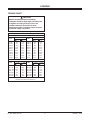
TORQUE CHART
1/4-20 109 154
1/4-28 121 171
5/16-18 150 212
5/16-24 170 240
3/8-16 269 376
3/8-24 297 420
7/16-14 429 606
7/16 -20
9/16-12
9/16-18
5/8-11
5/8-18
3/4-10
3/4-16
7/8-9
7/8-14 474 669
644 9091-8
1-12 704 995
1/2-13
1/2-20
11.9
13.7
24.6
27.3
43.6
26.9
53.3
93
148
49.4
69.8
77.9
106.4
120.0
8.4
9.7
17.4
19.2
30.8
35.0
49.4
55.2
75.3
85.0
M6 x 1.00
M12 x 1.75
M8 x 1.25
M14 x 2.00
M10 x 1.50
M27 x 3.00
M22 x 2.50
M30 x 3.50
M24 x 3.00
M20 x 2.5011.1
19.5
38.5
67
107
7.7
613
778
1139
1545
450
428
562
796
1117
M33 x 3.50
M36 x 4.00
2101
2701
1468
1952
325
M16 x 2.00 231
167
M18 x 2.50 318222
Recommended Fastener Torque Chart
Size Size
Torque (f t-lb)
Grade
5
Grade
8
Metric Fasteners Class 8.8 and 10.9
These torque values apply to fasteners
except those noted in the instructions.
Torque (f t-lb)
Grade
5
Grade
8
Size Size
Torque (f t-lb)
Class
8.8
Class
10.9
Torque (f t-lb)
Class
8.8
Class
10.9
Inch Fasteners Grade 5 and Grade 8
CAUTION
Read instructions before assembling.
Fasteners should be fi nger tight until instructed
to tighten according to torque chart. Use
standard methods and practices when
attaching spreader, including proper personal
protective safety equipment.
LOADING

Lit. No. 70472, Rev. 02 7 October 1, 2018
SPREADER SPECIFICATIONS
These Installation Instructions cover vehicles that
have been recommended for carrying the hopper
spreader. Please see your local dealer for proper
vehicle applications.
CERTIFICATION
WARNING
Overloading could result in an accident or
damage. Do not exceed GVWR or GAWR as
found on the driver-side cornerpost of vehicle.
WARNING
New untitled vehicle installation of a spreader
requires National Highway Traffi c Safety
Administration altered vehicle certifi cation
labeling. Installer to verify that struck load of
snow or ice control material does not exceed
GVWR or GAWR rating label and complies
with FMVSS.
CAUTION
Read and adhere to manufacturer's
ice-control material package
labeling, including Material Safety
Data Sheet requirements.
CAUTION
Never use wet materials or materials with
foreign debris with any of these spreaders.
These units are designed to handle dry, clean,
free-fl owing material.
MATERIAL WEIGHTS
Density
Material (lb/ft3)(lb/yd
3)(kg/m
3)
Salt 80 2160 1282
Sand 100 2700 1602
Material densities are approximate and are based on dry,
loose material. It is the responsibility of the operator to
know the weight of the material to be spread and the vehicle
carrying capacity.
LOADING
Hopper
Model
Overall
Length
(in)
Bed
Length
(in)
Empty
Weight
(lb)
Overall
Width
(in)
Bed
Height
(in)
Capacity
Struck
(yd3)
VX-6010 155 122 1100 66 55 6.0

Lit. No. 70472, Rev. 02 8 October 1, 2018
NOTE: Periodically throughout the snow and ice
control season, verify that mounting devices
are secure.
Remove the pallet, open the top screen, and remove
the parts boxes.
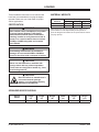
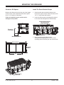
INSTALL HOPPER IN VEHICLE BED
1. Remove the vehicle tailgate or rear racks.
2. Use slings or chains to lift the spreader by the four
large round holes on the top of the diagonal corner
rails. Move the spreader into the vehicle bed, allowing
room for the rear stop bracket to be installed.
3. Assemble the rear stop bracket onto the auger
extension frame using two 1/2" x 1" cap screws,
1/2" fl at washers, and 1/2" locknuts. Use the
rearmost frame holes.
4. Remove the spinner harness plug from the tab
on the frame. Assemble the spinner harness plug
bracket to the tab on the frame, as shown, using
two #10 x 1-1/4" pan head screws and
#10 locknuts.
5. Feed the spinner harness plug through the slot in
the bracket, and press the fi r tree mount on the
plug into the hole in the bracket.
6. Slide the spreader forward until the stop bracket
contacts the rear of the truck body. If the spreader
frame hits the front of the truck bed fi rst, relocate
the stop bracket on the frame so that it contacts
the rear of the truck bed.
7. Center the spreader side-to-side on the truck bed.
The spreader must be centered for the safety of
the vehicle, the driver, and those nearby.
MOUNTING THE SPREADER
Rear Stop Bracket
Mounting Holes Frame Mounting
Holes (three per side)
Round Holes
(two per side)
CAUTION
Before lifting, verify that the hopper is empty
of material. The lifting device must be able to
support the spreader's weight as shown in
the spreader specifi cations table.
B
Auger
Extension
Frame
Rear Stop
Bracket
1/2" x 1" Cap Screw,
1/2" Washer, 1/2" Locknut;
Both Sides
Spinner
Harness Plug
Bracket
#10 x 1-1/4" Pan
Head Screw,
#10 Locknut
Tab
Spinner
Harness Plug
(wires not shown)

Lit. No. 70472, Rev. 02 9 October 1, 2018
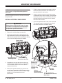
1. Using the six mounting holes in the spreader side
rails and two outer holes in the rear stop bracket
as a template, mark mounting hole positions on
the vehicle bed. Drill 9/16" holes for the frame
bolts.
NOTE: Pay special attention when drilling or
clamping dissimilar metals to aluminum bodies.
Galvanic corrosion can occur if not handled
properly. Contact vehicle manufacturer for
recommended attachment practices.
MOUNTING THE SPREADER
WARNING
Spreader shall be bolted to vehicle frame.
Do not rely on the tie-down chains or straps
alone to hold spreader in vehicle.
CAUTION
Before drilling holes, check to be sure that no
vehicle wiring or other components could be
damaged.
Rear Stop Bracket
Mounting Holes Frame Mounting
Holes (three per side)
2. Secure the spreader to the vehicle bed using eight
1/2" x 1-1/2" cap screws with 1/2" fl at washers and
1/2" locknuts on the bottom.
If the mounting holes are not directly over the
vehicle box supports, the vehicle bed must
be braced to the frame to prevent buckling or
deforming the vehicle bed.
3. Close and secure the top screen.

Lit. No. 70472, Rev. 02 10 October 1, 2018
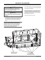
Install Tie-Down Ratchet Straps
1. Attach ratchet strap mounting brackets to the
holes in the upper corners of the side frames with
1/2" x 1" cap screws and locknuts.
2. Hook the ratchet strap hooks diagonally outward
to the truck bed and tighten the ratchet straps.
3. Move the spinner assembly from the
storage/dump shipping position to the normal
operating position following the instructions below.
MOUNTING THE SPREADER
Ratchet Strap Bracket
Mounting Holes
(two per side)
Construct Sill Spacer
Measure the distance from the front end of the hopper
sill to the front of the vehicle bed and make a spacer
from 2" x 8" lumber to fi t that area.
Failure to install this spacer could result in
damage to the spreader.
Frame Spacer
Built to Fit
Front of
Truck Bed
Measure distance.
18"
Fit to vehicle.
Measured
Distance

Lit. No. 70472, Rev. 02 11 October 1, 2018
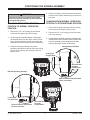
CHANGING FROM STORAGE/DUMP
POSITION TO NORMAL OPERATING
POSITION
1. Remove the 1/4" x 24" locking pin and hairpin
cotter from the upper hole in the housing.
2. Lift the spinner assembly upward to disengage
the shoulder bolts from the upper notches on the
frame. Pivot the assembly down and engage the
shoulder bolts into the lower notches on the frame.
3. Install the locking pin through the spinner
assembly and the frame through the lower locking
pin hole in the housing. Secure the pin with the
hairpin cotter.
POSITIONING THE SPINNER ASSEMBLY
4. Remove the plug covers and connect the spinner
harness to the spinner harness plug on the rear of
the frame.
CHANGING FROM NORMAL OPERATING
POSITION TO STORAGE/DUMP POSITION
1. Disconnect the spinner harness from the spinner
harness plug, and install the plug covers.
2. Remove the 1/2" x 24" locking pin from the lower
hole in the housing.
3. Lift the spinner assembly upward to disengage the
shoulder bolts from the lower notches on the frame,
pivot the assembly up and engage the shoulder
bolts into the upper notches on the frame.
WARNING
The spinner harness must be disconnected
before the spinner assembly is moved into the
storage/dump position.
Storage/Dump Position
Spinner Harness Disconnected
(wires not shown)
Locking Pin
in Upper Hole
Shoulder Bolt
in Upper
Frame Notch
Normal Operating Position
Locking Pin
in Lower Hole
Shoulder Bolt
in Lower
Frame Notch
Spinner Harness Connected
(wires not shown)

Lit. No. 70472, Rev. 02 12 October 1, 2018
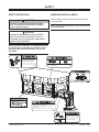
WIRING AND HARNESS INSTRUCTIONS
Vehicle Battery Cable Installation
1. Before beginning this installation, remove the
battery cables from the vehicle battery.
2. Using the 1/4" x 3/4" cap screws, 1/4" fl at washers,
and 1/4" locknuts, mount the fuse holder near
the vehicle battery so that the 22" battery cable
can be installed from the POSITIVE (+) battery
terminal to the fuse holder. Install the fuse into the
fuse holder and hand tighten the nuts.
3. Attach one end of the 22" battery cable to the fuse
holder so that the ring terminal is on top of the
fuse; replace the lock washer and nut.
4. Lay out a path for routing the vehicle battery cable
from the rear of the vehicle bed to the vehicle
battery. Make sure that the path avoids any hot,
sharp, or moving parts of the vehicle. Routing will
vary from vehicle to vehicle.
5. Route the vehicle battery cable as laid out in Step 4.
6. Using cable ties, secure the battery cable to
the vehicle. Verify that the harness cannot drop
onto the road when it is disconnected from the
spreader.
7. Attach the vehicle battery cable red wire to the
other fuse holder stud so that the ring terminal is
on top of the fuse; replace the lock washer and
nut.
8. Torque the fuse holder nuts to 106–159 in-lb and
snap the fuse holder cover into place.
9. Attach the other end of the 22" battery cable to
the POSITIVE (+) battery post.
10. Attach the vehicle battery cable black wire to the
NEGATIVE (–) battery terminal.
WIRING INSTRUCTIONS
Spreaders are shipped from the factory with the
spreader harness wired to the motor and spreader
module.
To properly wire the hopper spreader, follow this
recommended installation sequence:
1. Install the vehicle battery cable and control
harness included with the spreader, following the
steps given below.
2. Install the cab control as described under "Cab
Control Installation."
NOTE: Use dielectric grease on all electrical
connections.

Lit. No. 70472, Rev. 02 13 October 1, 2018
WIRING AND HARNESS INSTRUCTIONS
5. Insert a rubber grommet into the hole.
6. Route the harness as laid out in Step 2.
7. Secure the vehicle control harness to the vehicle.
8. Attach the red wire to a switched accessory circuit.
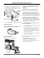
Cab Control Installation
1. Confi rm that the chosen cab control mounting
position will not interfere with other equipment or
allow unintentional starting of the spreader.
2. Install the vehicle side of the mounting bracket
using three #10 x 3/8" Phillips head tapping
screws.
3. Install the control side of the bracket to the control
using four #8 x 3/8" Phillips head machine screws.
Vehicle Control Harness Installation
1. Plug the vehicle harness into the spreader harness.
2. Lay out a path for routing the vehicle control
harness from its attachment point on the vehicle
battery cable into the cab of the vehicle. Make sure
that the path avoids any hot, sharp, or moving parts
of the vehicle. Routing will vary from vehicle to
vehicle.
3. Choose a cab control mounting location that can
be reached by the harness. The location must
be within easy reach of the vehicle operator
without restricting access to vehicle controls or
instrumentation.
Do not mount the control in areas prohibited
by the vehicle manufacturer for reasons of
crashworthiness. See the vehicle's body builder's
book, owner's manual, or service manual for
details. The shaded portions in the illustration
below show the most commonly restricted areas.
4. Drill a 5/8" hole in the fi re wall so that the vehicle
control harness can reach the desired cab control
location.
CAUTION
Before drilling any holes, check both sides
of the material for any wires, fuel lines, fuel
tanks, etc., that may be damaged by drilling.
CAUTION
Do not alter, modify, or install additional
components in shaded areas shown below.
Failure to comply may interfere with airbag
deployment or cause injury to operator in an
accident.
Control Side
(Control not shown.)
Vehicle Side
#10 x 3/8"
Tapping
Screw
#8 x 3/8"
Machine
Screw

Lit. No. 70472, Rev. 02 14 October 1, 2018
4. Install the control side of the bracket to the vehicle
side using 1/4" x 1/2" Phillips head machine
screws, 1/4" nylon shoulder washers, 1/4" lock
washers, and 1/4" locknuts.
5. Plug the vehicle control harness into the cab control.
Harness Plug Cover
Install the supplied harness plug cover by slipping the
loop end of the cover over the harness plug.
Spreader Cable Boot
Install the cable boot onto the bracket.
WIRING AND HARNESS INSTRUCTIONS
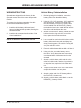
CENTER HIGH-MOUNTED STOPLIGHT
(CHMSL)
An LED center high-mounted stoplight is standard
equipment on all V-Maxx™ hopper spreaders.
The orange wire from the spreader vehicle harness
is for the CHMSL. Splice the orange wire into an
existing CHMSL circuit wire tap. Location of the tap
varies according to specifi c vehicle model, and may be
located either in the cab or in the rear of the vehicle.
Always use the tap provided by the OEM.
DO NOT splice the orange wire into the wire coming
off the stoplight switch by the brake pedal. Splicing at
the stoplight switch may affect transmission shifting,
cruise control, or other vehicle functions.
For vehicles with a tap along the frame rail or at
the rear cross member:
1. Cut the tape holding the orange wire where it exits
the convoluted tubing.
2. Pull out the orange wire to the location where the
vehicle CHMSL tap is located. Cut a small
V notch in the tubing for the wire to exit. Pull the
wire through the V notch and tape the tubing on
each side of the exit point.
3. Trim any excess length from the orange wire and
splice into the vehicle tap.
Coil and cable-tie the brown wire away from any hot,
sharp, or moving parts.
ACCESSORY LED WORK LIGHT
To install the accessory LED work light, follow the
instructions included with the kit.
(Control not shown.)
1/4" Shoulde
r
Washer
1/4" Lock
Washer
1/4" Locknut
1/4" x 1/2"
Machine Screw
Cable Boot

Lit. No. 70472, Rev. 02 15 October 1, 2018
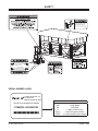
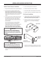
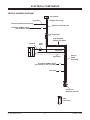
ELECTRICAL COMPONENTS
+
_
Battery
Cab Control
4-Way Connector
Connectors
18 ga Shielded
Twisted-Pair Cable
4 ga Red
18 ga Black
4 ga Black
Connect to
Spreader Harness
To Vehicle CHMSL Signal
(tap located in cab)
To Vehicle CHMSL Signal
(tap located in rear of vehicle)
Not Used
100A
Fuse
6 ga Red
18 ga Red
To Vehicle Switched Accessory
BRN
ORN
ORN
8-Pin
Connector
Vehicle Control Harness
Vehicle
Cable
Assembly
VEHICLE HARNESS DIAGRAM

Lit. No. 70472, Rev. 02 16 October 1, 2018
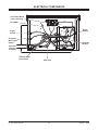
Auger
Switch
Spreader
Harness
Assembly
ACC Power Block
(cover removed)
Accessory
Work Light
Switch
Auger
Switch
Spreader
Module
POSITIVE (+)
NEGATIVE (–)
To CHMSL
Vibrator Relay
Fuse Holder ACC Taps
FEEDPN
BAT
SPIN
RED
BLK
GND
BLK
ORN
B
GRY
BLK
RED
BLK
BLUE
WHT
RED
BLK
BLK
BLK
ELECTRICAL COMPONENTS

Lit. No. 70472, Rev. 02 17 October 1, 2018
FINAL ADJUSTMENTS
FINAL CHECKLIST
Verify that the auger and spinner turn freely.
Verify that dielectric grease is applied to all
electrical connections.
Verify that wire harnesses and battery cables are
properly secured away from hot or moving parts.
Verify that the vehicle battery cable has suffi cient
ground clearance when the spreader is removed
from the vehicle.

Lit. No. 70472, Rev. 02 18 October 1, 2018
A DIVISION OF DOUGLAS DYNAMICS, LLC
TrynEx International, LLC
531 Ajax Drive
Madison Heights, MI 48071-2429
www.snowexproducts.com
Copyright © 2018 Douglas Dynamics, LLC. All rights reserved. This material may not be reproduced or copied, in whole or in part, in
any printed, mechanical, electronic, fi lm, or other distribution and storage media, without the written consent of TrynEx International, LLC.
Authorization to photocopy items for internal or personal use by TrynEx International outlets or spreader owner is granted.
TrynEx International reserves the right under its product improvement policy to change construction or design details and furnish equipment
when so altered without reference to illustrations or specifi cations used. TrynEx International or the vehicle manufacturer may require or
recommend optional equipment for spreaders. Do not exceed vehicle ratings with a spreader. TrynEx International offers a limited warranty for
all spreaders and accessories. See separately printed page for this important information. The following are registered (®) or unregistered (™)
trademarks of Douglas Dynamics, LLC: SnowEx®, V-Maxx™.
Printed in U.S.A.
-
 1
1
-
 2
2
-
 3
3
-
 4
4
-
 5
5
-
 6
6
-
 7
7
-
 8
8
-
 9
9
-
 10
10
-
 11
11
-
 12
12
-
 13
13
-
 14
14
-
 15
15
-
 16
16
-
 17
17
-
 18
18


SnowEx V-Maxx G2 VX-6010 Installation Instructions Manual
- Type
- Installation Instructions Manual
Ask a question and I''ll find the answer in the document
Finding information in a document is now easier with AI
Related papers
-
 SnowEx V-Maxx G2 VX-2200HO Installation Instructions Manual
-
 SnowEx Bulk Pro SP-1575 Owner's Manual and Installation Instructions
-
 SnowEx SP-1575-1 Owner's manual
-
 SnowEx SR-210 Owner's Manual and Installation Instructions
-
 SnowEx SP-85 Owner's/Operator's Manual
-
 SnowEx SP-85 Owner's Manual and Installation Instructions
-
 SnowEx SP-2200 User manual


Other documents
-
Western Utility Mount Kit #75922 Installation guide
-
-
-
-
-
-
-
-
-