Page is loading ...

3A2797G
EN
Setup - Operation
HFR
™
for NVH
Foam - Cart
Hydraulic, Plural-Component, Fixed-Ratio Proportioner.
For dispensing NVH foam.
For professional use only. Not approved for use in explosive atmospheres or hazardous
locations.
See page 4 for model information and maximum
working pressure.
Patents Pending
Important Safety Instructions
Read all warnings and instructions in this
manual. Save these instructions.
ti19507a

2 3A2797G
Contents
Related Manuals . . . . . . . . . . . . . . . . . . . . . . . . . . . 3
Models . . . . . . . . . . . . . . . . . . . . . . . . . . . . . . . . . . . 4
Accessories . . . . . . . . . . . . . . . . . . . . . . . . . . . . . . . 6
Applicator . . . . . . . . . . . . . . . . . . . . . . . . . . . . . . 6
GX-16 Orifices . . . . . . . . . . . . . . . . . . . . . . . . . . 6
B (Blue) and A (Red) Feed Tanks . . . . . . . . . . . 6
AC Power Pack . . . . . . . . . . . . . . . . . . . . . . . . . . 6
Refill Kits . . . . . . . . . . . . . . . . . . . . . . . . . . . . . . . 6
GX-16 Shutoff Valve Kit . . . . . . . . . . . . . . . . . . . 6
Additional Accessories . . . . . . . . . . . . . . . . . . . . 7
Communications Gateway Module (CGM) . . . . . 7
Bag Filter Kits . . . . . . . . . . . . . . . . . . . . . . . . . . . 7
GX-16 Fitting Kits . . . . . . . . . . . . . . . . . . . . . . . . 7
Warnings . . . . . . . . . . . . . . . . . . . . . . . . . . . . . . . . . 8
Important Two-Component Material Information 11
Isocyanate Conditions . . . . . . . . . . . . . . . . . . . . 11
Material Self-ignition . . . . . . . . . . . . . . . . . . . . . 11
Keep Components A (Red) and B (Blue) Separate
11
Moisture Sensitivity of Isocyanates . . . . . . . . . . 11
Foam Resins with 245 fa Blowing Agents . . . . . 11
Changing Materials . . . . . . . . . . . . . . . . . . . . . . 12
A (Red) and B (Blue) Components . . . . . . . . . . . . 12
Typical Installation . . . . . . . . . . . . . . . . . . . . . . . . 13
Component Identification . . . . . . . . . . . . . . . . . . . 14
HFR Hydraulic Power Pack . . . . . . . . . . . . . . . . 17
Motor Control Module (MCM) . . . . . . . . . . . . . . 18
Advanced Display Module (ADM) . . . . . . . . . . . 20
Fluid Control Module (FCM) . . . . . . . . . . . . . . . 23
Temperature Control Module . . . . . . . . . . . . . . . 24
Setup . . . . . . . . . . . . . . . . . . . . . . . . . . . . . . . . . . . . 28
Startup . . . . . . . . . . . . . . . . . . . . . . . . . . . . . . . . . . 43
Shutdown . . . . . . . . . . . . . . . . . . . . . . . . . . . . . . . . 44
Pressure Relief Procedure . . . . . . . . . . . . . . . . . . 44
Flushing . . . . . . . . . . . . . . . . . . . . . . . . . . . . . . . . . 45
Maintenance . . . . . . . . . . . . . . . . . . . . . . . . . . . . . . 46
Install Upgrade Tokens . . . . . . . . . . . . . . . . . . . 47
IsoGuard Select
™
System . . . . . . . . . . . . . . . . 48
Troubleshooting . . . . . . . . . . . . . . . . . . . . . . . . . . . 49
Light Tower (Optional) . . . . . . . . . . . . . . . . . . . . 49
Appendix A - ADM Icons Overview . . . . . . . . . . . 52
Setup Screen Icons . . . . . . . . . . . . . . . . . . . . . . 52
Run Screen Icons . . . . . . . . . . . . . . . . . . . . . . . 53
Appendix B - ADM Setup Screens Overview . . . 54
Appendix C - ADM Run Screens Overview . . . . . 69
Appendix D - ADM Error Codes . . . . . . . . . . . . . . 75
Appendix E - System Events . . . . . . . . . . . . . . . . 87
Appendix F - USB Operation . . . . . . . . . . . . . . . . . 89
Overview . . . . . . . . . . . . . . . . . . . . . . . . . . . . . . 89
USB Options . . . . . . . . . . . . . . . . . . . . . . . . . . . 89
Download Log Files . . . . . . . . . . . . . . . . . . . . . . 89
Log Files, Folder Structure . . . . . . . . . . . . . . . . 90
Transfer System Settings . . . . . . . . . . . . . . . . . . 92
Update Custom Language . . . . . . . . . . . . . . . . . 93
Technical Data . . . . . . . . . . . . . . . . . . . . . . . . . . . . 95
Motor Control Module Technical Data . . . . . . . . 96
Dimensions . . . . . . . . . . . . . . . . . . . . . . . . . . . . 97
Graco Standard Warranty . . . . . . . . . . . . . . . . . . . 98
Graco Information . . . . . . . . . . . . . . . . . . . . . . . . . 98

Related Manuals
3A2797G 3
Related Manuals
Manuals are available at www.graco.com. Component
manuals below are in English:
System Manuals
313998 HFR Repair-Parts
Power Distribution Box Manual
3A0239 Power Distribution Boxes Instruc-
tions-Parts
Pumpline Manuals
3A0019 Z-Series Chemical Pumps Instruc-
tions-Parts
3A0020 HFR Hydraulic Actuator Instruc-
tions-Parts
Feed System Manuals
3A0238 AC Hydraulic Power Pack Instruc-
tions-Parts
3A0235 Feed Supply Kits
Instructions-Parts
3A0395 Stainless Steel Tank Feed Sys-
tems Instructions-Parts
3A1299 Carbon Steel Tank Feed Systems
Instructions-Parts
3A0237 Heated Hoses and Applicator Kits,
Instructions-Parts
308495
Viscon
®
Heater Kit Manual
Dispense Valve Manuals
313536 GX-16, Operation
Accessory Manuals
3A1149 HFR Discrete Gateway Module
Kits Manual
312864 HFR Communications Gateway
Module Instructions-Parts
3A1936 Agitator Kit
Instructions-Parts
3A1962 Agitator Kit with Heat Blanket
Instructions-Parts
3A1657 HFR Flow Meter Kits
Instructions-Parts
332544 HFR for NVH Prepoly Refresh Kit
Instructions-Parts

Models
4 3A2797G
Models
System
Full Load
Peak Amps
Per Phase*
Voltage
(phase)
Primary
Heater
Watts
A (Red)
Primary
Heater
Watts
B (Blue)
Max Flow
Rate◆
lb/min
(kg/min)
Approximate
Output per
Cycle (A+B)
gal. (liter)
Hydraulic
Pressure
Ratio
Maximum
Fluid Working
Pressure ‡
psi (MPa, bar)
24N569 90 230V (3)
6,000
4,000
18 (8.2) 0.033 (0.125) 1.9:1
2000
(14, 138)
24N570 ★✖ 68 400V (3)
24N571 90 230V (3)
24 (11) 0.045 (0.170) 1.4:1
24N572 ★✖ 68 400V (3)
24N573 90 230V (3)
6,000 17 (7.7) 0.032 (0.121) 3.7:1
24N574 ★✖ 68 400V (3)
24N575 90 230V (3)
4,000 18 (8.2) 0.033 (0.125) 1.9:1
24N576 ★✖ 68 400V (3)
System
Material
Ratio
(A:B)
A (Red)
Pump
Size
B (Blue)
Pump
Size
A (Red)
Orifice
B (Blue)
Orifice
25’ (7.6 m)
Chemical
Hose Bundle
10’ (3 m)
Chemical
Hose Bundle
24N569
24:1 120 5 .061 .011
24J290 24J316
24N570 ★
24N571
16:1 160 10 .057 .014
24N572 ★
24N573
1:1 60 60 .039 .039 24N287 24N289
24N574 ★
24N575
24:1 120 5 .085 .013 24K681
24N576 ★
System
27.5’ (8.4 m)
Hydraulic
Hose Bundle
10’ (3 m)
Hydraulic
Hose Bundle
24N569
24V197 24J177
24N570 ★
24N571
24N572 ★
24N573
24N574 ★
24N575
24N576 ★

Models
3A2797G 5
* Full load amps with all devices operating at maximum capabilities. Fuse requirements at various flow rates and
mix chamber sizes may be less.
◆ Flow rate is independent of frequency 50/60 Hz.
★ approved.
‡ The maximum fluid working pressure for the base machine without hoses is 3000 psi (20.7 MPa, 207 bar). If
hoses rated at less than 3000 psi are installed, the system maximum fluid working pressure becomes the rating of
the hoses. If 2000 psi hoses were purchased and installed by Graco, the working pressure for the machine is
already setup for the lower 2000 psi (13.8 MPa, 138 bar) working pressure by Graco. If the machine was pur-
chased without hoses and aftermarket hoses rated at or above 3000 psi are to be installed, see instruction man-
ual 313998 for the procedure to setup the machine for higher rated hoses. The change in working pressure is
made by changing a rotary switch setting in the Motor Control Module. The minimum pressure rating for hoses is
2000 psi. Do not install hoses with a pressure rating lower than 2000 psi.
✖ See 400 V Power Requirements.
400 V Power Requirements
• 400 V systems are intended for International voltage
requirements. Not for voltage requirements in North
America.
• If a 400 volt configuration is operated in North Amer-
ica, a special transformer rated for 400 V (“Y” con-
figuration (4 wire)) may be required.
• North America mostly employs a 3 wire or Delta
configuration. The two configurations are not inter-
changeable.

Accessories
6 3A2797G
Accessories
Applicator
GX-16 Orifices
B (Blue) and A (Red) Feed Tanks
AC Power Pack
Refill Kits
GX-16 Shutoff Valve Kit
GX-16 Proximity Kit
Part Description
24J187 GX-16, 24:1, Straight, Machine Mount
24K233 GX-16, 24:1, Left, Machine Mount
24K234 GX-16, No Orifice, Left, Machine Mount
24E876 GX-16, No Orifice, Straight, Machine Mount
24E877 GX-16, 24:1, Right, Machine Mount
24E878 GX-16, No Orifice, Right, Machine Mount
Part Description
257701 0.011 in. Orifice
257702 0.013 in. Orifice
24N158 0.014 in. Orifice
257703 0.016 in. Orifice
257704 0.018 in. Orifice
257705 0.020 in. Orifice
257706 0.022 in. Orifice
257707 0.023 in. Orifice
257708 0.024 in. Orifice
257709 0.025 in. Orifice
257710 0.026 in. Orifice
257711 0.028 in. Orifice
257712 0.029 in. Orifice
257713 0.032 in. Orifice
257714 0.035 in. Orifice
257715 0.036 in. Orifice
257716 0.038 in. Orifice
257717 0.039 in. Orifice
257718 0.040 in. Orifice
257719 0.042 in. Orifice
257720 0.043 in. Orifice
257721 0.044 in. Orifice
257722 0.049 in. Orifice
257723 0.052 in. Orifice
24N159 0.057 in. Orifice
257724 0.061 in. Orifice
24K682 0.085 in. Orifice
Part Description
24N594 20 gal. (75 l) Stainless Steel Tank, No Agitation,
Insulation, 3 Level Sensors, A-Side
24N595 20 gal. (75 l) Stainless Steel Tank, No Agitation,
Insulation, 3 Level Sensors, B-Side
24N578 20 gal. (75 l) Carbon Steel Tank, No Agitation, 3
Level Sensors, A-Side
24N597 20 gal. (75 l) Carbon Steel Tank, No Agitation, 3
Level Sensors, B-Side
24N579 2 gal. (8 l) Stainless Steel Tank, No Agitation, 1
Level Sensor, B-Side
Part Description
24J912 230V, AC Power Pack
24J913 400V, AC Power Pack
24E347 Hydraulic Power Pack Level Sensor Kit
24C872 Hydraulic Power Pack Pressure Gauge Kit
24E348 Hydraulic Power Pack Temperature Sensor
124217 Power Pack Accumulator Charging Kit
Part Description
24M418 Low Volume, 2 gal. (7.6 l) tank
24M419 High Volume, 20 gal. (76 l) tank
Part Description
24M596 GX-16 Shutoff Valve Kit
For use with: 24N569, 24N570, 24N571, 24N572,
24N573, 24N574
24M368 GX-16 Shutoff Valve Kit
For use with: 24N575, 24N576
Part Description
24K659 GX-16 Proximity Kit

Accessories
3A2797G 7
Additional Accessories
* Flow meter electronics kit, 24J318, is required for flow meter kit
installation.
Communications Gateway
Module (CGM)
Bag Filter Kits
GX-16 Fitting Kits
The following kit is for Models 24N575 and 24N576 only.
The following kits are for all other Models.
Part Description
24C871 Hydraulic Power Pack Hydraulic Tank Fluid Level
Sensor
24C873 Hydraulic Power Pack Manifold Oil Temperature
Sensor
24F516 IsoGuard Select fluid, 6 quarts
121728 Extension Cable for Advanced Display Module,
4 meter,
255468 Light Tower
255244 Foot Switch with Guard and 4 meter Cable
24G389 Pneumatic Agitator for 20 gal. (75 l) Carbon Steel
Tank, No Heat
24K344 Pneumatic Agitator for 20 gal. (75 l) Carbon Steel
Tank, Heat
24K348 Pneumatic Agitator for 20 gal. (75 l) Stainless
Steel Tank, No Heat
24K346 Pneumatic Agitator for 20 gal. (75 l) Stainless
Steel Tank, Heat
24K223 Isolated Pistol Grip Adapter
123694 Straight Gun Cover
123226 90° Gun Cover
123695 12 ft (3.7 m) Hose Cover
125236 Z-Series Pump Cover
125113 Gun Cover Handle Hole Cover
248280 3 oz. Quik Shot Grease Tube (10 Pack)
117792 3 oz. Grease Gun
0553-6 14 oz. Synthetic Grease Tube
255468 Light Tower Kit
24T182* Flow Meter Kit, NVH Cart, 24:1 and 16:1
24T183* Flow Meter Kit, NVH Cart, 1:1
24T180 PrePoly Refresh Kit, NVH Cart, with Autofill
24T181 PrePoly Refresh Kit, NVH Cart, without Autofill
Part Description
24J415 CGM Mounting Kit
(Required for all applications)
CGMDN0 GCA Gateway Module, DeviceNet Fieldbus
CGMEP0 GCA Gateway Module, EtherNet/IP Fieldbus
CGMPB0 GCA Gateway Module, PROFIBUS Fieldbus
CGMPN0 GCA Gateway Module, PROFINET Fieldbus
Part Description
24J312 High Volume Filter Kit (40 Mesh)
24P095 Low Volume Filter Kit (100 Mesh)
125147 40 Mesh Filter Replacement
125148 100 Mesh Filter Replacement
0135-4.30x.313 TEV O-Ring for Lid Seal
0131-4.30x.313 EP O-Ring for Lid Seal
Part Description
24N435 Gun Fitting Kit
Part Description
24K672 Right Orientation, 90° Fitting Adapter Kit
24K674 Left Orientation, 90° Fitting Adapter Kit

Warnings
8 3A2797G
Warnings
The following warnings are for the setup, use, grounding, maintenance, and repair of this equipment. The exclama-
tion point symbol alerts you to a general warning and the hazard symbol refers to procedure-specific risk. Refer back
to these warnings. Additional, product-specific warnings may be found throughout the body of this manual where
applicable.
WARNING
ELECTRIC SHOCK HAZARD
This equipment must be grounded. Improper grounding, setup, or usage of the system can cause elec-
tric shock.
• Turn off and disconnect power at main switch before disconnecting any cables and before servicing
equipment.
• Connect only to grounded power source.
• All electrical wiring must be done by a qualified electrician and comply with all local codes and reg-
ulations.
TOXIC FLUID OR FUMES HAZARD
Toxic fluids or fumes can cause serious injury or death if splashed in the eyes or on skin, inhaled, or
swallowed.
• Read MSDSs to know the specific hazards of the fluids you are using.
• Store hazardous fluid in approved containers, and dispose of it according to applicable guidelines.
• Always wear chemically impermeable gloves when spraying, dispensing, or cleaning equipment.
PERSONAL PROTECTIVE EQUIPMENT
You must wear appropriate protective equipment when operating, servicing, or when in the operating
area of the equipment to help protect you from serious injury, including eye injury, hearing loss, inhala-
tion of toxic fumes, and burns. This equipment includes but is not limited to:
• Protective eyewear, and hearing protection.
• Respirators, protective clothing, and gloves as recommended by the fluid and solvent manufacturer.
+
SKIN INJECTION HAZARD
High-pressure fluid from dispensing device, hose leaks, or ruptured components will pierce skin. This
may look like just a cut, but it is a serious injury that can result in amputation. Get immediate surgical
treatment.
• Do not point dispensing device at anyone or at any part of the body.
• Do not put your hand over the fluid outlet.
• Do not stop or deflect leaks with your hand, body, glove, or rag.
• Follow the Pressure Relief Procedure when you stop dispensing and before cleaning, checking,
or servicing equipment.
• Tighten all fluid connections before operating the equipment.
• Check hoses and couplings daily. Replace worn or damaged parts immediately.

Warnings
3A2797G 9
FIRE AND EXPLOSION HAZARD
Flammable fumes, such as solvent and paint fumes, in work area can ignite or explode. To help prevent
fire and explosion:
• Use equipment only in well ventilated area.
• Eliminate all ignition sources; such as pilot lights, cigarettes, portable electric lamps, and plastic
drop cloths (potential static arc).
• Keep work area free of debris, including solvent, rags and gasoline.
• Do not plug or unplug power cords, or turn power or light switches on or off when flammable fumes
are present.
• Ground all equipment in the work area. See Grounding instructions.
• Use only grounded hoses.
• Hold gun firmly to side of grounded pail when triggering into pail.
• If there is static sparking or you feel a shock, stop operation immediately. Do not use equipment
until you identify and correct the problem.
• Keep a working fire extinguisher in the work area.
PRESSURIZED ALUMINUM PARTS HAZARD
Use of fluids that are incompatible with aluminum in pressurized equipment can cause serious chemical
reaction and equipment rupture. Failure to follow this warning can result in death, serious injury, or
property damage.
• Do not use 1,1,1-trichloroethane, methylene chloride, other halogenated hydrocarbon solvents or
fluids containing such solvents.
• Many other fluids may contain chemicals that can react with aluminum. Contact your material
supplier for compatibility.
PRESSURIZED EQUIPMENT HAZARD
Fluid from the gun/dispense valve, leaks, or ruptured components can splash in the eyes or on skin and
cause serious injury.
• Follow the Pressure Relief Procedure when you stop spraying and before cleaning, checking, or
servicing equipment.
• Tighten all fluid connections before operating the equipment.
• Check hoses, tubes, and couplings daily. Replace worn or damaged parts immediately.
WARNING

Warnings
10 3A2797G
EQUIPMENT MISUSE HAZARD
Misuse can cause death or serious injury.
• Do not operate the unit when fatigued or under the influence of drugs or alcohol.
• Do not exceed the maximum working pressure or temperature rating of the lowest rated system
component. See Technical Data in all equipment manuals.
• Use fluids and solvents that are compatible with equipment wetted parts. See Technical Data in all
equipment manuals. Read fluid and solvent manufacturer’s warnings. For complete information
about your material, request MSDS from distributor or retailer.
• Do not leave the work area while equipment is energized or under pressure. Turn off all equipment
and follow the Pressure Relief Procedure when equipment is not in use.
• Check equipment daily. Repair or replace worn or damaged parts immediately with genuine manu-
facturer’s replacement parts only.
• Do not alter or modify equipment.
• Use equipment only for its intended purpose. Call your distributor for information.
• Route hoses and cables away from traffic areas, sharp edges, moving parts, and hot surfaces.
• Do not kink or over bend hoses or use hoses to pull equipment.
• Keep children and animals away from work area.
• Comply with all applicable safety regulations.
MOVING PARTS HAZARD
Moving parts can pinch, cut or amputate fingers and other body parts.
• Keep clear of moving parts.
• Do not operate equipment with protective guards or covers removed.
• Pressurized equipment can start without warning. Before checking, moving, or servicing equip-
ment, follow the Pressure Relief Procedure and disconnect all power sources.
BURN HAZARD
Equipment surfaces and fluid that’s heated can become very hot during operation. To avoid severe
burns:
• Do not touch hot fluid or equipment.
WARNING

Important Two-Component Material Information
3A2797G 11
Important Two-Component Material Information
Isocyanate Conditions
Material Self-ignition
Keep Components A (Red) and
B (Blue) Separate
Moisture Sensitivity of
Isocyanates
Isocyanates (ISO) are catalysts used in two component
foam and polyurea coatings. ISO will react with moisture
(such as humidity) to form small, hard, abrasive crystals,
which become suspended in the fluid. Eventually a film
will form on the surface and the ISO will begin to gel,
increasing in viscosity. If used, this partially cured ISO
will reduce performance and the life of all wetted parts.
NOTE: The amount of film formation and rate of crystal-
lization varies depending on the blend of ISO, the
humidity, and the temperature.
To prevent exposing ISO to moisture:
• Always use a sealed container with a desiccant
dryer in the vent, or a nitrogen atmosphere. Never
store ISO in an open container.
• Keep the ISO lube pump reservoir (if installed) filled
with IsoGuard Select
™
, part 24F516. The lubricant
creates a barrier between the ISO and the atmo-
sphere.
• Use moisture-proof hoses specifically designed for
ISO, such as those supplied with your system.
• Never use reclaimed solvents, which may contain
moisture. Always keep solvent containers closed
when not in use.
• Never use solvent on one side if it has been contam-
inated from the other side.
• Always lubricate threaded parts with ISO pump oil
or grease when reassembling.
Foam Resins with 245 fa
Blowing Agents
Some foam blowing agents will froth at temperatures
above 90°F (33°C) when not under pressure, especially
if agitated. To reduce frothing, minimize preheating in a
circulation system.
Spraying or dispensing materials containing isocya-
nates creates potentially harmful mists, vapors, and
atomized particulates.
Read material manufacturer’s warnings and material
MSDS to know specific hazards and precautions
related to isocyanates.
Prevent inhalation of isocyanate mists, vapors, and
atomized particulates by providing sufficient ventila-
tion in the work area. If sufficient ventilation is not
available, a supplied-air respirator is required for
everyone in the work area.
To prevent contact with isocyanates, appropriate per-
sonal protective equipment, including chemically
impermeable gloves, boots, aprons, and goggles, is
also required for everyone in the work area.
Some materials may become self-igniting if applied
too thickly. Read material manufacturer’s warnings
and material MSDS.
Cross-contamination can result in cured material in
fluid lines which could cause serious injury or dam-
age equipment. To prevent cross-contamination of
the equipment’s wetted parts, never interchange
component A (Red) and component B (Blue) parts.

A (Red) and B (Blue) Components
12 3A2797G
Changing Materials
• When changing materials, flush the equipment mul-
tiple times to ensure it is thoroughly clean.
• Always clean the fluid inlet strainers after flushing.
• Check with your material manufacturer for chemical
compatibility.
• Most materials use ISO on the A (Red) side, but
some use ISO on the B (Blue) side. See the follow-
ing section.
A (Red) and B (Blue) Components
IMPORTANT!
Material suppliers can vary in how they refer to plural
component materials.
Be aware that when standing in front of the manifold on
proportioner:
• Component A (Red) is on the left side.
• Component B (Blue) is on the right side.
For all machines:
• The A (Red) side is intended for ISO, hardeners,
and catalysts.
• If one of the materials being used is moisture-sensi-
tive, that material should always be in the A (Red)
side.
• The B (Blue) side is intended for polyols, resins, and
bases.

Typical Installation
3A2797G 13
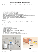
Typical Installation
Key:
A Tank Stand - A (Red)
B Tank Stand - B (Blue)
C AC Power Pack
D HFR Power Pack
E Dispense Gun
F Fluid Temperature Sensor (FTS)
G Manifold
H Main Hose Bundle
J Whip Hose Bundle
F
IG
. 1: Typical Installation
* Shown exposed for clarity.
Wrap with tape during operation.
ti19507a
F*
A
H
E
J
D
C
B
G

Component Identification
14 3A2797G
Component Identification
Key for F
IG
. 2 and F
IG
. 3.
AA Advanced Display Module (see page 20)
BA Component A (Red) Pressure Relief Outlet
BB Component B (Blue) Pressure Relief Outlet
FA Component A (Red) Fluid Manifold Inlet (on left side of
manifold block)
FB Component B (Blue) Fluid Manifold Inlet
FM HFR Fluid Manifold
FP Feed Inlet Pressure Gauge
FT Feed Inlet Temperature Gauge
GA Component A (Red) Outlet Pressure Gauge
GB Component B (Blue) Outlet Pressure Gauge
HA Component A (Red) Hose Connection (from feed to gun
or mix head)
HB Component B (Blue) Hose Connection (from feed to gun
or mix head)
HP Hydraulic Power Pack Assembly
HT Hydraulic Tank
LS Pumpline Linear Sensor
MA Motor Control Module, see page 18
MP Main Power Switch
PA Component A (Red) Pump
PB Component B (Blue) Pump
PD Power Distribution Box
PHB Primary Heater - B Side
PHA Primary Heater - A Side
PI Primary Heater Fluid Inlet
PO Primary Heater Fluid Outlet
PR Primary Heater RTD
PS Primary Heater Overtemperature Switch
SA Component A (Red) PRESSURE RELIEF/DISPENSE
Valve
SB Component B (Blue) PRESSURE RELIEF/DISPENSE
Valve
TA Component A (Red) Pressure Transducer
TB Component B (Blue) Pressure Transducer
TC High Power Temperature Control Module (not shown, see
page 24)
F
IG
. 2: Component Identification, Heated Model shown with shrouds removed
PA
PB
FP
AA
HP
FM
PD
HT
MA
FP
FT
ti19508a

Component Identification
3A2797G 15
F
IG
. 3: Component Identification, Continued
ti9880a1
GA
GB
SB
FB
BB
HB
HA
BA
FA
SA
Fluid Manifold (FM) Detail
LS
TB
TA
MP
Rear View
Primary Heater (PHA)
Detail, A (Red) side shown
ti19509a
ti19510a
PO
PR
PS
PI
Primary Heater (PHB)
Detail, B (Blue) side shown
ti19511a
PI
PO
PR
PS
(In Enclosure)

Component Identification
16 3A2797G
Main Power Switch
Located on top of the power distribution box, see
page
14
. The main power switch turns power
ON and OFF . The main power switch
does not turn pumps or heat zones on.
Circuit Breakers
Most circuit breakers are located inside the power distri-
bution box. The main block of circuit breakers in the
power distribution box is shown below, with detailed
information in the following table. For more information
about items in the power distribution box, see power dis-
tribution box manual.
Ref.
Size
Component
400V/
3 phase
230V/
3 phase
CB1 63A 30A Motor Control Module
CB2 40A 40A Primary Heater A
CB5 5A 5A Miscellaneous
CB6 5A 5A Miscellaneous
CB9 40A 40A Primary Heater B
CB11 30A 30A AC Power Pack
CB1
CB5
CB2
CB9
CB6
CB11
400V/ 3 phase
230V/ 3 phase
ti19512a
ti19513a

Component Identification
3A2797G 17
HFR Hydraulic Power Pack
Key:
DA 9 Gallon Hydraulic Oil Reservoir (see Technical Data on
page 95 for specifications)
DB Electric Motor
DD Hydraulic Housing
DE Directional Valve
DF Motor Control Module (see page 18)
DG Fan
DH Oil Filter
DJ Shroud (not shown, removed for clarity)
DK 3 Way Splitter
DL Oil Level Sensor (Optional)
F
IG
. 4: HFR Hydraulic Power Pack
ti19514a
DB
DE
DA
DG
DD
DH
DF
DK
DL

Component Identification
18 3A2797G
Motor Control Module (MCM)
For MCM location, see reference MA in F
IG
. 2 on
page 14. When installed, the end of the MCM with the
power input connection (12) faces down and the end
with the access cover (A) faces up.
The Motor Control Module uses an 8-position selector
switch to set the system maximum working pressure.
NOTICE
If the Motor Control Module is replaced, the selector
switch must be set prior to initial startup of the
Motor Control Module or damage may occur. See
HFR Repair manual for details, see Related Manu-
als on page 3.
F
IG
. 5: MCM Component Identification
A
r_257396_3b9905_01b
r_257396_3b9905_03b
C
12
B
13
1A
11
1B
5
7
6
8
9
10
2
3

Component Identification
3A2797G 19
Diagnostic Information
7
Ref Description
A Access Cover
B LEDs
C Warning Label
1A, 1B CAN Connections
2 Three-way Splitter to: Oil Low Level
Sensor, Dispense Valve Solenoid, and
Footswitch
3 Oil Temperature Sensor
5 Electric Motor Temperature Sensor
6 LVDT (Position Sensor)
7 Three-way Splitter to:
Hydraulic Directional Valve,
Oil Overtemperature Switch
8 Pressure Transducer B (Blue) side
9 Pressure Transducer A (Red) side
10 Not used
11 Motor Position Sensor
12 MCM Power Input Connection
13 Motor Power Connection
Table 1: LED (Ref B) Status Signal
Module Status LED Signal Description
Green on System is powered up.
Yellow on Internal communication in progress.
Red solid MCM hardware failure. Replace MCM.
Red flashing fast Uploading software.
Red flashing slow Token error. Remove token and upload
software token again.

Component Identification
20 3A2797G
Advanced Display Module (ADM)
User Interface
Buttons
System Status Indicator (CB) Conditions
Green Solid - Run Mode, System On
Green Flashing - Setup Mode, System On
Yellow Solid - Run Mode, System Off
F
IG
. 6: ADM Component Identification - Front
TI12362a1
CA
CB
CC
CE
CH
CG
CF
CD
CF
Ref. Button Function
CA System
enable/
disable
Enables/disables system. When sys-
tem is disabled, temperature control
and dispense operation are disabled.
CB System
Status
Indicator
Light
Displays system status. See System
Status Indicator (CB) Conditions on
page 20 for details.
CC Stop Stop all system processes.
CD Soft Keys Defined by application using ADM.
CE Cancel Cancel a selection or number entry
while in the process of entering a
number or making a selection.
CF Enter Acknowledge changing a value or
making a selection.
CG Setup Toggle between run and setup
screens or password screen if setup
screens are password protected.
CH Naviga-
tion
Navigate within a screen or to a new
screen.
/