Page is loading ...

Instructions - Parts
Stainless Steel
Tank Stands
For supplying material to HFR
™
plural-component proportioners. For professional use
only.
Not approved for use in European explosive atmosphere locations.
100 psi (0.7 MPa, 7.0 bar) Maximum Working Pressure
100 psi (0.7 MPa, 7.0 bar) Maximum Air Pressure
See page 3 for model information.
Important Safety Instructions
Read all warnings and instructions in this
manual. Save these instructions.
r_24C317_3A0395a_1c
3A0395R
EN

2 3A0395R
Contents
Models . . . . . . . . . . . . . . . . . . . . . . . . . . . . . . . . . . . 3
Related Manuals . . . . . . . . . . . . . . . . . . . . . . . . . . . 3
Warnings . . . . . . . . . . . . . . . . . . . . . . . . . . . . . . . . . 4
Important Two-Component Material Information . 6
Isocyanate Conditions . . . . . . . . . . . . . . . . . . . . . 6
Material Self-ignition . . . . . . . . . . . . . . . . . . . . . . 6
Keep Components A and B Separate . . . . . . . . . 6
Moisture Sensitivity of Isocyanates . . . . . . . . . . . 6
Foam Resins with 245 fa Blowing Agents . . . . . . 6
Changing Materials . . . . . . . . . . . . . . . . . . . . . . . 7
Component Identification . . . . . . . . . . . . . . . . . . . . 8
Tank Feed System . . . . . . . . . . . . . . . . . . . . . . . 8
Electrical Panel Components . . . . . . . . . . . . . . . 9
Installation . . . . . . . . . . . . . . . . . . . . . . . . . . . . . . . 12
Grounding . . . . . . . . . . . . . . . . . . . . . . . . . . . . . 12
Install Tank Stand . . . . . . . . . . . . . . . . . . . . . . . 12
Install Barrel Style Level Sensors . . . . . . . . . . . 12
Install Ultrasonic Level Sensor . . . . . . . . . . . . . 14
Install Chiller (customer supplied) . . . . . . . . . . . 14
Auto-Refill Installation: customer supplied feed
system . . . . . . . . . . . . . . . . . . . . . . . . . . . . 15
Auto-Refill Installation: Graco supplied feed system
15
Setup . . . . . . . . . . . . . . . . . . . . . . . . . . . . . . . . . . . . 16
Calibrate Barrel Style Level Sensors . . . . . . . . . 16
Vacuum De-gas . . . . . . . . . . . . . . . . . . . . . . . . . 16
Operation . . . . . . . . . . . . . . . . . . . . . . . . . . . . . . . . 17
Startup . . . . . . . . . . . . . . . . . . . . . . . . . . . . . . . 17
Pressure Relief Procedure . . . . . . . . . . . . . . . . 17
Maintenance . . . . . . . . . . . . . . . . . . . . . . . . . . . . . . 18
Daily Maintenance . . . . . . . . . . . . . . . . . . . . . . 18
Weekly Maintenance . . . . . . . . . . . . . . . . . . . . . 18
Install Upgrade Tokens . . . . . . . . . . . . . . . . . . . 18
Troubleshooting . . . . . . . . . . . . . . . . . . . . . . . . . . . 19
Repair . . . . . . . . . . . . . . . . . . . . . . . . . . . . . . . . . . . 27
Replace Agitator Fuse . . . . . . . . . . . . . . . . . . . 27
Tank Lid Gasket . . . . . . . . . . . . . . . . . . . . . . . . 27
Level Sensor and Well . . . . . . . . . . . . . . . . . . . 29
Electrical Schematics . . . . . . . . . . . . . . . . . . . . . . 30
Electrical Panel, Tank Stand with Agitator,
Heater/Chiller . . . . . . . . . . . . . . . . . . . . . . . 30
Electrical Panel, Tank Stand with Agitator . . . . . 34
Parts . . . . . . . . . . . . . . . . . . . . . . . . . . . . . . . . . . . . 37
38L and 75L Tank Modules . . . . . . . . . . . . . . . . 37
2 Gallon Tank Module - 24J243 . . . . . . . . . . . . . 43
Heated Tank Assemblies . . . . . . . . . . . . . . . . . . 46
Tank Lid Assemblies . . . . . . . . . . . . . . . . . . . . . 47
Electrical Panel, 230V for Heat . . . . . . . . . . . . . 50
Electrical Panel, 230V for No Heat . . . . . . . . . . 51
Electrical Panel, 230V for 2 Gallon Tanks Only . 54
Heat Exchanger Assembly . . . . . . . . . . . . . . . . 56
Air Dryer Filter . . . . . . . . . . . . . . . . . . . . . . . . . . 57
Ball Valve Assemblies . . . . . . . . . . . . . . . . . . . . 58
Recirculation Probe Assembly . . . . . . . . . . . . . . 59
Transfer Pump Valve, 24C157 . . . . . . . . . . . . . . 60
Accessories and Kits . . . . . . . . . . . . . . . . . . . . . . . 61
Dimensions . . . . . . . . . . . . . . . . . . . . . . . . . . . . . . . 66
Technical Data . . . . . . . . . . . . . . . . . . . . . . . . . . . . 67
Graco Standard Warranty . . . . . . . . . . . . . . . . . . . 68

Models
3A0395R 3
Models
The following table lists the tank stand module part numbers and the components included with each.
Related Manuals
Component manuals listed below are in English. Manu-
als are available at www.graco.com.
Part
Includes:
Agitator
Slinger
Plate Heat Insulation Chiller
Desiccant
Dryer
Level
Sensors
46 Liter Tanks
24D562
✔✔ ✔
24D564
✔✔✔✔
24D568
24D569
✔
24D570
✔✔
24D571
✔✔ ✔
24D572
✔✔✔ ✔ ✔
24D573
✔✔✔ ✔
75 Liter Tanks
24D565
✔✔ ✔
24C317
✔✔✔✔
24D574
24D575
✔
24D576
✔✔
24D577
✔✔ ✔
24D578
✔✔✔ ✔ ✔
24D579
✔✔✔ ✔
24P091
✔✔✔✔✔
7.5 Liter Tanks
24J243
✔
Manual No.
Description
3A1936 Pneumatic and Electric Agitator Kits
3A1962 Pneumatic and Electric Agitators with
Heat Blanket Kits

Warnings
4 3A0395R
Warnings
The following warnings are for the setup, use, grounding, maintenance, and repair of this equipment. The exclama-
tion point symbol alerts you to a general warning and the hazard symbols refer to procedure-specific risks. When
these symbols appear in the body of this manual, refer back to these Warnings. Product-specific hazard symbols and
warnings not covered in this section may appear throughout the body of this manual where applicable.
WARNINGWARNINGWARNING
WARNING
ELECTRIC SHOCK HAZARD
This equipment must be grounded. Improper grounding, setup, or usage of the system can cause electric
shock.
• Turn off and disconnect power at main switch before disconnecting any cables and before servicing
equipment.
• Connect only to grounded power source.
• All electrical wiring must be done by a qualified electrician and comply with all local codes and regula-
tions.
PRESSURIZED EQUIPMENT HAZARD
Fluid from the gun/dispense valve, leaks, or ruptured components can splash in the eyes or on skin and
cause serious injury.
•Follow the Pressure Relief Procedure when you stop spraying and before cleaning, checking, or ser-
vicing equipment.
• Tighten all fluid connections before operating the equipment.
• Check hoses, tubes, and couplings daily. Replace worn or damaged parts immediately.
TOXIC FLUID OR FUMES HAZARD
Toxic fluids or fumes can cause serious injury or death if splashed in the eyes or on skin, inhaled, or swal-
lowed.
• Read MSDSs to know the specific hazards of the fluids you are using.
• Store hazardous fluid in approved containers, and dispose of it according to applicable guidelines.
• Always wear chemically impermeable gloves when spraying, dispensing, or cleaning equipment.
PERSONAL PROTECTIVE EQUIPMENT
You must wear appropriate protective equipment when operating, servicing, or when in the operating area
of the equipment to help protect you from serious injury, including eye injury, hearing loss, inhalation of
toxic fumes, and burns. This equipment includes but is not limited to:
• Protective eyewear, and hearing protection.
• Respirators, protective clothing, and gloves as recommended by the fluid and solvent manufacturer

Warnings
3A0395R 5
FIRE AND EXPLOSION HAZARD
Flammable fumes, such as solvent and paint fumes, in work area can ignite or explode. To help prevent
fire and explosion:
• Use equipment only in well ventilated area.
• Eliminate all ignition sources; such as pilot lights, cigarettes, portable electric lamps, and plastic drop
cloths (potential static arc).
• Keep work area free of debris, including solvent, rags and gasoline.
• Do not plug or unplug power cords, or turn power or light switches on or off when flammable fumes
are present.
• Ground all equipment in the work area. See Grounding instructions.
• Use only grounded hoses.
• Hold gun firmly to side of grounded pail when triggering into pail.
• If there is static sparking or you feel a shock, stop operation immediately. Do not use equipment
until you identify and correct the problem.
• Keep a working fire extinguisher in the work area.
EQUIPMENT MISUSE HAZARD
Misuse can cause death or serious injury.
• Do not operate the unit when fatigued or under the influence of drugs or alcohol.
• Do not exceed the maximum working pressure or temperature rating of the lowest rated system com-
ponent. See Technical Data in all equipment manuals.
• Use fluids and solvents that are compatible with equipment wetted parts. See Technical Data in all
equipment manuals. Read fluid and solvent manufacturer’s warnings. For complete information about
your material, request MSDS from distributor or retailer.
• Do not leave the work area while equipment is energized or under pressure. Turn off all equipment
and follow the Pressure Relief Procedure when equipment is not in use.
• Check equipment daily. Repair or replace worn or damaged parts immediately with genuine manufac-
turer’s replacement parts only.
• Do not alter or modify equipment.
• Use equipment only for its intended purpose. Call your distributor for information.
• Route hoses and cables away from traffic areas, sharp edges, moving parts, and hot surfaces.
• Do not kink or over bend hoses or use hoses to pull equipment.
• Keep children and animals away from work area.
• Comply with all applicable safety regulations.
BURN HAZARD
Equipment surfaces and fluid that’s heated can become very hot during operation. To avoid severe burns:
• Do not touch hot fluid or equipment.
WARNINGWARNINGWARNING
WARNING

Important Two-Component Material Information
6 3A0395R
Important Two-Component Material Information
Isocyanate Conditions
Material Self-ignition
Keep Components A and B
Separate
Moisture Sensitivity of
Isocyanates
Isocyanates (ISO) are catalysts used in two component
foam and polyurea coatings. ISO will react with moisture
(such as humidity) to form small, hard, abrasive crystals,
which become suspended in the fluid. Eventually a film
will form on the surface and the ISO will begin to gel,
increasing in viscosity. If used, this partially cured ISO
will reduce performance and the life of all wetted parts.
NOTE: The amount of film formation and rate of crystal-
lization varies depending on the blend of ISO, the
humidity, and the temperature.
To prevent exposing ISO to moisture:
• Always use a sealed container with a desiccant
dryer in the vent, or a nitrogen atmosphere. Never
store ISO in an open container.
• Keep the ISO lube pump reservoir (if installed) filled
with Graco Throat Seal Liquid
™
(TSL
™
), Part
206995. The lubricant creates a barrier between the
ISO and the atmosphere.
• Use moisture-proof hoses specifically designed for
ISO, such as those supplied with your system.
• Never use reclaimed solvents, which may contain
moisture. Always keep solvent containers closed
when not in use.
• Never use solvent on one side if it has been contam-
inated from the other side.
• Always lubricate threaded parts with ISO pump oil
or grease when reassembling.
Foam Resins with 245 fa
Blowing Agents
Some foam blowing agents will froth at temperatures
above 90°F (33°C) when not under pressure, especially
if agitated. To reduce frothing, minimize preheating in a
circulation system.
Spraying or dispensing materials containing isocya-
nates creates potentially harmful mists, vapors, and
atomized particulates.
Read material manufacturer’s warnings and material
MSDS to know specific hazards and precautions
related to isocyanates.
Prevent inhalation of isocyanate mists, vapors, and
atomized particulates by providing sufficient ventila-
tion in the work area. If sufficient ventilation is not
available, a supplied-air respirator is required for
everyone in the work area.
To prevent contact with isocyanates, appropriate per-
sonal protective equipment, including chemically
impermeable gloves, boots, aprons, and goggles, is
also required for everyone in the work area.
Some materials may become self-igniting if applied
too thickly. Read material manufacturer’s warnings
and material MSDS.
Cross-contamination can result in cured material in
fluid lines which could cause serious injury or dam-
age equipment. To prevent cross-contamination of
the equipment’s wetted parts, never interchange
component A (isocyanate) and component B (resin)
parts.

Important Two-Component Material Information
3A0395R 7
Changing Materials
• When changing materials, flush the equipment mul-
tiple times to ensure it is thoroughly clean.
• Always clean the fluid inlet strainers after flushing.
• Check with your material manufacturer for chemical
compatibility.
• Most materials use ISO on the A side, but some use
ISO on the B side.
• Epoxies often have amines on the B (hardener)
side. Polyureas often have amines on the B (resin)
side.

Component Identification
8 3A0395R
Component Identification
Tank Feed System
Key:
A Air Pressure Gauge and Valve
B Lid or Lid with Agitator
CTank
D Material Valve
E Recirculation Probe Assembly
F Ball Valve Assembly
G Heat Exchanger Assembly
HEnclosure
J Level Sensors (not shown)
FIG. 1: Component Identification - Tank Feed System
r_24C317_3A0395a_1c
A
B
C
D
E
F
G
H

Component Identification
3A0395R 9
Electrical Panel Components
The electrical panel is located on the inside of the tank
stand enclosure, and includes the circuit breakers, a
fluid control module, and a low power temperature con-
trol module.
Circuit Breakers
FIG. 2: Component Identification - Circuit Breakers
CB130
CB115
Ref. Size Component
CB115 5A Agitator
CB130 10A Low power temperature control
module / heat blanket / chiller

Component Identification
10 3A0395R
Fluid Control Module (FCM)
Key:
AA Fluid Control Module (FCM)
AB Base
AC Module Connection Screws
AD Access Cover
AE Module Status LEDs
AF CAN Connectors
AG Level Sensor Input
AH Fill Solenoid Signal
Low Power Temperature Control Module
Key:
BA Low Power Module
BB RTD Temperature Sensor Connection (for chiller or for
RTD in bottom of tank when using a heated blanket)
BC Output Power Connection
BD Input Power Connection
BE CAN Connectors
BF Base
BG RTD Temperature Sensor Connection (for RTD under
heated blanket)
FIG. 3: Component Identification - FCM
ti12336a
AA
AB
AC
AD
ti12337a
AG
AE
AH
AF
FIG. 4: Component Identification - Low Power Module
BB
BF
BC
BE
BD
ti12356a
ti12357a
BA
BG

Component Identification
3A0395R 11
Heat Zone and Fluid Control Selection
The tank feed system supports independent tempera-
ture control by utilizing a low power temperature control
module. The system also supports fluid control by utiliz-
ing an FCM. Both the low power temperature control
module and the FCM are located on the electrical panel
within the enclosure.
NOTE: Tank stands are configured for the A (Red)
side. Adjust rotary switch setting if tank is being
used on B (Blue) side.
Adjust Rotary Switch
The rotary switch setting indicates which zone the tem-
perature control module will control in the system. The
low power module and FCM use a 16-position rotary
switch to make selections.
Set the rotary switch to the specific selection according
to the settings listed in the following tables.
Low Power Temperature Control Module Rotary Switch
Settings
FCM Rotary Switch Settings
FIG. 5: Electrical Panel
FIG. 6: Adjust Rotary Switch
FCM
Low
Power
Temp
Control
r_24C169_3A0395_1a
Rotary Switch
ti12361a
Setting Zone
0-4 Not Used
5 B (Blue) Tank Heater
6 A (Red) Tank Heater
7 B (Blue) Chiller
8 A (Red) Chiller
9-F Not Used
Setting Zone
0-2 Not Used
3 B (Blue) Tank Refill
4 A (Red) Tank Refill
5-F Not Used

Installation
12 3A0395R
Installation
Grounding
Products that include heated tanks must be grounded.
Grounding reduces the risk of static and electric shock
by providing an escape wire for the electrical current
due to static build up or in the event of a short circuit.
Improper installation of the grounding plug increases the
risk of electric shock. Do not modify the plug provided; if
it does not fit the outlet, have the proper outlet installed
by a qualified electrician. Only connect the product to an
outlet having the same configuration as the plug. Do not
use an adapter with this product.
Install Tank Stand
1. Install the tank stand no more than 6 ft. (1.8 m) from
the rear of the material pumps on the HFR system.
2. Anchor the tank stand to the floor. (Suggested
anchors: McMaster-Carr anchor, 92403A400.) See
Dimensions, page 66.
3. Plug the tank stand power cable into the bottom of
the HFR power distribution box.
4. Plug the tank stand CAN cable into the CAN splitter
inside the distribution box.
NOTE: Tank stands are configured for the A (Red)
side. Adjust rotary switch setting if tank is being
used on B (Blue) side.
Install Barrel Style Level
Sensors
1. Turn main power off.
2. Relieve tank air pressure. See Pressure Relief Pro-
cedure, page 17.
3. Drain tanks below the lowest level sensor well.
If installing high temperature level sensors:
4. Apply PTFE paste and PTFE tape to the male
threads of the level sensor.
5. Being careful to not cross-threads, thread the level
sensor (CB) into the corresponding tank port.
6. Plug the sensor cable adapter into the level sensor.
7. Plug the sensor connector (CD) into the level sensor
adapter.
8. Plug the sensor connector into the connector on the
FCM.
If installing low temperature level sensors:
NOTE: For proper level sensor function, the tip of
the level sensor well must protrude at least 1/8 in.
into the tank (C).
NOTICE
To avoid improper operation, ensure the mark (dot
or arrow) found on the hex of the level sensor is
pointing towards the top or bottom of the machine
after tightening.

Installation
3A0395R 13
9. Route each level sensor (H) wire (J1, J2, J3)
through the corresponding well nut (CC). See F
IG. 8
for wire location on tank.
10. Measure the length of the level sensor well housing,
and then measure the depth of the hole in the tank
where the well is inserted. Note these measure-
ments as they will be need later.
11. Being careful to not cross-threads, thread assem-
bled level sensor (CB) into well housing until it bot-
toms out against the bottom of the well. The bottom
of the level sensor will be slightly visible through the
bottom of the well.
NOTE: In the following step, do not allow PTFE
paste or tape to cover the tip of the level sensor
well. If paste comes in contact with the tip of the
level sensor well, thoroughly wipe it clean.
12. Apply PTFE paste and PTFE tape to the male
threads of the level sensor well housing.
13. Being careful to not cross-threads, thread the level
sensor well (CA) into the corresponding tank port
and lightly tighten with a crescent wrench.
14. Measure the amount of the level sensor well hous-
ing that is visible beyond the day tank hole, then
perform the following equation:
15. The protrusion length must be at least 1/8 in.
(3.2 mm). If not, remove the level sensor well and
restart at step 10.
16. Rotate level sensor to optimal position for wire rout-
ing.
17. Plug the sensor connector (CD) into the level sen-
sors.
18. Plug the sensor connector into the connector on the
FCM.
19. Calibrate the sensor. See Calibrate Barrel Style
Level Sensors, page 16.
FIG. 7: Level Sensor Assembly
r_24b969_3A0395a_7a
CA
CB
CC
CD
Wires
FIG. 8: Tank Ports
Ensure the level sensors are installed in the sensor
well housings before pressurizing the tank. Failing to
do so could cause the well housings to rupture, which
may result in serious injury and material leakage.
J3
J2
J1
P = L1 - (L2 + L3)
P = Protrusion length (inside of day tank)
L1 = Length of level sensor well
L2 = Visible length of level sensor well
L3 = Length of well threads in day tank

Installation
14 3A0395R
Install Ultrasonic Level Sensor
NOTE: The ultrasonic level sensor is only used on two
gallon tanks.
1. Turn main power off.
2. Relieve tank air pressure. See Pressure Relief Pro-
cedure, page 17.
3. Drain tank.
4. Remove the tank lid (DA).
5. Insert the o-ring (DB) and sensor well housing (DC)
into the tank port.
6. Tighten the jam nut (DD) to ensure there will not be
any air leakage.
7. Hand tighten the level sensor (DE).
8. Plug the sensor connector into the connector on the
FCM.
Install Chiller (customer
supplied)
The following instructions apply to tank modules
(24C317, 24D562, 24D564, 24D565) that include the
heat exchanger assembly (G).
NOTE: Graco does not supply the chiller assembly.
1. Connect incoming water to inlet heat exchanger
port.
2. Connect outgoing water to outlet heat exchanger
port.
3. Configure the advanced display module (ADM) for
the chiller option. See the HFR Setup-Operation
manual for instructions.
FIG. 9: Ultrasonic Level Sensor
ti17772a
DA
DD
DB
DC
DE
FIG. 10: Level Sensor Assembly
r_24C317_3A0395a_1c
Water Inlet
Water Outlet

Installation
3A0395R 15
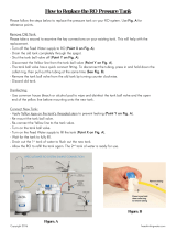
Auto-Refill Installation:
customer supplied feed system
NOTE: The auto-refill assembly is not assembled
when shipped.
1. Empty tank (C).
2. Remove plug from lower, rear of tank.
3. Install auto-refill assembly in 3/4 npt port.
4. Connect hose (not supplied) to 1/2 npt port on
material valve.
5. Connect air lines from air valve (A) to material valve
(D).
6. Connect main air line to air valve.
Auto-Refill Installation: Graco
supplied feed system
NOTE: The auto-refill assembly is not assembled
when shipped.
1. Empty tank (C).
2. Remove plug from lower, rear of tank.
3. Connect feed pump outlet hose to tank.
4. Connect air lines from air valve to feed pump.
5. Connect main air line to air valve.
FIG. 11: Tank Assembly
Material
Air Solenoid
Valve
Valve
Air Line
Air Valve
r_24C317_3A0395a_10b

Setup
16 3A0395R
Setup
Calibrate Barrel Style Level
Sensors
NOTE: Calibration is not required for ultrasonic
style level sensors or high temperature level sen-
sors.
1. Locate the calibration button on the sensor (11)
closest to the electrical connector through one of
the four holes of the sensor well housing (CA).
2. If the calibration button cannot be seen through one
of the four holes in the sensor well, rotate the sen-
sor.
a. Loosen the sensor well nut (CC).
b. Rotate sensor until the calibration button can be
seen through one of the four holes in the sensor
well housing.
c. Tighten sensor well nut.
d. Press and hold the button down with the ball
end of an allen wrench for two seconds. The
light will flash slowly and then go out.
3. Test for proper sensor function.
a. Loosen the sensor well nut.
b. Back the sensor out of the well. The sensor
should sense the tank wall.
Vacuum De-gas
NOTE: Only perform the following procedures for
tank volumes other than two gallons.
1. Shut down the HFR system. Refer to the HFR
Setup-Operation manual for instructions.
2. Close the shut-off ball valves at the base of the
tanks.
3. If the tank lid has a fill port, turn off any systems that
might refill the tank during the vacuum de-gas pro-
cedure.
4. Close the fill port ball valve.
5. If the tank lid requires a desiccant dryer, install it into
the top ball valve of the vacuum tree manifold.
6. Close the top ball valve of the vacuum tree manifold.
7. Attach vacuum pump to the bottom ball valve of the
vacuum tree manifold. Open the ball valve.
8. Turn on the vacuum pump.
9. Continue to de-gas the material.
10. Close bottom ball valve of the vacuum tree manifold.
11. Turn off the vacuum pump.
12. Open the top ball valve of the vacuum tree manifold.
13. Open the shutoff valves at the base of the tanks.
NOTICE
Operating the tank after the vacuum de-gas proce-
dure without the top ball valve open will result in
pump cavitation, off-ratio conditions, and possible
collapse of the tank.

Operation
3A0395R 17
Operation
See HFR Setup-Operation manual for system operation
instructions.
Startup
Start System
See HFR Setup-Operation manual for system startup
instructions.
Start Agitation
Press agitator manual switch on and off to start agita-
tion.
Pressure Relief Procedure
NOTE: Relieving air pressure in the machine means
that the supplied dry air will be replaced by moist
air. Do not leave the machine exposed to moist air
for more than 30 minutes. If the machine must be
left without air pressure for more than 30 minutes,
the day tanks must first be emptied and thoroughly
flushed.
1. Turn off main power.
2. Close day tank incoming air supply valve.
3. Disconnect pressurized air supply hose from water
separator.
4. Open the pressure relief valve on top of each day
tank to bleed air pressure from system.
5. Ensure there is no air pressure in the tanks; look at
the pressure gauges.
FIG. 12: Agitator Switch
Switch
ti17620a
FIG. 13: Tank Pressure Relief
Pressure
Gauge
Pressure
Relief
Valve

Maintenance
18 3A0395R
Maintenance
Daily Maintenance
Desiccant Dryer
Replace silica gel units when the desiccant color or
moisture indicator has changed color from Blue (mean-
ing dry) to Pink (meaning wet).
1. Turn off and depressurize the line containing the
dryer unit.
2. Loosen the camp ring and remove the bowl from the
top housing.
3. Pour out used desiccant.
4. Open new container and refill bowl
5. Shake or tap bowl to settle desiccant. Add or
remove desiccant until it is 1/8 in. below the inner
step of the bowl.
Air Filter (123377)
1. Drain water separator if necessary.
2. Pressurize the air system.
3. If desired, place a container underneath water sepa-
rator to catch water.
4. Push purge valve.
5. Release valve when filter is empty.
Weekly Maintenance
Material Filter (213062)
The red alert filter indicator provides gradual warning of
a dirty element. When the indicator displays as 3/4 red,
clean the element. If the element is not cleaned
promptly, the filter bypass valve opens and fluid will not
be filtered.
To clean the element:
1. Clean the filter element with a small paint brush.
2. Use air to blow out lodged particles.
3. Inspect for damage.
4. Replace if ruptured. See manual 307283.
Replacement Filters
• 108111 – 30 stainless steel mesh
• 108112 – 60 stainless steel mesh
• 108113 – 100 stainless steel mesh
• 108114 – 200 stainless steel mesh
• 108115 – 150 stainless steel mesh
Install Upgrade Tokens
NOTE: The Fluid Control Module and Temperature Con-
trol Module connection to the system is temporarily dis-
abled during the installation of upgrade tokens.
To install software upgrades:
1. Use correct software token stated in the table. See
Graco Control Architecture
™
Module Programming
manual for instructions.
NOTE: Upgrade all modules in the system to the
software version on the token, even if you are
replacing only one or two modules. Different soft-
ware versions may not be compatible.
All data in the module (System Settings, USB Logs,
Recipes, Maintenance Counters) may be reset to
factory default settings. Download all settings and
user preferences to a USB before the upgrade, for
ease of restoring them following the upgrade.
See manuals for locations of specific GCA compo-
nents.
The software version history for each system can be
viewed in the technical support section at
www.graco.com.
Token Application
16G584 Tank Stand:
- Fluid Control Module
- Low Power Temperature Control Module
F
IG. 14: Remove Access Cover
ti12334a1
ti12358a1

Troubleshooting
3A0395R 19
Troubleshooting
Problem Cause Solution
No agitation. Agitator motor is not turning.
Intermittent electrical connections.
Ensure the system main power is
ON.
Ensure all electrical connections to
the motor are secure. See electrical
schematic in either the HFR
Repair-Parts manual.
Check fuse at agitator switch.
Check if motor circuit breaker in
base cube has tripped. See electri-
cal schematic in either the HFR
Repair-Parts manual.
Check if tank stand circuit breaker in
power distribution module has
tripped. See electrical schematic in
either the HFR Repair-Parts man-
ual.
Replace motor.
No vacuum suction in tank. Vacuum pump is not functioning.
Vacuum lines damaged or leaking.
Check power cord from wall.
Ensure vacuum pump power is ON.
Ensure connections from vacuum
line to tank lid are secure.
Ensure there are no kinks or links in
vacuum line to tank lid.
Replace vacuum pump.

Troubleshooting
20 3A0395R
Material is not heating. Blanket heater not working.
Intermittent electrical connections.
Material temperature variations.
FCM errors.
Ensure the system main power is
ON.
Ensure all electrical connections to
the blanket heater are secure. See
electrical schematic in either the
HFR Repair-Parts manual.
Ensure the tank RTD connections
are secure. See electrical sche-
matic in either the HFR
Repair-Parts manual.
Check if FCM circuit breaker has
tripped. See electrical schematic in
either the HFR Repair-Parts man-
ual.
Check if tank stand circuit breaker in
GMS
™
power distribution box has
tripped. See electrical schematic in
either the HFR Repair-Parts man-
ual.
Check FCM. A red LED indicates a
problem with the module. See elec-
trical schematic in either the HFR
Repair-Parts manual.
Replace tank RTD.
Replace blanket heater RTD.
Replace blanket heater.
Replace FCM
Problem Cause Solution
/