Page is loading ...

This Installation Guide uses the following symbols to indicate important information.
Always observe the instructions indicated by these symbols.
VIGO INDUSTRIES INSTALLATION GUIDE FOR
SHOWER ENCLOSURE (MODEL VG06043)
Instructions that, if ignored, could result in death or serious personal injury caused by
incorrect handling or installation of the product. These instructions must be observed for
safe installation.
Maintenance and other important non-personal injury and non-material damage instructions
or statements that should be observed.
It is highly advised to dry fit the unit prior to any installation.
IMPORTANT
SAFETY PRECAUTIONS!
WARNING!
1

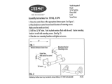
Parts List
1. Wall mount bracket (2pc)
2. Fixed panel holders (1pc)
3. Rollers (4pc)
4. Fixed panel (1pc)
5. Door (1pc)
6. Handle assembly (1pc)
7. Bottom door guide (1 pc)
8. Door threshold (1pc)
9. Vertical rail seal strip (1pc)
(pre-installed on glass)
MODEL VG06043 LUCA
NOTE: INSTALLATION MUST BE DONE BY A QUALIFIED, LICENSED PROFESSIONAL.
GLASS THICKNESS 3/8"
PLEASE READ INSTRUCTIONS BEFORE PROCEEDING
INSTALLATION INSTRUCTIONS FOR SHOWER DOOR
1
2
1
3
4
5
6
7
8
10
11
12
19
14
16
2
10.
Structural rail (1pc)
11. Door and fixed panel seal strip (2pc)
12. Door seal strip (2pc, 1 is extra)
13. Vertical rail (1pc)
14. Threshold extension clip (1 pc)
15. Plastic anchors green (6pc)
16. Plastic anchors white (2pc)
17. Phillips screw 1 1/8" (6pc)
18. Allen key pack (1 pack)
19. Hex screw 1 5/8" (2pc)
13
15
9
11
17
17

1. WALL MOUNT BRACKET
ASSEMBLY
2. FIXED PANEL HOLDER
4. FIXED PANEL WITH WALL
SIDE SEAL STRIP
6. HANDLE ASSEMBLY
8. DOOR THRESHOLD
9. VERTICAL RAIL SEAL
STRIP
11. DOOR AND FIXED
PANEL SEAL STRIP
12. DOOR SEAL STRIP
3. ROLLERS
10. STRUCTURAL RAIL
13. VERTICAL RAIL
5. DOOR
MODEL VG06043
15. PLASTIC
ANCHOR GREEN
PLASTIC ANCHOR
WHITE
16.
98087
98088
98089
97032-60x74
97033-60x74
98090
98091-60
96001
96013
95006
3
98037
PHILLIPS SCREW
1 1/8"
17.
ALLEN KEY PACK18.
98035
98038
HEX SCREW 1 5/8"
MISC
19.
7. BOTTOM DOOR GUIDE
14. THRESHOLD
EXTENSION CLIP
98092
98023
98039
96023
95005-60
PLATE

A
MODEL VG06043
C
B
4
A, B & C DIMENSIONS WERE MEASURED AFTER SHOWER ENCLOSURE WAS COMPLETELY
INSTALLED
DIMENSION "B"
(FIXED PANEL)
DIMENSION "A"
(DOOR)
HEIGHTMODEL ADJUSTABLE
DIMENSION "C"
(WIDTH)
RIGHT DOOR INSTALLATION
LEFT DOOR INSTALLATION
32 1/8" x 78 1/8"
28 1/4" x 78 3/4"
78 3/4"
VG06043XX6074
56"-60"
Product lines may change, contact your Vigo representative at 1-866-591-7792 or visit
our website at www.vigoindustries.com for the most up to date product line information.

LEFT INSTALLATIONRIGHT INSTALLATION
DOOR
DOOR
DOOR FIXED PANEL
FIG. 1A (GLASS CONFIGURATION DIAGRAM)
DOOR
FIXED PANEL
WARNING
VIGO STRONGLY RECOMMENDS THIS INSTALLATION BE COMPETED BY A LICENSED
PROFESSIONAL. INSTALLATION OF DOOR UNIT REQUIRES AT LEAST TWO PEOPLE.
REQUIRED TOOLS:
-Square and/or Phillips #1 and #2 screwdriver
-Electric drill; 1/8" drill bit for phillips screws, 3/16" drill bit for hex screws, 1/4" drill bit for green plastic
anchors or 5/16" drill bit for white plastic anchors (According to wall)
-Level
-Measuring tape
-Non permanent pencil
-Clear silicone caulking
-Utility knife; Hacksaw
If needed, remove the plastic layer of the base border. Do not remove the plastic layer off the plastic platform of
the base. Wall and base joints must be siliconed properly. To fit shower door into your opening cut structural rail
on door side only!
BEFORE INSTALLATION
See suggestion of configuration below.
PLEASE NOTE:
THE CLEAR GLASS MODEL HAS A REVERSIBLE DOOR AND CAN BE INSTALLED TO THE
RIGHT OR LEFT SIDE. (SEE CONFIGURATION DIAGRAM BELOW)
!
BEFORE STARTING
Compare items on your invoice with what you have received. Carefully review the Parts List on page 2. If any
items are missing, please call Vigo Industries at 1-866-591-7792. Please check our website at
www.vigoindustries.com for additional information or instructional videos.
IMPORTANT
Fiberglass, acrylic or sheetrock construction might not be sufficiently strong enough to support the shower
door enclosure. You should use the wood framing from behind the face edge of the stall to provide a secure
mounting to the door. Apply a bead of silicone between the walls and base of the stall.
For optimum performance, you should install the shower door perfectly level on a level surface. By not
leveling the unit during construction the unit may leak causing possible water damage.
MODEL VG06043
5
INSTALLATION OF THE SHOWER DOORS BY AN INEXPERIENCED PERSON MAY RESULT IN GLASS
BREAKAGE AND CONSEQUENTLY, CAUSE PERSONAL INJURY OR DEATH.
- Handle fragile items with care to prevent personal injury or material damage.
- The glass panels are tempered and cannot be cut. Never attempt to do so.
- Always rest glass on a level surface

IMPORTANT
Verify that the overall size of the shower door opening is appropriate for the shower enclosure.
Due to individual site variations, exact guidelines for every situation cannot be supplied. The
recommended framing and dimensional requirements are shown for a typical application and
may vary depending on the site requirements.
To prevent damage to the finish, you should protect the shower cabin bottom with a cardboard
protector before beginning the installation.
Ensure that there is sufficient structural support behind
the shower wall to hold the weight of the shower door. If
there is insufficient enough support, then reinforce the
shower walls with wooden studs prior to shower door
installation. [SEE FIG. 1]
STUDS
FIG.1
MODEL VG06043
6
INSTALLATION STEPS
A. INSTALLING THE VERTICAL RAIL / FIXED PANEL
1. Place the door panel (#5) into the shower
first making sure to rest the glass in a manner
that the glass or base/tub does not incur
damage.
A1
DOOR PANEL
(#5) INSIDE OF
THE SHOWER

7
MODEL VG06043
A2
A3
2. Position the vertical rail against the wall,
making sure the bottom rests on the floor
or base. Use a level to be sure the rail is
straight. Mark holes on the wall for the 4
mounting screws.
3. Remove the vertical rail and drill holes.
Place plastic anchors (#16) inside them.
13
16

8
MODEL VG06043
7
13
4
4
7
FRONT VIEW
FIXED
PANEL
HALF WAY
4. Replace the vertical rail and screw it into
the plastic anchors with the phillips screws
(#17). Preferred method of
installation negates anchors and has
the installation going right into the
studs. There is a 5mm adjustment on the
vertical rail (based off the depth of the
track) for any minor adjustments.
5. Place the fixed panel with the pre-installed
vertical seal strip into the vertical rail.
Lightly lift and slide the bottom door guide
(#7) half way under the fixed panel making
sure that the glass is level and plumb.
A4
A5
16
13
17
!

9
MODEL VG06043
4
OUTSIDE OF THE SHOWER
5mm
B. INSTALLING THE STRUCTURAL RAIL
1. Place the wall mount brackets (#1) on both
ends of the structural rail and lightly tighten
for dry fit purposes. Place rail into the cabin
opening. If the rail is too long, cut it with a
hacksaw to fit the opening.
Make sure to cut the rail on the door
side only.
2. Remove the fixed panel holder cover.
Place the fixed panel holder through the
hole in the fixed panel, replace the cover
and tighten. Note: There is a 5mm
horizontal adjustment in the structural
rail. If adjustments are needed, remove the
fixed panel holder cover to expose the
hollow hex screw. Using an allen key,
make your adjustments.
!
B1
B2
10
1
13
2
10
ALLEN KEY
SMALL HEX
HOLE
INSIDE OF THE SHOWER
COVER
HOLLOW HEX
ADJUSTMENT
SCREW

MODEL VG06043
10
PLATE
5mm
1
10
3. Position the fixed panel (#4) and the
structural rail assembly (#10) correctly
using a level. Mark the location of the wall
mount brackets on the wall.
4. Remove the rail from the dry fit and remove
the wall mount brackets from the structural
rail.
5. Line the outside of the wall mount brackets
with the markings on the wall. With the
plates still installed to the wall mount
brackets mark the wall at the center portion
of the plate. Note: There is a 5mm
adjustment in the wall mount bracket
plates. It is important to perform a dry
fit prior to install. Once everything is
level and plumb then you can begin
your drilling.
!
B3
B4
10
1
13
4
1
MARK THE WALL
AT THE CENTER
PORTION OF THE
PLATE WITH A
PENCIL
1
B5

MODEL VG06043
11
6. Untighten the plates from the wall mount
brackets and center the plates to the wall
markings. When installing, the center
dimension of the wall mount bracket plate
to the curb is 76 1/2" and the center
dimension of the wall mount bracket plate
to the center of the vertical rail is 7/8".
7. Install the plate by drilling holes at your
markings and place the white plastic
anchors (#16) inside them. Replace the
plates and screw them into the plastic
anchors with the hex screws (#19).
Preferred method of installation
negates anchors and has the installation
going right into the studs.
B6
B7
76 1/2"
PLATE
PLATE
This distance, 7/8", is from the center
of the vertical rail to the center of the
plate. This distance will be the same
at the fixed panel holder as it is at the
wall mount assembly. This will
ensure that the door will function
properly.
7/8"
!
PLATE
19
16
19
PLATE
16

MODEL VG06043
12
8. Slide the bracket body in position on the
structural rail. Align the plates to the rail
and slide the bracket body over the plate.
Lock the bracket body to the plate with the
supplied allen key (note the screws should
be at the top of the rail). Make sure the
structural rail is level. If the rail is not level
then loosen the bracket body, slide out of
the way and adjust the plate as needed.
There is a 5mm adjustment built in.
9. Confirm the fixed panel is installed and level
and secure the bottom door guide. Mark
the hole locations of the door bottom guide
on your curb. Carefully raise the fixed
panel and slide the bottom door guide out.
Pre-drill and sink plastic anchors (#15).
Place the bottom door guide back into
place and secure with phillips screws (#17).
Preferred method of installation
negates anchors and has the installation
going right into the studs.
B8
PLATE
HEX
SCREW
(ON TOP)
BRACKET
BODY
10
PLATE
1
10
1
B9
PLATE
5mm
VIEW FROM TOP
INSIDE OF THE SHOWER
OUTSIDE OF THE SHOWER
4
7
17
15
7
13
4
!

MODEL VG06043
13
C. INSTALLING THE DOOR
1. Remove the rollers (#3) from the box,
note that these are fully installed.
Carefully unthread the cap with a small
head allen key. You will see a big hex
screw, this is referred to as the roller
height adjustment screw.
2. Use the provided allen key to unscrew
the adjustment screw and dismantle
the roller. Place the screw through
door panel top holes and attach the
two top rollers onto the door panel
(#5).
3. Attach seal strip (#11) to both sides of
the door panel.
Start at the bottom and
work your way up, using the heel of
your hand to firmly press the seal strip
onto the glass.
ROLLER (3)
SMALL HEX
HOLE
3/8" VARIANCE
ROLLER HEIGHT
ADJUSTMENT
SCREW
ROLLER HEIGHT
ADJUSTMENT
SCREW
OUTSIDE OF
THE SHOWER
ROLLER (3)
SMALL HEX
HOLE
ROLLER HEIGHT
ADJUSTMENT
SCREW
5
5
11
C1
C2
C3

5
7
8
5
4
MODEL VG06043
14
4. Place the two top rollers and the door
panel (#5) assembly onto the
structural rail (#10).
Note that the rollers have a built-in
mechanism that will provide
adjustment for walls that are not 100%
perpendicular to the floor. If necessary,
loosen the adjustment screw and rotate the
individual roller. This will raise or lower the
height that the roller sits on the structural
rail. Please refer to pages 20-21 for
Roller Adjustments to Accommodate
Out of Square Openings. Once the rollers
are properly adjusted and the door sits
flush against the wall in the closed
position, the adjustment will be
complete. Fully tighten the adjustment
screws and re-install the roller caps.
5.
Verify that the bottom of the door rests in
the back notch of the bottom door guide
(#7).
5
10
C4
C5

MODEL VG06043
15
5
10
3
6. Screw the two bottom rollers (#3) to
the door panel as illustrated in step C2.
C6
D1
7
7
8
IMPORTANT
IN CASE THE THRESHOLD IS CUT TOO
SHORT, USE THE THRESHOLD
EXTENSION CLIP (#14) TO EXTEND
THE THRESHOLD ACCORDINGLY.
D. INSTALLING THE THRESHOLD
1. Place the threshold (#8) into the bottom
door guide (#7). Note that the end of the
threshold should go halfway inside the
bottom door guide. If the threshold is too
long, cut it with a hacksaw until it fits the
opening.

MODEL VG06043
16
2. Remove the threshold. Apply silicone to the
underside of the threshold. Place the
threshold back into its shower base location.
Align the threshold and press firmly down.
Apply silicone to the threshold around the
inside and outside of the shower base.
Remove any excess silicone from the
threshold.
8
D2
E1
E2
6
6
5
E. INSTALLING THE HANDLE
1. Unscrew the handle holders from the handle
assembly (#6).
2. Place the handle to the position on the door.
Place plastic washers (supplied) on each
side of the door.

4
4
12
This end must
look inside the
shower
MODEL VG06043
17
3. Tighten the handle nuts from inside the
shower.
E3
F1
6
5
F. INSTALLING THE WATER SEAL STRIP
1. Attach the seal strip (#12) to the fixed panel.
Start at the bottom and work your way up,
using the heel of your hand to firmly press the
seal strip onto the glass.

MODEL VG06043
18
G. APPLYING THE SILICONE
1. Apply clear silicone caulking long the wall
and floor of the shower enclosure interior.
Apply clear silicone caulking along the
fixed panel and threshold of the shower
enclosure interior.
G1
2. Trim the flange on the seal strip so that there
is enough clearance for the door to roll
without the seal strip hitting against the
rollers.
F2
5
12
Trim the flange
of the seal strip
(#12) to below
this point
12
Flange
4

MODEL VG06043
19
IMPORTANT
!
- WAIT 24 HOURS BEFORE USING SHOWER
- DO NOT ALLOW WATER TO DIRECTLY HIT DOOR SEAL STRIPS.
CLEANING INSTRUCTIONS FOR THE SHOWER CABIN AND DOOR PANEL
1. Use a mild liquid household cleaner to keep metal surfaces bright and clean. Rinse well and
dry with a soft, clean cloth.
2. Remove dust with a soft, damp cloth.
3. Use a standard household window cleaner to clean the glass panels.
4. A water beading treatment, similar to what you would use on an automobile windshield, can be
used on the inside of the glass to keep it looking brand new.
5. Use rubbing alcohol to clean and remove grease, oil, paint and ink.
6. Should you accidentally scratch or stain your shower enclosure, use a liquid automobile polish
to remove.
IMPORTANT!
1. DO NOT use abrasive cleaners, scrapers, metal brushes or any items that could scratch or dull
the surface.
2. DO NOT allow surface to come in contact with acetone (nail polish remover), dry cleaning
solution, lacquer thinner, gasoline or other similar products.
REGULAR CARE AND MAINTENANCE OF YOUR VIGO SHOWER ENCLOSURE
Your home is a moving entity, shifting and settling over time. Vigo understands this and has
designed their shower enclosures with this in mind. It is the responsibility of the homeowner or end
user to maintain the integrity of their newly installed enclosure, using the integrated adjustability
features. In order to keep your shower enclosure in optimal working condition, Vigo recommends
regularly inspecting your enclosure and tightening any hardware that may have loosened during
use. This simple step will insure optimal results from your Vigo shower enclosure for many years to
come.

IMPORTANT
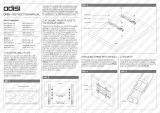
ROLLER ADJUSTMENTS TO ACCOMMODATE OUT OF SQUARE OPENINGS
1. Loosen the hex screw to allow for movement. Then place the allen key in the small hex hole as
shown and roll it to the right or left to make the adjustment. [See Fig.1]
2. Fig.1A displays the 3 different positions.
3. If your walls are plumb and level, follow the configuration in Fig. 2.
4. If your wall is off on the top, the rollers should be adjusted as shown in Fig. 3.
5. If your wall is off on the bottom, the rollers should be adjusted as shown in Fig. 4.
FIG. 1
HEX SCREW
ROLLER (3)
ROLLER (3)
SMALL HEX
HOLE
SMALL HEX
HOLE
3/8" VARIANCE
Lowest position
Normal position
Highest position
FIG. 1A
IMPORTANT
NOTE: These adjustments are approximate. You may need to adjust the direction of the small
hex hole to meet your needs.
NOTE: There is a 3mm adjustment in the roller to use in the case that your walls are not plumb
and level. Using an allen key, you will be able to adjust the roller to accommodate for the
variance.
MODEL VG06043
20
/