Toro Deluxe Seat Kit, Z Master Riding Mower Installation guide
- Type
- Installation guide
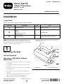
Toro Deluxe Seat Kit, Z Master Riding Mower
Toro Deluxe Seat Kit allows the adjustment of the seat position to achieve maximum comfort and control while operating the Z Master Riding Mower. With its adjustable seat suspension, you can customize the ride to suit your preference, ensuring a smooth and comfortable experience. The kit includes a seat, spacers, flange nuts, and plastic cable ties, providing everything you need for a quick and easy installation.


-
 1
1
-
 2
2
-
 3
3
-
 4
4
-
 5
5
-
 6
6
-
 7
7
-
 8
8


Toro Deluxe Seat Kit, Z Master Riding Mower Installation guide
- Type
- Installation guide
Toro Deluxe Seat Kit, Z Master Riding Mower
Toro Deluxe Seat Kit allows the adjustment of the seat position to achieve maximum comfort and control while operating the Z Master Riding Mower. With its adjustable seat suspension, you can customize the ride to suit your preference, ensuring a smooth and comfortable experience. The kit includes a seat, spacers, flange nuts, and plastic cable ties, providing everything you need for a quick and easy installation.
Ask a question and I''ll find the answer in the document
Finding information in a document is now easier with AI
Related papers
-
Toro Deluxe Seat Kit, 2000 Series Z Master Riding Mower Installation guide
-
Toro ISO Mount Seat Kit, Z Master Riding Mower Installation guide
-
Toro Z Master Commercial 2000 Series Riding Mower, User manual
-
Toro Z Master Professional 6000 Series Riding Mower, User manual
-
-
-
-
Toro Z Master Professional 5000 Series Riding Mower, User manual
-
-