
User Guide
DTP T USW 233
DTP Systems
Three Input Switcher with Integrated DTP Transmitter
68-2490-01 Rev. F
01 19

Safety Instructions
Safety Instructions • English
WARNING: This symbol, ,when used on the product, is
intended to alert the user of the presence of uninsulated dangerous
voltage within the product’s enclosure that may present a risk of electric
shock.
ATTENTION: This symbol, , when used on the product, is intended
to alert the user of important operating and maintenance (servicing)
instructions in the literature provided with the equipment.
For information on safety guidelines, regulatory compliances, EMI/EMF
compatibility, accessibility, and related topics, see the Extron Safety and
Regulatory Compliance Guide, part number 68-290-01, on the Extron
website, www.extron.com.
Sicherheitsanweisungen • Deutsch
WARNUNG: Dieses Symbol auf dem Produkt soll den Benutzer
darauf aufmerksam machen, dass im Inneren des Gehäuses dieses
Produktes gefährliche Spannungen herrschen, die nicht isoliert sind und
die einen elektrischen Schlag verursachen können.
VORSICHT: Dieses Symbol auf dem Produkt soll dem Benutzer in
der im Lieferumfang enthaltenen Dokumentation besonders wichtige
Hinweise zur Bedienung und Wartung (Instandhaltung) geben.
Weitere Informationen über die Sicherheitsrichtlinien, Produkthandhabung,
EMI/EMF-Kompatibilität, Zugänglichkeit und verwandte Themen finden Sie in
den Extron-Richtlinien für Sicherheit und Handhabung (Artikelnummer
68-290-01) auf der Extron-Website, www.extron.com.
Instrucciones de seguridad • Español
ADVERTENCIA: Este símbolo, , cuando se utiliza en el producto,
avisa al usuario de la presencia de voltaje peligroso sin aislar dentro del
producto, lo que puede representar un riesgo de descarga eléctrica.
ATENCIÓN: Este símbolo, , cuando se utiliza en el producto, avisa
al usuario de la presencia de importantes instrucciones de uso y
mantenimiento recogidas en la documentación proporcionada con el
equipo.
Para obtener información sobre directrices de seguridad, cumplimiento
de normativas, compatibilidad electromagnética, accesibilidad y temas
relacionados, consulte la Guía de cumplimiento de normativas y seguridad
de Extron, referencia 68-290-01, en el sitio Web de Extron, www.extron.com.
Instructions de sécurité • Français
AVERTISSEMENT : Ce pictogramme, , lorsqu’il est utilisé sur le
produit, signale à l’utilisateur la présence à l’intérieur du boîtier du
produit d’une tension électrique dangereuse susceptible de provoquer
un choc électrique.
ATTENTION : Ce pictogramme, , lorsqu’il est utilisé sur le produit,
signale à l’utilisateur des instructions d’utilisation ou de maintenance
importantes qui se trouvent dans la documentation fournie avec le
matériel.
Pour en savoir plus sur les règles de sécurité, la conformité à la
réglementation, la compatibilité EMI/EMF, l’accessibilité, et autres sujets
connexes, lisez les informations de sécurité et de conformité Extron, réf.
68-290-01, sur le site Extron, www.extron.com.
Istruzioni di sicurezza • Italiano
AVVERTENZA: Il simbolo, , se usato sul prodotto, serve ad
avvertire l’utente della presenza di tensione non isolata pericolosa
all’interno del contenitore del prodotto che può costituire un rischio di
scosse elettriche.
ATTENTZIONE: Il simbolo, , se usato sul prodotto, serve ad
avvertire l’utente della presenza di importanti istruzioni di funzionamento
e manutenzione nella documentazione fornita con l’apparecchio.
Per informazioni su parametri di sicurezza, conformità alle normative,
compatibilità EMI/EMF, accessibilità e argomenti simili, fare riferimento
alla Guida alla conformità normativa e di sicurezza di Extron, cod. articolo
68-290-01, sul sito web di Extron, www.extron.com.
Instrukcje bezpieczeństwa • Polska
OSTRZEŻENIE: Ten symbol, , gdy używany na produkt, ma na celu
poinformować użytkownika o obecności izolowanego i niebezpiecznego
napięcia wewnątrz obudowy produktu, który może stanowić zagrożenie
porażenia prądem elektrycznym.
UWAGI: Ten symbol, , gdy używany na produkt, jest przeznaczony do
ostrzegania użytkownika ważne operacyjne oraz instrukcje konserwacji
(obsługi) w literaturze, wyposażone w sprzęt.
Informacji na temat wytycznych w sprawie bezpieczeństwa, regulacji
wzajemnej zgodności, zgodność EMI/EMF, dostępności i Tematy pokrewne,
zobacz Extron bezpieczeństwa i regulacyjnego zgodności przewodnik, część
numer 68-290-01, na stronie internetowej Extron, www.extron.com.
Инструкция по технике безопасности • Русский
ПРЕДУПРЕЖДЕНИЕ: Данный символ, , если указан на продукте,
предупреждает пользователя о наличии неизолированного опасного напряжения
внутри корпуса продукта, которое может привести к поражению электрическим
током.
ВНИМАНИЕ: Данный символ, , если указан на продукте,
предупреждает пользователя о наличии важных инструкций
по эксплуатации и обслуживанию в руководстве,
прилагаемом к данному оборудованию.
Для получения информации о правилах техники безопасности,
соблюдении нормативных требований, электромагнитной
совместимости (ЭМП/ЭДС), возможности доступа и других
вопросах см. руководство по безопасности и соблюдению
нормативных требований Extron на сайте Extron: ,
www.extron.com, номер по каталогу - 68-290-01.
安全说明 • 简体中文
警告: 产品上的这个标志意在警告用户该产品机壳内有暴露的危险 电压,
有触电危险。
注意: 产品上的这个标志意在提示用户设备随附的用户手册中有
重要的操作和维护(维修)说明。
关于我们产品的安全指南、遵循的规范、EMI/EMF 的兼容性、无障碍
使用的特性等相关内容,敬请访问 Extron 网站 , www.extron.com,参见
Extron 安全规范指南,产品编号 68-290-01
。

안전 지침 • 한국어
경고: 이 기호 가 제품에 사용될 경우, 제품의 인클로저 내에 있는
접지되지 않은 위험한 전류로 인해 사용자가 감전될 위험이 있음을
경고합니다.
주의: 이 기호 가 제품에 사용될 경우, 장비와 함께 제공된 책자에 나와
있는 주요 운영 및 유지보수(정비) 지침을 경고합
니다.
안전 가이드라인, 규제 준수, EMI/EMF 호환성, 접근성, 그리고 관련 항목에
대한 자세한 내용은 Extron 웹 사이트(www.extron.com)의 Extron 안전 및
규제 준수 안내서, 68-290-01 조항을 참조하십시오.
Copyright
© 2013 - 2019 Extron Electronics. All rights reserved.
Trademarks
All trademarks mentioned in this guide are the properties of their respective owners.
The following registered trademarks(
®
), registered service marks(
SM
), and trademarks(
TM
) are the property of RGBSystems, Inc. or
ExtronElectronics (see the current list of trademarks on the Terms of Use page at www.extron.com):
Registered Trademarks
(
®
)
Extron, Cable Cubby, ControlScript, CrossPoint, DTP, eBUS, EDID Manager, EDID Minder, Flat Field, FlexOS, Global Configurator,
GlobalScripter, GlobalViewer, Hideaway, HyperLane, IPIntercom, IPLink, KeyMinder, LinkLicense, LockIt, MediaLink, MediaPort, NetPA,
PlenumVault, PoleVault, PowerCage, PURE3, Quantum, Show Me, SoundField, SpeedMount, SpeedSwitch, SystemINTEGRATOR,
TeamWork, TouchLink, V-Lock, VideoLounge, VN-Matrix, VoiceLift, WallVault, WindoWall, XTP, XTPSystems, and ZipClip
Registered Service Mark
(SM)
: S3 Service Support Solutions
Trademarks
(
™
)
AAP, AFL (Accu-RateFrameLock), ADSP(Advanced Digital Sync Processing), Auto-Image, CableCover, CDRS(ClassD Ripple
Suppression), Codec Connect, DDSP(Digital Display Sync Processing), DMI (DynamicMotionInterpolation), DriverConfigurator,
DSPConfigurator, DSVP(Digital Sync Validation Processing), eLink, EQIP, Everlast, FastBite, FOX, FOXBOX,
IP Intercom HelpDesk, MAAP, MicroDigital, Opti-Torque, ProDSP, QS-FPC(QuickSwitch Front Panel Controller), Room Agent,
Scope-Trigger, ShareLink, SIS, SimpleInstructionSet, Skew-Free, SpeedNav, StudioStation, Triple-Action Switching, True4K, Vector™ 4K ,
WebShare, XTRA, and ZipCaddy
安全記事 • 繁體中文
警告: 若產品上使用此符號,是為了提醒使用者,產品機殼內存在著
可能會導致觸電之風險的未絕緣危險電壓。
注意 若產品上使用此符號,是為了提醒使用者,設備隨附的用戶手冊中有
重要的操作和維護(維修)説明。
有關安全性指導方針、法規遵守、EMI/EMF 相容性、存取範圍和相關主題的詳細資
訊,請瀏覽 Extron 網站:www.extron.com,然後參閱《Extron 安全性與法規
遵守手冊》,準則編號 68-290-01。
安全上のご注意
• 日本語
警告: この記号 が製品上に表示されている場合は、筐体内に絶縁されて
いない高電圧が流れ、感電の危険があることを示しています。
注意:この記号 が製品上に表示されている場合は、本機の取扱説明書に
記載されている重要な操作と保守(整備)の指示についてユーザーの注意
を喚起するものです。
安全上のご注意、法規厳守、EMI/EMF適合性、その他の関連項目に
つ い て は 、エ ク スト ロ ン の ウ ェブ サ イト www.extron.com よ り 『 Extron Safety
and Regulatory Compliance Guide』 ( P/N 68-290-01) をご覧ください。

FCC Class A Notice
This equipment has been tested and found to comply with the limits for a Class A digital
device, pursuant to part15 of the FCC rules. The ClassA limits provide reasonable
protection against harmful interference when the equipment is operated in a commercial
environment. This equipment generates, uses, and can radiate radio frequency energy
and, if not installed and used in accordance with the instruction manual, may cause
harmful interference to radio communications. Operation of this equipment in a
residential area is likely to cause interference. This interference must be corrected at the
expense of the user.
ATTENTION: The Twisted Pair Extension technology works with shielded twisted
pair (STP) cables only. To ensure FCC Class A and CE compliance, STP cables
and STP Connectors are also required.
For more information on safety guidelines, regulatory compliances, EMI/EMF
compatibility, accessibility, and related topics, see the “Extron Safety and
Regulatory Compliance Guide” on the Extron website.
Conventions Used in this Guide
Notifications
The following notifications are used in this guide:
CAUTION: Risk of minor personal injury.
ATTENTION :
Risque de blessur
emineure.
ATTENTION:
•
Risk of pr
operty damage.
•
Risque de dommages matériels.
NOTE: A note draws attention to important information.
TIP: A tip provides a suggestion to make working with the application easier.

Software Commands
Commands are written in the fonts shown here:
^AR Merge Scene,,Op1 scene 1,1 ^B 51 ^W^C
[01]
R
0004
00300
00400
00800
00600
[02]
35
[17] [03]
E X! *X1%* X2)* X2#* X2! CE}
NOTE: For commands and examples of computer or device responses mentioned
in this guide, the character “0” is used for the number zero and “O” is the capital
letter “o.”
Computer responses and directory paths that do not have variables are written in the font
shown here:
Reply from 208.132.180.48: bytes=32 times=2ms TTL=32
C:\Program Files\Extron
Variables are written in slanted form as shown here:
ping xxx.xxx.xxx.xxx —t
SOH R Data STX Command ETB ETX
Selectable items, such as menu names, menu options, buttons, tabs, and field names are
written in the font shown here:
From the File menu, select New.
Click the OK button.
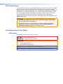
Specifications Availability
Product specifications are available on the Extron website, www.extron.com.
Extron Glossary of Terms
A glossary of terms is available at http://www.extron.com/technology/glossary.aspx.


viiDTP T USW 233 • Contents
Contents
Introduction............................................................ 1
About this Guide ................................................. 1
About the DTP T USW 233 Switcher .................. 1
STP Cable ...................................................... 2
Control Communications ................................ 2
Features ............................................................. 2
Installation and Operation .................................. 4
Mounting the Unit ............................................... 4
Connections and Reset Button ........................... 5
Rear Panel Features ....................................... 5
Connector and Cable Details .......................... 7
Front Panel Configuration Port ...................... 12
Operation ......................................................... 13
Controls and Indications ............................... 13
Front Panel Operations ................................. 14
Troubleshooting — If No Image Appears ........... 15
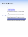
Remote Control ................................................... 16
Contact Closure Control ................................... 16
Simple Instruction Set Control .......................... 17
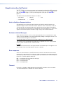
Host-to-Switcher Communications ............... 17
Switcher-Initiated Messages ......................... 17
Error responses ............................................ 17
Timeout ........................................................ 17
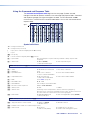
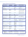
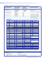
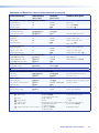
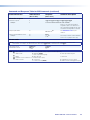
Using the Command and Response Table .... 18
Reference Information ...................................... 31
Mounting the Switcher ...................................... 31
Tabletop Use ................................................ 31
Mounting kits ................................................ 31
UL Rack-Mounting Guidelines ...................... 32
Disconnecting the Ground ................................ 32

DTP T USW 233 • Contents viii

DTP T USW 233 • Introduction 1
Introduction
• About this Guide
• About the DTP T USW 233 Switcher
• Features
About this Guide
This guide describes the Extron DTP T USW 233 switcher with an integrated DTP
transmitter. The switcher outputs a signal to a compatible DTP receiver. This guide
describes how to install, operate, and configure the switcher.
NOTE: In this guide, the DTP T USW 233 is commonly referred to as a “switcher” or a
“switching transmitter.”
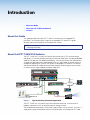
About the DTP T USW 233 Switcher
The DTP T USW 233 is a 3 input VGA and HDMI switcher with a DTP transmitter output
(see figure 1). It switches among one analog VGA and two HDMI inputs, including embedded
audio (or DVI video with the appropriate adapters). The switcher converts the selected input,
an optional analog audio input, and bidirectional RS-232 and infrared (IR) control signals to
a proprietary digital signal. It outputs the signal to a compatible DTP receiver. The switcher
and receiver extend the usable distance of video, audio, and control signals up to 230 feet
(70 meters) over a single shielded twisted pair cable (STP).
AUTO SW
CONFIG
IR OUT
HDMI IN
AUDIO IN
S
G
HDCP
1
HDMI IN
AUDIO IN
HDCP
1
2
TLP Pro 10
22T
IPCP 505
IN1608
IPCP Pro 250
Projector
100-240V ~ -- A MAX
1
2
CONFIGURABLE
HDMI
HDMI
5
6
7
8
C
RS-232 IR
RS-232IR
Tx Rx Tx RxG
Tx Rx Tx RxG
Tx Rx Tx RxG
HDMI
A
B
3
4
INPUTS
OUTPUTS
Tx Rx
RS-232
G
LAN
2x25W(8Ω)/2x50W(4Ω)
RESET
AUDIO INPUTS
OUTPUTS
REMOTE
LL1R R
L2
R
L
3
R
CLASS 2 WIRING
L4
R
L5R
+48V
+48V
12
LR
VARIABLE
IN1608 SA
2
MIC/LINE
L6
R
SIG LINK
DTP IN
SIG LINK
DTP IN
SIG LINK
DTP OUT
50/60 Hz
RS-232IR
OVER DTP
OVER DTP
OVER DTP
AMPLIFIED OUTPUT
VOLUME
SCALING PRESENTATION SWITCHER
IN1608
INPUTS
1
HDCP
SIGNAL
OUTPUTS
ENTER
MENU
Extron
2 3 4 5 6 7 8 A B C
INPUTS
1 2 3 4 5 6 7 8
CONFIG
Extron
DTP T USW 233
Transmitter
Extron
DTP T HWP 232 D Tx
Transmitter
Ethernet
Network
LR
POWER
12V
0.7A MAX
AUDIO
SIG LINK
DTP IN
OUTPUTS
XTP DTP 24 Cable
230'
230'
230'
HDMI
POWER
12V
--A MAX
G
Tx Rx RT SCTS
COM 1
G
Tx Rx
COM 2
VCG
VOL
RELAYS
1 2 C
1 2 3 4 G
DIGITAL I/O
PWR OUT = 6W
eBUS
+V+S
-S
G
LAN
IPCP PRO 250
IR/S
S G
12345678
100
LINK
ACT
COM
IR/S
TX
RX
TX
RX
RTS
CTS
R
5
1
6
2
7
3
8
4
RELAY
FLEX
I/O
5
1
6
2
3
1
4
2
eBUS
ACT LIMIT
OVER
SWITCHED
12VDC
3
1
4
OVER
2
LIMIT
IR
7
3
8
4
IPCP 505
I
N1
608
5
0
/
60 H
z
E
xtr
o
n
D
TP T U
S
W 233
T
ransmitter
XTP DTP 24
C
abl
e
2
230
'
AUTO
SWITCH
DTP T USW 233
1
2 3
CONFIG
231
STATUS
SIGNAL
HDCP
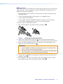
Figure 1. Typical Switching Transmitter Application
The DTP T USW 233 is housed in a half rack width metal enclosure. It can be set on a
tabletop, mounted in a rack, or mounted under or through furniture.
The included external desktop 12 VDC power supply accepts 100 to 240 VAC, 50-60 Hz. A
single power supply connected to either unit can power both units through the STP cable.

DTP T USW 233 • Introduction 2
STP Cable
Extron recommends XTP DTP 24 shielded twisted pair (STP) cable for best performance.
Extron recommends at least 24 AWG, solid conductor, STP cable with a minimum
bandwidth of 400 MHz.
ATTENTION:
•
Do
not use Extron UTP23SF-4 Enhanced Skew-Free AV UTP cable or
STP201 cable to link the switching transmitter and receiver. The DTP T USW 233
does not work properly with these cables.
•
N’utilisez pas le câble A
V Skew-FreeUTP version améliorée UTP23SF d’Extron ou
le câble STP201 pour relier les produits XTP avec les émetteurs ou les récepteurs
DTP.
Twisted pair cable is smaller, lighter, more flexible, and less expensive than coaxial
cable. The DTP 230-enabled products make cable runs simpler and less cumbersome.
Termination of the cable with RJ-45 connectors is simple, quick, and economical.
Control Communications
You can control this device through the front panel USB connector, the rear panel RS-232
connector, or through a DTP matrix. The RS-232 and IR communications are pass-through
only. The switching transmitter and receiver do not generate or respond to the RS-232 and
IR communication signals.
Features
Transmits HDMI or analog video, control, and analog audio up to 230 feet
(70 meters) over a single STP cable — The DTP T USW 233 provides high reliability and
maximum performance on an economical and easily installed cable infrastructure.
HDBaseT compatible — The DTP output can be configured to send video and embedded
audio, plus bidirectional RS-232 and IR signals to an HDBaseT-enabled display.
Inputs — Two HDMI and one RGBHV on 15-pin HD, one 3.5 mm stereo mini jack for audio.
Supports computer video to 1920x1200, including HDTV 1080p/60 Deep Color and 2K —
The DTP T USW 233 supports digital signal transmission up to 230 feet over a single
twisted pair cable and maintains superior image quality at the highest resolutions.
Analog stereo audio embedding — Analog stereo audio signals can be selectively
embedded onto the digital video output signal and transported over DTP. The HDMI inputs
can be set to pass the embedded digital audio, embed the analog audio, or to automatically
embed the analog audio when no digital audio is detected.
Accepts additional analog stereo audio signals — The DTP T USW 233 supports
a direct pass-through connection for stereo analog audio signals for simultaneous
transmission over the same single twisted pair cable. Analog audio is not embedded onto
the digital video signal. A DTP 230 receiver can output balanced and unbalanced audio,
allowing streamlined integration within an AV system.
Bidirectional RS-232 and IR insertion for AV device control — Control and IR signals
can be transmitted alongside the video signal over DTP connections, allowing the remote
device to be controlled without the need for additional cabling. Bidirectional control insertion
eliminates the need for control system wiring to remote devices.
Remote power — For simplified installation, only one power supply is necessary to power
both devices. The switcher can remotely power another connected extender or can be
powered by a connected extender or matrix switcher.

DTP T USW 233 • Introduction 3
Digital conversion of analog input signals — Analog signals are digitized, ensuring that
a reliable, high quality digital video signal is sent to the output destination.
EDID Minder — Automatically manages EDID communication between connected devices,
ensuring that all sources power up properly and reliably output content for display.
Key Minder — Authenticates and maintains continuous HDCP encryption between input
and output devices, verifying HDCP compliance for quick, reliable switching in professional
AV environments.
Compatible with all DTP 230 receivers, and DTP 230-enabled products —
Enables mixing and matching with desktop and wallplate receivers, as well as other DTP
230-enabled products to meet application requirements.

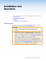
DTP T USW 233 • Installation and Operation 4
Installation and
Operation
This section describes the installation and the operation of the DTP T USW 233, including:
• Mounting the Unit
• Connections and Reset Button
• Operation
• Troubleshooting — If No Image Appears
Mounting the Unit
Mounting instructions can be found in Mounting the Switcher on page 31. Compatible
optional hardware is listed on the Extron website (www.extron.com).
ATTENTION:
•
Installation and service must be performed by authorized personnel only
.
•
L
’installation et l’entretien doivent être effectués par le personnel autorisé
uniquement.
• Avoid ground potential differences between the switching transmitter and receiver
installation sites, which can lead to equipment damage or a missing or unstable
picture. If a potential difference cannot be avoided, remove the ground connection
between the units and locally power both units (see Disconnecting the Ground
on page 32). In this configuration, the DTP T USW 233 cannot extend analog audio
and the paired receiver requires its own dedicated power supply.
•
Évitez les dif
férences de potentiel de mise à la terre entre les sites d’installation
de commutation émetteur récepteur, qui pourraient endommager l’équipement
ou rendre l’image invisible ou instable. Si une différence de potentiel ne peut être
évitée, enlevez la connexion de mise à la terre entre les unités et alimentez les deux
unités localement (voir Disconnecting the Ground à la terre page32). Dans cette
configuration, le DTPTUSW233 ne peut transmettre l’audio analogique et le
récepteur associé nécessite sa propre source d’alimentation dédiée.

DTP T USW 233 • Installation and Operation 5
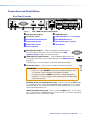
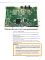
Connections and Reset Button
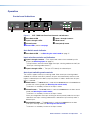
Rear Panel Features
POWER
12V
2
--A MAX
Rx GTx RxTxG
RS-232 IR
RxTx
1
RGB HDMI HDMI
HDBT
DTP
SIG LINK
DTP OUT
AUDIO
CONTACT RS-232TALLY
3
123G 123+V
RESET
INPUTS
OVER DTP REMOTE
AAKK DD CC
B
B BB FF EE GG HH JJII
.09
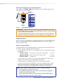
Figure 2. DTP T USW 233 Rear Panel Features
A
RGB input port (input 1)
B
HDMI input ports
C
TP function switch
D
Audio input port (see the next page)
E
Over DTP RS-232 and IR port
F
DTP Output RJ-45 port
G
Remote Contact port
H
Remote Tally port (see page 7)
I
Remote RS-232 port
J
Reset button
K
Power connector
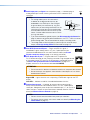
A
RGB input port (input 1) — Plug an analog (RGB) video source into
RGB
the switching transmitter via this 15-pin HD connector. See VGA
connector wiring on page 7 for connector pinout.
B
HDMI input port (inputs 2 and 3) — Plug HDMI digital video sources into
HDMI
the switching transmitter via these HDMI connectors (see HDMI connector
on page 8).
These connectors can also accept DVI video with appropriate adapters.
C
TP function switch — Set this switch as follows, based on the receiver:
ATTENTION:
•
Position this switch
BEFORE connecting the appropriate device to the
TP connector. Failure to comply can damage the endpoint.
• Positionnez le sélecteur AVANT de connecter l’appareil approprié au
connecteur TP. Ne pas respecter cette procédure pourrait endommager
le point de connexion.
Receiving device is in the Extron DTP series —Set this switch to the DTP position.
The TP output consists of HDMI with embedded audio, analog audio, RS-232 and IR,
and remote power. The switcher and receiver can be powered by one 12 VDC power
supply connected to either unit.
HDBaseT-enabled receiver type —Set this switch to HDBT position. The TP output
consists of HDMI with embedded audio plus RS-232 and IR. The switcher and receiver
each requires its own 12 VDC power supply.

DTP T USW 233 • Installation and Operation 6
D
Audio input port (see figure 2 on the previous page) — If desired, plug an
AUDIO
analog audio input into the switching transmitter via this stereo mini jack
connector.
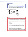
NOTES:
•
The analog audio input on this connector is
in addition to the digital audio that may be
embedded in the HDMI inputs. See the figur
e
at right to identify the connector tip, ring, and
sleeve when you are making connections for the
switching transmitter from existing audio cables.
A mono audio connector consists of the tip and
sleeve. A stereo audio connector consists of the
tip, ring, and sleeve.
Sleeve ( )
Ring (
-
)
Tip (+)
3.5 mm Stereo Plug Connector
(balanced)
• If you have removed the ground jumpers (see Disconnecting the Ground on
page 32) because of ground potential differences, the DTP T USW 233 cannot
extend analog audio. The connected receiver outputs no analog audio.
• The analog audio can be assigned to a specific input or set to be always
output (see Assign analog audio SIS commands on page 19).
E
Over DTP RS-232 and IR port — Plug a serial RS-232 signal, a
RxTx RxTxG
RS-232 IR
modulated IR signal, or both into this 3.5 mm, 5-pole captive screw
connector for bidirectional RS-232 and IR communication (see IR and
RS-232 connector wiring on page 12 to wire the connector).
F
DTP Output RJ-45 port — Plug one end of a STP cable to this
RJ-45 female connector on the switching transmitter. Plug the opposite end
of this cable into the DTP Input RJ-45 connector on a compatible receiver
(see STP cable termination and recommendations on page 9 to
properly wire the RJ-45 connector and for detailed NOTES).
ATTENTION:
• Do not connect this device to a telecommunications or computer data network.
•
Ne connectez pas ces appar
eils à des données informatiques ou à un réseau
de télécommunications.
Signal LED — Lights when the unit is outputting a TMDS clock signal on the DTP
output.
Link LED — Indicates a valid link is established between the units.
G
Remote Contact port — If desired, for contact closure control, plug a
locally-contructed contact closure device into this 3.5 mm, 4-pole captive
screw port. Momentarily short the pin for the desired input (1, 2, or 3) to G to
select that input. To force an input to be always selected, leave the short in
place (see Contact Closure Control on page 16).
NOTES:
• Contact closure control overrides front panel input selections.
• For contact closure control, auto switch mode must be off (see Selecting the
switch mode on page 15).
SIG LINK
DTP OUT
CONTACT
123G

DTP T USW 233 • Installation and Operation 7
H
Remote Tally port (see figure 2 on page 5) — If desired, to remotely identify
123
TALLY
+V
the currently selected input, plug a locally-constructed device into this 3.5
mm, 4-pole captive screw connector. Connect the power wire for the device
into the +V pin and connect the ground wire for each indicator into the
corresponding tally out pin, 1, 2, or 3.
When an input is selected, by either contact closure or front panel selection or SIS,
the corresponding tally out pin shorts to ground, closing the circuit and lighting the
connected indicator (LED).
I
Remote RS-232 port — Plug a serial RS-232 device into the switching
GRxTx
RS-232
transmitter via this 3.5 mm, 3-pole captive screw connector for remote control
of the switching transmitter (see IR and RS-232 connector wiring on
page 12 to wire the connector).
J
Reset button — The Reset button initiates two levels of reset of the switcher.
RESET
For the different reset levels, press and hold the button while the switcher is
running or while you power up the switcher (see Reset on page 15 for details).
K
Power connector — Plug the included external 12 VDC power supply into either this
2-pole connector (see Power supply wiring on page 10 to wire the connector) or
the power input connector on the receiver (see the receiver user guide on the Extron
website).
NOTES:
• The power supply included with the switching transmitter can normally power
both units.
•
If you ha
ve removed the ground jumpers (see Disconnecting the Ground on
page 32) because of ground potential differences, one unit of the pair cannot
remotely power the other unit. Each unit requires a local power supply.
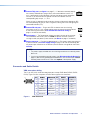
Connector and Cable Details
VGA connector wiring
The 15-pin HD (VGA) universal analog input ports accept RGB video (RGBHV, RGBS,
RGsB). Figure 3 shows the pinouts for each format type on the connector.
Pin RGBHV
1
Red
Green
Red return
Green return
Blue return
NC
Blue
RGBS/RGsB
2
Red
Green
NC
6 Red return
7 Green return
8 Blue return
3 Blue
15
11
15
4, 5
Pin RGBHV RGBS/RGsB
9
10
14
15
11
12
13
NC
Ground
V sync
NC
H sync
NC
Ground
NC
NC
NC NC
C sync
NC NC
Figure 3. VGA Connector

DTP T USW 233 • Installation and Operation 8
HDMI connector
HDMI signals run at a very high frequency and are especially prone to errors caused by bad
video connections, too many adapters, or excessive cable length. To avoid the loss of an
image or jitter, follow these guidelines:
• Do not exceed 16.4 feet (5 meters) on the input of the transmitter or the output of the
connected receiver.
• Use only the cable designed for HDMI signals that is supplied by Extron.
• Limit or avoid the use of adapters.
• Use only cables specifically intended for HDMI or DVI signals. Use of non-HDMI or
non-DVI cables or modified cables can result in a missing video output.
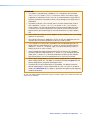
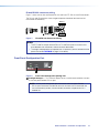
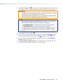
To securely fasten an HDMI cable to a device:
1. Plug the HDMI cable into the panel connection (see figure 4,
1
).
3
11
33
22
55
44
Figure 4. Installing the LockIt Lacing Bracket
2. Loosen the HDMI connection mounting screw from the panel enough to allow the
LockIt lacing bracket to be placed over it (
2
). The screw does not have to be removed.
3. Place the LockIt lacing bracket on the screw and against the HDMI connector, then
tighten the screw to secure the bracket (
3
).
ATTENTION:
• Do not overtighten the HDMI connector mounting screw. The shield to which it
fastens is very thin and can easily be stripped.
•
Ne serr
ez pas trop la vis de montage du connecteur HDMI. Le blindage auquel
elle est attachée est très fin et peut facilement être dénudé.
4.
Loosely place the included tie wrap ar
ound the HDMI connector and the LockIt lacing
bracket as shown (
4
).
5. While holding the connector securely against the lacing bracket, use pliers or similar
tools to tighten the tie wrap, then remove any excess length (
5
).

DTP T USW 233 • Installation and Operation 9
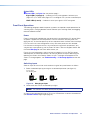
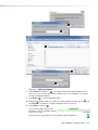
STP cable termination and recommendations
Figure 5 details the TIA/EIA T 568B wiring standard. Use this standard to terminate the
DTP cable with RJ-45 connectors.
5
Pin
1
2
3
6
7
8
4
Side
12345678
Insert
Twisted
Pair Wires
Pins:
RJ-45
Connector
Wire color
White-green
Green
White-orange
White-blue
Orange
White-brown
Brown
Blue
TIA/EIA T
568B
Figure 5. STP Cable Termination
ATTENTION: Do not use Extron UTP23SF-4 Enhanced Skew-Free AV UTP cable or
STP201 cable to link the switching transmitter and receiver. The DTP T USW 233 does
not work properly with these cables.
N’utilisez pas le câble AV Skew-FreeUTP version améliorée UTP23SF d’Extron ou le
câble STP201 pour relier les produits XTP avec les émetteurs ou les récepteurs DTP.
Supported cables
The DTP T USW 233 is compatible with shielded twisted pair (STP) and unshielded twisted
pair (U/UTP) cable. However, Extron strongly recommends that you use STP cable to
achieve best performance.
Cable recommendations
Extron recommends using the following practices to achieve full transmission distances up
to 230 feet (70 meters) and reduce transmission errors.
• Use the following Extron XTP DTP 24 STP cables and DTP 24 connectors for the best
performance:
• XTP DTP 24/1000 Non-Plenum 1000 feet (305 meters) spool 22-236-03
• XTP DTP 24P/1000 Plenum 1000 feet (305 meters) spool 22-235-03
• XTP DTP 24 Plug Package of 10 101-005-02
• If not using XTP DTP 24 cable, at a minimum, Extron recommends 24 AWG, solid
conductor, STP cable with a minimum bandwidth of 400 MHz.
• Terminate cables with shielded connectors to the TIA/EIA-T568B standard.
• Use no more than two pass-through points, which may include patch points, punch
down connectors, couplers, and power injectors. If these pass-through points are
required, use Catagory 6 or 6a shielded couplers and punch down connectors.
NOTE: When using STP cable in bundles or conduits, consider the following:
• Do not exceed 40% fill capacity in conduits.
• Do not comb the cable for the first 20 meters, where cables are straightened,
aligned, and secured in tight bundles.
• Loosely place cables and limit the use of tie wraps or hook-and-loop fasteners.
• Separate twisted pair cables from AC power cables.

DTP T USW 233 • Installation and Operation 10
Power supply wiring
NOTES:
•
The po
wer supply included with the switching transmitter can normally power both
units.
•
If you have r
emoved the ground jumpers (see Disconnecting the Ground on
page 32) because of ground potential differences, one unit of the pair cannot
remotely power the other unit. Each unit requires a local power supply.
Figure 6 shows how to wire the connector. Use the supplied tie-wrap to strap the power
cord to the extended tail of the connector.
Power Supply
Output Cord
Captive Screw
Connector
SECTION A–A
Ridges
Smooth
AA
Tie Wrap
3
5
Figure 6. Power Connector Wiring
CAUTION:
ATTENTION :
•
The wir
es must be kept separate while the power supply is plugged in. Remove
power before wiring.
•
Les deux cor
dons d’alimentation doivent être tenus à l’écart l’un de l’autre quand
l’alimentation est branchée.
•
The length of exposed wir
es is important. The ideal length is 3/16 inch (5 mm).
•
Any longer and the exposed wir
es may touch, causing a short circuit between
them.
• Any shorter and the wires can be easily pulled out even if tightly fastened by the
captive screws.
•
La longueur des câbles exposés est importante. La longueur idéale est de
5mm (3/16inches).
•
S’ils sont un peu plus longs, les câbles exposés pourraient se toucher et
pr
ovoquer un court circuit.
• S’ils sont un peu plus courts, ils pourraient sortir, même s’ils sont attachés par
les vis captives.
•
Do not tin the power supply leads befor
e installing them in the connector. Tinned
wires are not as secure in the connector and could be pulled out.
•
Ne pas étamer les conducteurs avant de les insér
er dans le connecteur. Les câbles
étamés ne sont pas aussi bien fixés dans le connecteur et pourraient être retirés.

DTP T USW 233 • Installation and Operation 11
ATTENTION:
•
This pr
oduct is intended to be supplied by a UL Listed power source marked
“Class 2” or “LPS,” rated 12 VDC, 1.0 A minimum. Always use a power supply
supplied by or specified by Extron. Use of an unauthorized power supply voids all
regulatory compliance certification and may cause damage to the supply and the
end product.
• Ce produit est destiné à une utilisation avec une source d’alimentation listéeUL
avec l’appellation «Classe2» ou «LPS» et normée 12Vcc, 1,0A minimum.
Utilisez toujours une source d’alimentation fournie ou recommandée par Extron.
L’utilisation d’une source d’alimentation non autorisée annule toute conformité
réglementaire et peut endommager la source d’alimentation ainsi que le produit
final.
• Unless otherwise stated, the AC/DC adapters are not suitable for use in air handling
spaces or in wall cavities.
•
Sauf mention contrair
e, les adaptateurs AC/DC ne sont pas appropriés pour une
utilisation dans les espaces d’aération ou dans les cavités murales.
• The installation must always be in accordance with the applicable provisions of
National Electrical Code ANSI/NFPA 70, article 725 and the Canadian Electrical
Code part 1, section 16. The power supply shall not be permanently fixed to a
building structure or similar structure.
• Cette installation doit toujours être en accord avec les mesures qui s’applique
au National Electrical Code ANSI/NFPA70, article725, et au Canadian Electrical
Code, partie1, section16. La source d’alimentation ne devra pas être fixée de
façon permanente à une structure de bâtiment ou à une structure similaire.
•
Power supply voltage polarity is critical. Incorr
ect voltage polarity can damage the
power supply and the unit. The ridges on the side of the cord (see figure 6 on the
previous page) identify the power cord negative lead.
•
La polarité de la sour
ce d’alimentation est primordiale. Une polarité incorrecte
pourrait endommager la source d’alimentation et l’unité. Les stries sur le côté du
cordon (voir l’illustration 6 sur la page 10) permettent de repérer le pôle négatif du
cordon d’alimentation.
To verify the polarity before connection, plug in the power supply with no load and check the
output with a voltmeter.

DTP T USW 233 • Installation and Operation 12
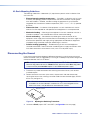
IR and RS-232 connector wiring
Figure 7 shows how to wire the Remote RS-232 and Over DTP RS-232 and IR connectors.
The RS-232 and IR connectors share the ground pole and the data from both can be
transmitted simultaneously.
TxRx
RxTx
Gnd
Gnd
IR Device
RS-232 Device
Rx
G
Tx RxTxG
RS-232 IR
RxTx
RS-232
V
OVER DTP
REMOTE
Figure 7. IR and RS-232 Connectors Wiring
NOTES:
•
The IR
Tx and Rx line pair and the RS-232 Tx and Rx line pairs must each cross
once between their connectors and the source or destination.
•
The le
ngth and preparation of exposed wires is important (see the second and third
power connector CAUTIONS on page 10 for details).
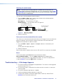
Front Panel Configuration Port
AUTO
SWITCH
CONFIG
1
MODE
AA
Figure 8. Front Panel Configuration (Config) Port
A
Configuration port — This USB mini-B port serves a similar communications function
as the rear panel Remote RS-232 port.
NOTE: A front panel configuration port connection and a rear panel Remote
RS-232 port connection can both be active at the same time. If commands are
sent simultaneously to both, the command that reaches the processor first is
handled first.
Page is loading ...
Page is loading ...
Page is loading ...
Page is loading ...
Page is loading ...
Page is loading ...
Page is loading ...
Page is loading ...
Page is loading ...
Page is loading ...
Page is loading ...
Page is loading ...
Page is loading ...
Page is loading ...
Page is loading ...
Page is loading ...
Page is loading ...
Page is loading ...
Page is loading ...
Page is loading ...
Page is loading ...
Page is loading ...
-
 1
1
-
 2
2
-
 3
3
-
 4
4
-
 5
5
-
 6
6
-
 7
7
-
 8
8
-
 9
9
-
 10
10
-
 11
11
-
 12
12
-
 13
13
-
 14
14
-
 15
15
-
 16
16
-
 17
17
-
 18
18
-
 19
19
-
 20
20
-
 21
21
-
 22
22
-
 23
23
-
 24
24
-
 25
25
-
 26
26
-
 27
27
-
 28
28
-
 29
29
-
 30
30
-
 31
31
-
 32
32
-
 33
33
-
 34
34
-
 35
35
-
 36
36
-
 37
37
-
 38
38
-
 39
39
-
 40
40
-
 41
41
-
 42
42


Ask a question and I''ll find the answer in the document
Finding information in a document is now easier with AI
in other languages
- français: Extron DTP T USW 233 Manuel utilisateur
Related papers
-
Extron DTP HDMI 4K 230 Rx User manual
-
 Extron electronics DTP T DSW 4K 333 User manual
-
Extron DTP T USW 333 User manual
-
Extron electronics DTP DVI 230 Rx User manual
-
-
Extron DTP T FB 332 User manual
-
Extron electronics XTP T VGA User manual
-
-
Extron electronics DTP HDMI 4K 330 Rx User manual
-
Extron electronics DTP2 T 202 FB User manual

Other documents
-
Extron electronic DTP T USW 233 User manual
-
SIIG CE-H25Q11-S1 Quick start guide
-
 Extron electronics XTP SR HDMI User manual
-
 Extron electronics DTP T SW4 HD 4K User manual
-
-
 Extron electronics DTP T MK 332 User manual
-
 Extron electronics USB Extender Plus R User manual
-
-
 Extron electronics DTP CrossPoint 84 IPCP User guide
-
 Extron electronics DTP HD DA8 4K 330 User manual


