Page is loading ...

cadetheat.com Tel: 855.CADET.US PO Box 1675 Vancouver, WA 98668-1675
Benets You Can Depend On
SAVE THESE INSTRUCTIONS
Com-Pak Bath Heater
Owner’s Guide
Wall Can Side
Wall Can Bottom
10”
25.4cm
11
1
/
8
”
28.3cm
3¼”
8.3cm
1¼”
3.2cm
1¾”
4.5cm
1¼”
3.2cm
3”
7.6cm
4”
10.2cm
7
7
/
8
”
20cm
½”
1.3cm
Side Grill Front
12
5
/
8
”
32.0cm
10”
25.4cm
R
E
S
E
T
R
E
S
E
T
• Best Choice for Your Bathroom
Quick heat where you need it most
Includes 60 minute timer and thermostat
Easy to install
• Our sturdiest element provides cozy warmth for
years of reliable use
• Common sense components designed with you in
mind
No sharp edges
Corrosion resistant
Easy to install wall can
• Safe for you and your family
Peace of mind with automatic high tempera-
ture shutoff feature
• Your Cadet heater has been thoroughly tested and
is guaranteed with a limited 3 year warranty
• Two models for multiple room sizes and multiple
voltage applications
(1)
Standard built-in thermostat is single pole with no heat position when turned
completely counterclockwise. Built-in 60 minute timer overrides thermostat for instant
warmth.
(2)
240 volt models can be used at 208 volts. Wattage equals 75% of 240v rated
wattage.
TOOLS REQUIRED:
• Phillips Screwdriver
• Straight Screwdriver
• Wire Strippers
• Utility Knife
• (2) 1½" Wood Screws
• (2) Insulated Wire Connectors
• (1) Strain Relief Connector
Com-Pak Bath Multi-Volt Model
Line
Voltage
Model with
Thermostat
(1)
and Timer
Watts Amps
120
CB103T
1000 8.3
240
(2)
1000 4.2
Com-Pak Bath Multi-Watt Model
Line
Voltage
Model with
Thermostat
(1)
and Timer
Watts Amps
240
(2)
CB132T
500 2.1
800 3.3
1300 5.4
Page 1
Com-Pak Bath Models
with Built-In Thermostat
and Built-In Timer
Wall Thermostat Not Required
Built-in Thermostat
Rating Label
Reset Button
Built-in Timer

SAVE THESE INSTRUCTIONS
cadetheat.com Tel: 855.CADET.US PO Box 1675 Vancouver, WA 98668-1675
IMPORTANT INSTRUCTIONS
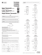
Wiring Diagrams
240/208 Volt Power Supply240 Volt Power Supply 120 Volt Power Supply
CB132T Multi-Watt
CB103T Multi-Volt
TIMER
MANUAL
RESET HIGH
TEMPERATURE
LIMIT
HEATING ELEMENT
CB
DA
MOTOR
L1 L2
36
14
THERMOSTAT
MULTI-
240V POWER SUPPLY
JUMPER WITH
INSULATED Q.D.
CONNECTOR
SPARE TERMINAL
ON ELEMENT
SHORTING BAR
TIMER
MANUAL
RESET HIGH
TEMPERATURE
LIMIT
HEATING ELEMENT
C
BA
MOTOR
240/208
VOLT
POWER
SUPPLY
L1 L2
36
14
THERMOSTAT
TIMER
MANUAL
RESET HIGH
TEMPERATURE
LIMIT
HEATING ELEMENT
CB
DA
MOTOR
L1 L2
36
14
THERMOSTAT
MULTI-
120V POWER SUPPLY
JUMPER WITH
INSULATED Q.D.
CONNECTOR
SPARE TERMINAL
ON ELEMENT
SHORTING BAR
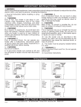
1. Read all instructions before installing or using
this heater.
2. WARNING
Risk of Fire. This heater is hot when in use.
Caution—High Temperature. Risk of Fire. Keep
electrical cords, drapery, furnishings, and other
combustibles at least 3 feet from the front of the
heater and 6 inches above and on both sides.
3. WARNING
Burn Hazard. To avoid burns, do not let bare skin
touch hot surfaces. Extreme caution is necessary
when any heater is used by or near children or
invalids and whenever the heater is left operating
and unattended.
4. WARNING
Risk of Electrical Shock. Do not operate any
heater after it malfunctions. Disconnect power
at service panel and have heater inspected by a
qualied electrician before reusing.
5. WARNING
Do not use outdoors.
6. To disconnect heater, turn controls to off, and
turn off power to heater circuit at main disconnect
panel.
7. WARNING
Risk of Electrical Shock. Do not insert or allow
foreign objects to enter any ventilation or exhaust
opening as this may cause an electric shock or
re, or damage the heater.
8. WARNING
Risk of Fire. To prevent a possible re, do not
block air intakes or exhaust in any manner.
9. WARNING
Fire or explosion may occur. A heater has hot and
arcing or sparking parts inside. Do not use it in
areas where gasoline, paint, or ammable vapors
or liquids are used or stored.
10. Use this heater only as described in this
manual. Any other use not recommended by the
manufacturer may cause re, electrical shock, or
injury to persons.
11. The heater must be properly installed before
it is used.
12. WARNING
Risk of Electrical Shock and Fire. Do not operate
without grill.
13. Save these instructions.
WARNING
When using electrical appliances, basic precautions should always be followed to reduce the risk of re,
electric shock, and injury to persons, including the following:
Page 2

INSTALLATION INSTRUCTIONS
STRAIN RELIEF
CONNECTOR
KNOCK-OUT
(TWIST TO REMOVE)
SUPPLY WIRE
GROUNDING
SCREW
1. WARNING
Verify that the electrical supply wires are the same
voltage as the heater.
2. If replacing an existing heater, check the label
of the old heater.
3. All electrical work and materials must comply
with the National Electric Code (NEC), the Occu-
pational Safety and Health Act (OSHA), and all
state and local codes.
4. If you need to install a new circuit or need addi-
tional wiring information, consult a qualied elec-
trician.
5. Use copper conductors only.
6. WARNING
Risk of Electrical Shock. DO NOT install the heat-
er directly above bathtub or sink. DO NOT install
in shower stall area (Manufacturer recommends a
minimum 2 foot clearance).
7. Heater must be installed in a wall can:
Model CB Wall Can CC
8. WARNING
Risk of Fire. DO NOT install the heater in a oor,
in the ceiling, below a towel bar, behind a door,
or anywhere the air discharge may be blocked in
any manner.
9. WARNING
Fire or Explosion May Occur. A heater has hot
and arcing or sparking parts inside. Do not use it
in areas where gasoline, paint, or ammable va-
pors or liquids are used or stored.
10. WARNING
Risk of Electrical Shock. Connect grounding lead
to grounding screw provided. Keep all foreign ob-
jects out of heater.
11. WARNING
Risk of Fire. This heater is hot when in use.
Caution—High Temperature. Risk of Fire. Keep
electrical cords, drapery, furnishings, and other
combustibles at least 3 feet from the front of the
heater and 6 inches above and on both sides.
__________________________
Part One
__________________________
PLACEMENT: Install the Com-Pak Bathroom Heater (Model CB) vertically. Heater is not approved for horizontal or ceiling mount appli-
cations.
THERMOSTAT: A built-in thermostat and 60 minute timer. (Note: Cannot be used with a wall thermostat.)
REQUIRED MINIMUM distance of 6 inches from adjacent
surfaces and 4½ inches from the oor (See Figure 4). However,
Cadet recommends 12 inches from adjacent surfaces and oor
for longer and cleaner performance. Heaters must be spaced at
least 3 feet apart.
Secure the wall can to the stud with 2 screws (not included)
through holes provided in the wall can. As an option, the rubber
shim provided may be attached to the side of the wall can to
square the wall can to the stud (See Figures 1 and 2).
How do I install for new construction?
STEP 1
Mount The Wall Can
Figure 1
Figure 2
Face of wall
can must
extend ½
inch or ⅝
inch from
face of stud
to allow for
thickness of
sheetrock.
Attach wall can to stud with
screws (not included), through
holes provided in wall can.
STEP 2
Route Supply Wires
Route supply wire from the GFCI circuit breaker to the wall can.
Remove a knockout from the wall can and attach the supply wire
with a strain relief connector (not included) leaving a minimum
of 6 inches wire lead. Connect supply ground wire to grounding
screw in wall can (See Figure 3).
Proceed to Part Two.
How do I install in an existing wall?
STEP 1
Cut A Hole In The Wall
REQUIRED MINIMUM distance of 6 inches from adjacent
surfaces and 4½ inches from the oor (See Figure 4). However,
Cadet recommends 12 inches from adjacent surfaces and oor for
longer and cleaner performance. Heaters must be spaced at least
3 feet apart.
Cut a hole 8 inches wide by 10¼ inches high next to a wall stud.
STEP 2
STEP 3
Route Supply Wires
Mount The Wall Can
Insert wall can into opening; keeping front of the wall can ush
with the nished wall surface. Secure the wall can to the stud with
2 screws (not included) through holes provided in the wall can. As
an option, the rubber shim provided may be attached to the side
of the wall can to square the wall can to the stud (See Figures 1
and 2).
Proceed to Part Two.
Route supply wire from the GFCI circuit
breaker to the wall can. Remove a
knockout from the wall can and attach
the supply wire with a strain relief con-
nector (not included) leaving a minimum
of 6 inches wire lead. Connect supply
ground wire to grounding screw in wall
can (See Figure 3).
Figure 3
Figure 4
Page 3

INSTALLATION INSTRUCTIONS (continued)
Correct 240 Volt Conguration Correct 120 Volt Conguration
CB132T Multi-Watt
CB103T Multi-Volt
R
E
S
E
T
R
E
S
E
T
DESIRED WATTAGE:
DO NOT DISCONNECT THE YELLOW CONNECTOR FROM TERMINAL "A"
Factory set at 1300 Watts
1300/975
800/600
500/375
WIRE CONFIGURATION240/208V
No change
Disconnect and cut BLUE connector from terminal
C. Wrap loose wire end with electrical tape. Move
YELLOW connector at terminal B to the C terminal.
Cut wire with BLUE connector at terminal C. Wrap
loose wire end with electrical tape.
PN070350
A
B
C
White Wire
Black Wire
Blue Wire
Red Wire
White Wire
Black Wire
Blue Wire
Red Wire
Heater must be connected to a GFCI protected branch circuit.
Refer to wiring diagrams, and Figure 6 for desired voltage. Before
installing the heater, it is extremely important you verify the
heater is congured for the correct supply voltage. The Multi-Volt
Com-Pak Bathroom Heater is congured for 240 volt operation by
default. For 120 volt installation you must recongure the heater
wiring. Installing the heater without conguring for the correct
voltage will destroy the heater and void your warranty.
How to determine the supply voltage:
If replacing an existing heater, check the labels of the old heater
and replace using same voltage. For new construction, heater
wires must be congured to the same voltage as the supply wires.
If you need assistance, consult a qualied electrician.
Select Proper Heater Voltage
STEP 2
For 240 volt conguration:
The Multi-Volt Com-Pak Bathroom Heater is congured for 240
volt operation by default. Important! The red wire and its terminal
end are not connected in this conguration.
For 120 volt Conguration:
To congure heater for 120 volt, disconnect the blue wire from
terminal D and connect it to terminal A. Then connect the loose
red wire to terminal D.
__________________________
Part Two
__________________________
After you have followed all instructions in Part One you are ready to install the heater assembly.
How do I insert the heater assembly into the wall can?
Install Heater Assembly
STEP 3
Install Grill
STEP 4
Secure grill with the screws provided. Slide thermostat knob onto
right control shaft extending through the grill and the timer knob
onto the left shaft. Turn power on at the main disconnect panel.
Turn heater assembly upside down (element down with motor facing up). Connect the supply wires to the heater wires with wire con-
nectors (not included). (See Figures 7 and 8). Now rotate the heater so the element and the fan are facing up. The element should be
at the top.
Insert the bottom edge of the heater assembly into the half round slots in the bottom lip of the wall can (See Figure 9). [IMPORTANT:
Push wires into bottom of wall can during insertion. Be sure that supply wires are not caught between motor and wall can.] Attach
assembly at top with screw provided.
Figure 5
Figure 7 Multi-Volt
(Model CB103 shown)
Figure 8 Multi-Watt
(Model CB132 shown)
Figure 9
How do I congure the Multi-Volt model CB103? How do I congure the Multi-Watt model CB132?
Determine Supply Voltage
STEP 1
Multi-Watt Element Wiring Conguration
STEP 1
Heater must be connected to a GFCI protected branch circuit.
Use the table in Figure 5 to select the correct wattage required,
and the element terminals to be used.
Figure 6
Note: Warranty is void if any material is sprayed on the element
or blower. Use a paint mask to cover any exposed areas of the
heater if walls are to be textured or painted.
Proceed to STEP 3.
Proceed to STEP 3.
Page 4
A
B
C
D
A
B
C
D

OPERATING INSTRUCTIONS
Resetting the Manual Reset Limit Control
Warranty
R
E
S
E
T
R
E
S
E
T
How to operate your heater
With the built-in thermostat:
1. Once installation is complete and power has been restored, turn the thermostat knob
fully clockwise. (The thermostat is on the right.)
2. When the room reaches your comfort level, turn the thermostat knob counterclock-
wise until the heater turns off. The heater will auto mat ically cycle around this preset
temperature.*
3. To reduce the room temperature, turn the knob counterclockwise. To increase the
room temperature, turn the knob clockwise.
*Note: If thermostat knob is turned fully counterclockwise, it will be in the no heat posi-
tion, but can still be overridden by the built-in timer.
With the built-in timer:
4. To operate the heater with the timer, turn timer to desired minutes. (The timer is on
the left and represented by the symbol . The numbers indicate minutes.) Heater will
remain on until time expires, then control of the heater will return to the previous thermo-
stat setting.
About the Manual Reset
Temperature Limit Control
The heater is protected by a tempera-
ture-limiting control. The manual reset
temperature limit control is designed
to open the heater circuit and stop the
electrical current ow when excessive
operating temperatures are detected.
The problem must be assessed and the
limit must be reset to resume operation.
For more effective and safer operation and to prolong the life of
the heater, read the Owner’s Guide and follow the maintenance
instructions. Failure to properly maintain the heater will void any
warranty and may cause the heater to function improperly. War-
ranties are non transferable and apply to original consumer only.
Warranty terms are set out below.
LIMITED THREE-YEAR WARRANTY: Cadet will repair or re-
place any Com-Pak Bath (CB) heater found to be defective within
three years after the date of purchase.
These warranties do not apply:
1. Damage occurs to the product through improper installation or
incorrect supply voltage;
2. Damage occurs to the product through improper maintenance,
misuse, abuse, accident, or alteration;
3. The product is serviced by anyone other than Cadet;
4. If the date of manufacture of the product cannot be deter-
mined;
5. If the product is damaged during shipping through no fault of
Cadet.
6. The use of unauthorized accessories or unauthorized compo-
nents constitutes an alteration and voids all warranties. Refer to
Cadet website or call customer service at 855.CADET.US for list
of authorized accessories and components.
7. CADET’S WARRANTY IS LIMITED TO REPAIR OR RE-
PLACEMENT AS SET OUT HEREIN. CADET SHALL NOT BE
LIABLE FOR DAMAGES SUCH AS PROPERTY DAMAGE OR
FOR CONSEQUENTIAL DAMAGES AND/OR INCIDENTAL EX-
PENSES RESULTING FROM BREACH OF THESE WRITTEN
WARRANTIES OR ANY EXPRESS OR IMPLIED WARRANTY.
8. IN THE EVENT CADET ELECTS TO REPLACE ANY PART
OF YOUR CADET PRODUCT, THE REPLACEMENT PARTS
ARE SUBJECT TO THE SAME WARRANTIES AS THE PROD-
UCT. THE INSTALLATION OF REPLACEMENT PARTS DOES
NOT MODIFY OR EXTEND THE UNDERLYING WARRANTIES.
REPLACEMENT OR REPAIR OF ANY CADET PRODUCT OR
PART DOES NOT CREATE ANY NEW WARRANTIES.
9. These warranties give you specic legal rights, and you may
also have other rights which vary from state to state. Cadet nei-
ther assumes, nor authorizes anyone to assume for it, any other
obligation or liability in connection with its products other than as
set out herein.
If you believe your Cadet product is defective, please contact
Cadet Manufacturing Co. at 855.CADET.US, during the warranty
period, for instructions on how to have the repair or replacement
processed. Warranty claims made after the warranty period has
expired will be denied. Products returned without authorization
will be refused.
Parts and Service
Visit cadetheat.com/parts-service for information on where to
obtain parts and service.
Reduce-Reuse-Recycle
This product is made primarily of recyclable materials.
You can reduce your carbon footprint by recycling this
product at the end of its useful life. Contact your local
recycling support center for further recycling instruc-
tions
.
WARNING Risk of Electrical Shock and Fire.
The heater must be properly installed before it is
used.
1. Do not operate without grill.
2. Keep electrical cords, drapery, furnishings and
other combustibles at least 3 feet away from the
front of the heater and 6 inches away from the
sides.
3. Do not tamper with the over temperature limit
control.
4. If the heater over temperature limit trips more
than once per day, the heater must be replaced.
5. Clean heater at least every six months.
6. After allowing the heater to cool, turn power off
at circuit breaker panel before removing grill.
7. Use a hair dryer or vacuum on blow cycle to
blow debris through the top element (do not touch
element).
8. Install the grill before turning on power.
WARNING: Any other service not detailed in
this Owner’s Guide should be performed by an
authorized service representative.
Resetting the Manual Reset Temperature Limit Control
If the manual reset limit control has opened the heater circuit due to excessive operating
temperatures, the heater will not work until the manual reset limit button is pressed.
After allowing the unit to cool for at least 10 minutes and resolving the problem causing the limit
to trip (typically the heater is blocked or needs cleaning-see Maintenance Instructions); use a
narrow object such as a ball-point pen to access the manual reset button through the upper-
left center section of the heater grill. Press FIRMLY and be sure to listen and feel for a click,
indicating it has been reset.
Page 5
Manual
Reset
Limit
Button

Troubleshooting Chart
Symptom Problem Solution
MAINTAINING YOUR HEATER
WARNING! Before removing grill, turn the electrical power off at the main disconnect
panel (circuit breaker or fuse box). Lock or tag the main disconnect panel door to prevent
someone from accidentally turning the power on while you are working on the heater.
Failure to do so could result in serious electrical shock, burns, or possible death.
WARNING: Any other service not detailed in this Owner’s Guide should be performed by an autho-
rized service representative.
*CONSULT LOCAL ELECTRICAL CODES TO DETERMINE WHAT WORK MUST BE PERFORMED BY QUALIFIED
ELECTRICAL SERVICE PERSONNEL.
Maintenance As Needed, or every six months minimum.
1. It is important that you verify power has been turned off and no
power is going to the heater before proceeding. Circuit breakers
are often not marked correctly and turning the wrong breaker off
could mean electricity is owing to the heater, even if the heater
does not appear to be working. If you are uncomfortable working
with electrical appliances, unable to follow these guidelines, or do
not have the necessary equipment, consult a qualied electrician.
2. Once you verify the power has been turned off correctly, pro-
ceed to the next step.
3. Remove thermostat and timer knobs, screws and take off grill.
4. Wash grill with hot soapy water and dry.
5. While holding fan (to avoid damage or bending), use a hair dryer
or vacuum on blow cycle to blow debris through the top element
(do not touch element).
6. Vacuum fan area without touching the elements.
7. Do not lubricate motor.
8. Replace grill and secure with screws. Replace thermostat and
timer knobs.
9. Turn thermostat to desired setting.
10. Turn power back on at the main disconnect panel.
Breaker trips
immediately upon
energizing heater.
1. Incorrect supply voltage.*
2. Overloaded circuit.*
3. A short circuit exists in the
supply or heater wiring.*
4. Defective circuit breaker.*
1. Verify that supply voltage matches the heater rating.
2. The total amperage of all heaters on a branch circuit must not be more than
80% of the amperage rating of the circuit breaker and supply wire ratings. Use a
lower wattage heater, or reduce the number of heaters on the circuit.
3. Shorted supply or heater wires may be accompanied by severe sparking.
Inspect all supply and heater wiring insulation for damage. Do not reset the circuit
breaker until all electrical shorts have been repaired.
4. Replace the circuit breaker.
Heater fan
operates, but does
not discharge warm
air.
1. Insufcient element tempera-
ture.
2. Incorrect supply voltage.*
3. Element has failed.*
1. Allow a few moments for element to reach operating temperature.
2. Verify that supply voltage matches the heater rating.
3. Replace element.
Heater will not shut
off.
1. Heat loss from room is greater
than heater capacity.*
2. Thermostat is not functioning
properly, or setting has been
overridden by timer.
1. Close doors and windows. Provide additional insulation, or install a higher
wattage heater or multiple heaters if necessary. (If your circuit is rated for more
capacity.)
2. Wait for the timer to time-out or turn the timer counterclockwise to `0’ (The timer
overrides the thermostat setting). If heater continues to run, adjust thermostat to
its lowest setting. If heater continues to run (allow two minutes for thermostat to
respond) the thermostat requires replacement.
Heater discharges
smoke or emits a
burnt odor.
1. Dust, lint or other matter has
accumulated inside heater.
2. Poor or loose electrical
connections.
1. Clean heater (see “MAINTAINING YOUR HEATER” section above for instruc-
tions).
2. Turn off power at circuit breaker. Inspect all supply and heater wire connections
to make sure nothing is loose or poorly connected. Secure or reconnect all loose
connections. Do not reset circuit breaker until all connections have been checked
and repaired.
Element heats for
a moment without
the fan turning, then
immediately stops
heating.
1. Defective motor or internal
connection.*
2. Fan or motor jammed.
1. Heater or fan motor requires replacement.
2. Remove obstruction and press heater reset button (after allowing the unit to
cool). Test heater operation—if reset button has been pressed (be sure to listen
and feel for a click indicating it has been reset), but heater does not run, heater
requires repair or replacement.
Heater does not
run.
1. Thermostat is set too low, or in
no heat position.
2. Heater has tripped the manual
high-temperature reset switch.
3. Power not on at the circuit
breaker.
4. Broken or poorly connected
wire(s) to heater.
5. Defective thermostat and/or
timer.
1. Adjust thermostat to a higher temperature until heater operates (See Problem
#5 if the problem persists).
2. Press the manual reset button (See “OPERATING INSTRUCTIONS” section).
3. Turn on the correct circuit breaker in the main disconnect panel.
4. Turn off power at circuit breaker. Check supply wire continuity and proper con-
nection to heater wires.
5. Repair or replace the heater. The entire heater, or any of its components may
be checked for continuity to determine the cause of any problem.
Heater continually
trips the manual
reset temperature
limit control.
1. Dust, lint or other matter has
accumulated inside heater.
2. Airow is blocked.
3. Fan or motor is jammed.
4. None of the above.
1. Clean heater (See “MAINTAINING YOUR HEATER” section for instructions).
2. Remove obstruction. Maintain a minimum distance of 6 inches from adjacent
surfaces, 4½ inches from the oor, and 3 feet for furniture or other objects placed
directly in front of the heater.
3. Remove obstruction, and press heater manual reset button (See “OPERATING
INSTRUCTIONS” section).
4. Replace heater assembly.
©2015 Cadet Printed in USA Rev 06/15 #720050
Page 6
/