Page is loading ...

PRINTED IN USA
Part
#
322111-000
• Combination Upper/Lower Thermostats & Screw-In Elements
• 2 Screw-In Elements 4,500 Watt/240 Volt
Universal Tune-Up Kit
TOOLS NEEDED:
Phillips Screwdriver
WARNING: HAZARD OF ELECTRICAL SHOCK! Before removing any access panels or servicing
the water heater, make sure the electrical supply to the water heater is turned “OFF”. Failure to do this
could result in DEATH, SERIOUS BODILY INJURY AND/OR PROPERTY DAMAGE
WARNING: Failure to place the thermostat behind the thermostat bracket and against the tank could
cause overheating, resulting in DEATH, SERIOUS BODILY INJURY, AND/OR PROPERTY DAMAGE.
WARNING: For safe operation of your water heater, the terminal cover provided must be installed.
Failure to do this could result in DEATH, SERIOUS BODILY INJURY AND/OR PROPERTY DAMAGE.
INSTALLATION INSTRUCTIONS
1. SHUT OFF the electrical power to the water heater.
2. Remove the thermostat access panel and fold back the insulation.
3. Remove the plastic terminal cover.
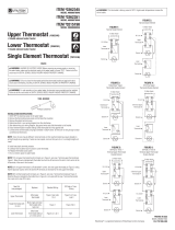
4. Determine which is your wiring diagram from the chart below.
5. After determining your wiring diagram, disconnect wires and slide thermostat out of bracket.
6. Place new thermostat in bracket making SURE thermostat fits firmly against tank.
7. Connect wires to thermostat using figure selected in Step 4 above. (If wires are not long enough, contact
a professional electrician.)
NOTE: Color of wires may be different. Some terminals on this new thermostat may require straight-in wiring
through an eye opening. If wires are now looped, recut and strip wire
3
/8 in. to a straight length and insert.
8. Install new plastic terminal protector.
9. Carefully fold insulation back in place to cover thermostat.
10. Replace thermostat access panel.
11.Turn on electric power to water heater.
New Part
(see packages)
Replaces Standard Wiring
Off Peak or Timer
Wiring
Upper Thermostat
Most upper
thermostats
Figure 2,
see notes 1 & 2
Figure 5 or 6,
see note 3
Single thermostat with
hi-limit
Most single and lower
thermostats with a
high limit
Figure 1 Figure 5 & 6
Lower thermostat
Most lower
thermostats without a
hi-limit control
Figures 2, 3, & 4 N/A
NOTE 1: If old upper thermostat has 8 terminals as in Figure 4, wire new 7 terminal upper thermostat per
Figure 2. Move the wire indicated with the dotted line from the #2 terminal of the old hi-limit control to the
#4 terminal of the new hi-limit control
NOTE 2: If old upper thermostat is a Robertshaw
®
control, wire new upper thermostat per Figure 2 noting
that the physical location of the #2 and the #4 terminals are reversed for the new upper thermostat.
NOTE 3: If old thermostat has 8 terminals as in Figure 6, wire new 7 terminal thermostat per Figure 5.
Note that the wire indicated by the dotted line in Figure 6 is not used with the new 7 terminal thermostat.
Use a wire nut to cap off this wire.
WARNING: This thermostat is factory preset at 120º F. Higher water temperatures increase the
risk of scalds.
To Water Heater
Junction Box
To Water Heater
Junction Box
To Water Heater
Junction Box
To Water Heater
Junction Box
To Water Heater
Junction Box
To Water Heater
Junction Box
Hi-Limit
Hi-Limit
Upper
Thermostat
Lower
Thermostat
Element
Lower
Thermostat
Element
Element
Hi-Limit
8 Terminal Upper
Thermostat
Lower
Thermostat
Element
Element
Hi-Limit
Robertshaw
®
Thermostat
Lower
Thermostat
Element
Element
Hi-Limit
8 Terminal Upper
Thermostat
Lower
Thermostat
Element
Element
Hi-Limit
Hi-Limit
Upper
Thermostat
Lower
Thermostat
Element
Element
Hi-Limit
FIGURE 1:
Normal Single Element
FIGURE 2:
Normal Double Element
FIGURE 3:
Robertshaw
®
Upper
Thermostat Double Element
FIGURE 4:
8 Terminal Upper
Thermostat Double Element
FIGURE 5:
Off Peak or Timer 7
Terminal Upper Thermostat
Double Element
FIGURE 6:
Off Peak or Timer 8
Terminal Upper Thermostat
Double Element
ITEM
#
0362839
MODEL #9008077046
DRAINING TANK
1. Shut off the electric power to the water heater.
2. Shut off the cold water supply to the water heater.
3. Turn on a hot water faucet to relieve the water pressure and leave open to allow draining.
4. Connect a water hose (which terminates to an adequate drain) to the drain valve and open valve (turning
counterclockwise) to allow tank draining.
CAUTION:
After installation of this heating element, to ensure the tank is completely filled, water must be flowing
from a hot water faucet for several minutes before the electricity is turned on to the water heater.
FAILURE TO FOLLOW THIS INSTRUCTION WILL CAUSE DAMAGE TO THE HEATING ELEMENT
AND/OR THE WATER HEATER TANK.
REFILLING THE TANK
1. Close the drain valve (turning clockwise) and turn on the cold water supply to the water heater.
2. Allow all trapped air to escape from the open remote hot water faucet until water has a constant flow.
Then turn the hot water faucet off.
3. Check element for water leaks. If leakage occurs, tighten element or repeat steps 2 through 4 under
“Element Removal”, reposition gasket and reinstall element. Then follow the “Refilling Tank” section.
4. Making sure the thermostat remains firmly against the surface of the tank, reconnect the two wires to
the element.
5. Replace terminal cover on thermostat and fold insulation back in place.
6. Replace access panel.
7. Turn on electric power to water heater.
Garden Hose
Element Wrench
Item
#0159985
1
3
4
1
2
1
3
4
4
1
2
1
2
1
3
4
4
2
1
2
1
3
3
4
4
1
2
1
2
2
1
3
4
4
1
2
1
3
4
1
2
1
3
4
4
3
1
2
1
3
4
1
2
2
ELEMENT REMOVAL/REPLACEMENT
1. Remove the access panel and fold back the insulation.
2. Remove the plastic terminal cover.
3. Disconnect the two wires on the element and using element wrench kit (if screw-in element) unscrew or
unbolt (if bolt-in element) the old element from the tank.
4. Clean the area around the element opening. If you are replacing the lower element, also remove any
sediment from or around the element opening, inside the tank.
5. The element you are replacing is a screw-in type element. Check that the rubber (“O”-ring) gasket is on
the thread side of the element and screw into tank, securing tightly using the element wrench kit.
6. If the element you are replacing is a square flange or round end type element, follow the procedures as
outlined in the ELEMENT ADAPTOR KIT. NOTE: Element adaptor kits are for use with 1 screw-in flange
elements only.
Robertshaw
®
is a registered trademark of Robertshaw Controls Company
/