Broan QP130SS Operating instructions
- Category
- Cooker hoods
- Type
- Operating instructions

MODELS QP130BL • QP130BLC • QP130SS • QP130SSC
QP130WW • QP130WWC • QP136BL • QP136SS • QP136WW
Page 1
WARNING
CAUTION
TO REDUCE THE RISK OF FIRE, ELECTRIC SHOCK, OR IN-
JURY TO PERSONS, OBSERVE THE FOLLOWING:
1. Use this unit only in the manner intended by the manufac-
turer. If you have questions, contact the manufacturer at the
address or telephone number listed in the warranty.
2. Before servicing or cleaning unit, switch power off at service
panel and lock the service disconnecting means to prevent
power from being switched on accidentally. When the ser-
vice disconnecting means cannot be locked, securely fasten
a prominent warning device, such as a tag, to the service
panel.
3. Installation work and electrical wiring (including switch loca-
tion) must be done by a qualified person(s) in accordance
with all applicable codes and standards, including fire-rated
construction.
4. Provide sufficient air for proper combustion and exhausting of
gases through the flue (chimney) of fuel burning equipment
to prevent backdrafting. Follow the combustion equipment
standards such as those published by the National Fire Pro-
tection Association (NFPA), the American Society for Heat-
ing, Refrigeration and Air Conditioning Engineers (ASHRAE),
and local codes.
5. This product may have sharp edges. Be careful to avoid cuts
and abrasions during installation and cleaning.
6. When cutting or drilling into wall or ceiling, do not damage
electrical wiring and other hidden utilities.
7. Ducted fans must always be vented to the outdoors.
8. Use only metal
ductwork.
9. Do not use this fan with any solid-state speed control device.
10. As an alternative, this product may be installed with the UL-
approved cord kit designated for the product, following in-
structions packed with the cord kit.
11. This unit must be grounded.
TO REDUCE THE RISK OF A RANGE TOP GREASE FIRE:
1. Never leave surface units unattended at high settings.
Boilovers cause smoking and greasy spillovers that may ig-
nite. Heat oils slowly on low or medium settings.
2. Always turn hood ON when cooking at high heat or when
cooking flaming foods (i.e. Crepes Suzette, Cherries Jubilee,
Peppercorn Beef Flambé).
3. Clean ventilating fans frequently. Grease should not be al-
lowed to accumulate on fan or filter.
4. Use proper pan size. Always use cookware appropriate for
the size of the surface element.
EVOLUTION
TM
1
QP130, QP136 Series Range Hoods
READ AND SAVE THESE INSTRUCTIONS
FOR DOMESTIC COOKING ONLY
WARNING
TO REDUCE THE RISK OF INJURY TO PERSONS IN THE
EVENT OF A RANGE TOP GREASE FIRE, OBSERVE THE
FOLLOWING:*
1. SMOTHER FLAMES with a close-fitting lid, cookie sheet,
or metal tray, then turn off the burner. BE CAREFUL TO
PREVENT BURNS. If the flames do not go out immediately,
EVACUATE AND CALL THE FIRE DEPARTMENT.
2. NEVER PICK UP A FLAMING PA N — Yo u may be burned or
spread the fire.
3. DO NOT USE WATER, including wet dishcloths or towels -
violent steam explosion will result.
4. Use an extinguisher ONLY if:
A. You know you have a Class ABC extinguisher and you
already know how to operate it.
B. The fire is small and contained in the area where it started.
C. The fire department is being called.
D. You can fight the fire with your back to an exit.
* Based on “Kitchen Fire Safety Tips” published by NFPA.
Installer: Leave this manual with the homeowner.
Homeowner: Cleaning, Maintenance and Operating
instructions on page 2.
NOTE If hood is to be installed non-ducted:
Purchase a set of (2) non-ducted filters from your
local distributor or retailer and attach them to the
aluminum mesh filters.
Register your product online at: www.broan.com/register
1. Fo r indoor use only.
2. For general ventilating use only. Do not use to exhaust haz-
ardous or explosive materials and vapors.
3. To avoid motor bearing damage and noisy and/or unbal-
anced impeller, keep drywall spray, construction dust, etc.,
off power unit.
4. Do not use over cooking equipment greater than 60,000
BTU/hr. as the blower motor will shut down intermittantly.
5. Your hood motor has a thermal overload which will automati-
cally shut off the motor if it becomes overheated. The motor
will restart when it cools down. If the motor continues to shut
off and restart, have the hood serviced.
6. The top of the hood MUST NOT BE LESS than 24” and at a
maximum of 30” above cooktop for best capture of cooking
impurities.
7. This hood is not intended to be used as a shelf.
8. Please read specification label on product for further infor-
mation and requirements.

MODELS QP130BL • QP130BLC • QP130SS • QP130SSC
QP130WW • QP130WWC • QP136BL • QP136SS • QP136WW
Page 2
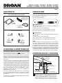
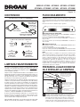
OPERATION
Always turn the hood ON before cooking in order to establish an
air flow in the kitchen. After turning off the range, let the hood run
for a few minutes to clear the air.
Operate the hood as follows:
1 20
1 20
BLOWER SWITCH
This 3-position rocker switch turns blower ON and OFF and
controls blower speed.
Left rocker position (0) turns blower OFF.
Center rocker position (1) turns blower ON to low speed.
Right rocker position (2) turns blower ON to high speed.
LIGHT SWITCH
This 3-position rocker switch turns lights ON and OFF and controls
their intensity.
Left rocker position (0) turns lights OFF.
Center rocker position (1) turns lights ON to low intensity.
Right rocker position (2) turns lights ON to high intensity.
NOTE:
This hood utilizes an offset blower design to achieve greater
performance and lower sound levels. As a result, you may notice
that cooking impurities are more attracted to one side or appear
to be pulled-in faster than they appear on the opposite side. This
is completely normal. The hood has been designed and tested to
provide good capture of cooking impurities and odors under all
normal cooking conditions regardless of the cooking location on the
cooktop. Please note that cooking on the rear burners will always
result in the best capture results, regardless of the hood design.
CLEANING & MAINTENANCE
For performance, appearance, and health reasons, clean filter,
fan and grease-laden surfaces. Use only a clean cloth and mild
detergent solution on stainless and painted surfaces.
Clean all-metal filters in the dishwasher using a non-phosphate
detergent. Discoloration of the filter may occur if using phosphate
detergents, or as a result of local water conditions - but this will
not affect filter performance. This discoloration is not covered by
the warranty.
Clean the non-duct recirculating filter surfaces frequently with
a damp cloth and a mild detergent. DO NOT immerse filters in
water or put in dishwasher. The special “Clean Sense” feature
indicates when the filter is to be replaced. The blue and yellow
strips will blend to green when it is time to change the filter. The
“Clean Sense” feature works best when facing toward the cook-
ing surface. Change the non-duct recirculating filters every 6
months. For replacement non-duct recirculating filters - purchase
S99010353 or Model BPPF30 for 30” hoods, or S99010354 or
Model BPPF36 for 36” hoods.
The motor is permanently lubricated and never needs oiling. If
the motor bearings make excessive or unusual noise, replace
the motor with the exact service motor. The impeller should also
be replaced.
Use 120
V, 35
W, shielded halogen bulbs - MR16 with GU10 base.
Purchase bulbs separately.
CONTENTS
(2)
GREASE
FILTERS
(1) 3¼” X 10”
DAMPER / DUCT
CONNECTOR
(1) 7” ROUND
DUCT
CONNECTOR
(1)
BULB
SUCTION
CUP TOOL
(1) PARTS BAG CONTAINING:
(3)
WIRE
NUTS
INCLUDED WITH THE HOOD:
(9)
#8 X 1/4”
DUCT
CONNECTOR
SCREWS
(5)
#10 X 5/8”
RD. HD.
MOUNTING
SCREWS
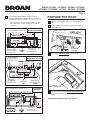
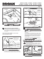
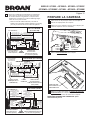
PREPARE HOOD LOCATION
SOFFIT
24" - 30" ABOVE
COOKING SURFACE
CABINET
3¼" X 10" DUCT
(For horizontal discharge)
WALL CAP
ROOF CAP
3¼" X 10" or
7" ROUND DUCT
(For vertical
discharge)
HOUSE WIRING
(Top or Back of hood)
HOODHOOD
1 Determine whether hood will discharge vertically (3¼”
x 10” or 7” Round), or horizontally (3¼” x 10” only). For
vertical or horizontal discharge, run ductwork between
the hood location and a roof cap or wall cap. For best
results, use a minimum number of transitons and elbows.

MODELS QP130BL • QP130BLC • QP130SS • QP130SSC
QP130WW • QP130WWC • QP136BL • QP136SS • QP136WW
Page 3
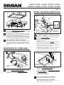
3¼” X 10”
HORIZONTAL DUCTING
CABINET
BOTTOM
CABINET FRONT
HORIZONTAL DUCT
ACCESS HOLE
5¼"
5¼"
HOOD
MOUNTING
SCREWS (5)
ELECTRICAL
ACCESS HOLE
(in wall)
4"
CENTER
LINE
WOOD SHIMS
(recessed-bottom
cabinets only)
14
5
/8" (36" hood)
11
5
/8" (30" hood)
14
5
/8" (36" hood)
11
5
/8" (30" hood)
8½"
1½"
3
/8"
4
7
/
8
"
*
ELECTRICAL
ACCESS HOLE
(in cabinet bottom)
14
5
/8" (36" hood)
2
3
/8"
14
5
/8" (36" hood)
11
5
/8" (30" hood)
11
5
/8" (30" hood)
8½"
10
7
/8"
2
5
/8"
HOOD MOUNTING SCREWS (5)
4
5
/8"
7-IN. ROUND
DUCT
ACCESS
HOLE
7-IN. ROUND
DUCT
ACCESS
HOLE
8" DIA.
HOLE
4
7
/
8
"
*
7-IN. ROUND
DUCTING
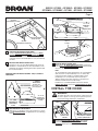
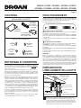
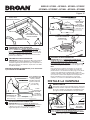
PREPARE THE HOOD
ALUMINUM
FILTERS
5 Remove the Aluminum Filters from the hood.
(2)
LIFT
OUT
(1)
PULL
DOWN
4 Remove all protective polyfilm from the hood (stainless
steel hoods only).
3 Remove parts bag from inside the foam packaging end
cap.
è
è
VERTICAL DUCT
ACCESS HOLE
¾"
10
7
/
8
"
5¼"
5¼"
CENTER
LINE
HOOD MOUNTING SCREWS (5)
ELECTRICAL
ACCESS HOLE
(in cabinet bottom)
WOOD SHIMS
(recessed-bottom
cabinets only)
CABINET FRONT
CABINET
BOTTOM
14
5
/
8
" (36" hood)
4½"
2
3
/
8
"
14
5
/
8
" (36" hood)
11
5
/
8
" (30" hood)
11
5
/
8
" (30" hood)
2
5
/
8
"
4
7
/
8
"
*
8
1
/
2
"
3¼” X 10”
VERTICAL DUCTING
2 Use the proper diagram below, for placement of
ductwork and electrical cutout in cabinet or wall. For a
non-ducted installation, DO NOT cut a duct access hole.
*
Note the extra wood shim and mounting screw near
the cabinet front, 4-7/8” to the right of the cabinet
center line.
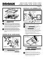
6 Remove 2 screws holding Damper / Duct Connector to
hood. Remove damper/duct connector from inside the
hood.
FOR DUCTED INSTALLATIONS - Skip to Step 9.
DAMPER /
DUCT CONNECTOR

MODELS QP130BL • QP130BLC • QP130SS • QP130SSC
QP130WW • QP130WWC • QP136BL • QP136SS • QP136WW
Page 4
9 DUCTED INSTALLATION ONLY:
Remove 3¼” x 10 vertical, 3¼” x 10” horizontal, or 7-inch
round knockout plate(s) as appropriate for your ducting
method.
10 DUCTED INSTALLATION ONLY:
Attach 3¼” x 10” Damper/Duct Connector (if using 3¼”
x 10” duct) or 7” Round Duct Plate (if using 7-inch round
duct) over the knockout opening.
3¼” X 10”
HORIZONTAL
KNOCKOUT
PLATE
3¼” X 10”
VERTICAL
KNOCKOUT
PLATE
7” ROUND
KNOCKOUT
PLATE (also
remove 3¼” x 10”
vertical plate)
3¼” X 10”
DAMPER /
DUCT
CONNECTOR
7” ROUND
DUCT
PLATE
Note:
To accomodate off-center ductwork, the 3¼” x 10” damper/
duct connector can be installed up to ½” on either side
of the hood center and the 7” round duct plate can be
installed up to ½” on either side of the hood center.
Trim the flange on the duct connector or duct plate if it
interferes with the electrical cable clamp.
Install the 3¼” x 10” Damper/Duct Connector with the
Damper Flap Pivot nearest the Top/Back Edge of Hood.
TOP/BACK
EDGE OF
HOOD
7 NON-DUCTED INSTALLATION ONLY:
Remove Center Retaining Screw and loosen Outer
Retaining Screws holding Recirculation Slide Plate
in place. Pull out slide plate and replace and tighten
retaining screws to hold slide plate in new (non-ducted)
position.
RECIRCULATION
SLIDE PLATE
CENTER
RETAINING SCREW
PULL OUT
8 NON-DUCTED INSTALLATION ONLY:
Purchase a set of (2) non-ducted filters from your local
distributor or retailer. Attach the non-ducted filters to the
aluminum mesh filters following instructions packed with
the non-ducted filters.
FOR NON-DUCTED INSTALLATIONS - Skip to “INSTALL
THE HOOD”.
OUTER
RETAINING SCREWS
è
INSTALL THE HOOD
WARNING
To reduce the risk of electrical shock, switch power off
at service panel. Lock or tag service panel to prevent
power from being switched on accidentally.
ELECTRICAL
WIRING BOX
COVER
11 Remove Electrical Wiring Box Cover from inside
of hood and appropriate Electrical Power Cable
Knockout from top or back of hood.
ELECTRICAL POWER
CABLE KNOCKOUT

MODELS QP130BL • QP130BLC • QP130SS • QP130SSC
QP130WW • QP130WWC • QP136BL • QP136SS • QP136WW
Page 5
CONNECT THE WIRING
15 Connect House Power Cable to range hood wiring -
BLACK to BLACK, WHITE to WHITE, and GREEN or
BARE WIRE to Ground Screw. Replace electrical wiring
box cover.
HOUSE
POWER
CABLE
GROUND
SCREW
12 Run House Power Cable between service panel
and hood location. Attach power cable to hood using
appropriate clamp.
13 Hang hood from (5) mounting screws driven part-way
into cabinet locations (shown in illustrations under
“PREPARE HOOD LOCATION”). Mounting screws are
included in parts bag. Slide hood back towards wall until
mounting screw heads are engaged in narrow end of
keyhole slots in top of hood. Tighten screws securely.
14 DUCTED INSTALLATION ONLY:
Connect ductwork to hood and use duct tape to make
joints secure and air-tight. Make sure the damper / duct
connector enters the ductwork and that the damper
opens and closes freely.
HOUSE
POWER CABLE
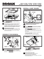
INSTALL LIGHT BULBS
16 Install (4) Halogen Bulbs. Use 120 V, 35 W, shielded
halogen bulbs - MR16 with GU10 base. Purchase bulbs
separately.
NOTE: Suction Cup Tool (included with hood) can be
used to install and remove light bulbs.
Align pins on bulb with large diameter opening on socket,
then push bulb in towards hood and rotate clockwise until
firmly seated.
The position of the bulb socket (depth) is adjustable and
may be necessary when:
a) certain brands of bulbs are difficult to install.
b) the bulb protrudes too far below the light panel.
(1)
PUSH IN
CAUTION: Bulbs may be hot. Refer to bulb
packaging for further information.
(2)
ROTATE
CLOCKWISE
SUCTION
CUP TOOL
HALOGEN
BULB
17 DUCTED INSTALLATION ONLY:
Re-install aluminum filters removed in Step 5.
NON-DUCTED INSTALLATION ONLY:
Install aluminum filters and non-ducted filters - purchased
and assembled in Step 8.
To change the depth of bulb sockets:
- Remove 2 Light Panel Screws. Set screws aside.
- Loosen 2 Screws holding Lamp Socket Bracket to
Light Panel.
- Adjust socket/bracket to desired depth.
- Re-tighten screws securely.
- Re-attach light panel.
LIGHT PANEL
SCREWS
LIGHT PANEL
LAMP SOCKET
BRACKET
SCREWS
LIGHT
PANEL

MODELS QP130BL • QP130BLC • QP130SS • QP130SSC
QP130WW • QP130WWC • QP136BL • QP136SS • QP136WW
Page 6
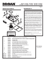
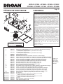
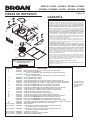
SERVICE PARTS
Order replacement
parts by PA RT NO.
- not by KEY NO.
KEY NO. PART NO. DESCRIPTION
1 97017727 7” Round Duct Plate (includes mounting hardware)
2 97017729 Switch Assembly White (includes 2 switches, nameplate, mounting hardware)
97017730 Switch Assembly Black (includes 2 switches, nameplate, mounting hardware)
3 99526653 Nameplate, White
99526652 Nameplate, Black
4 97017736 Capacitor Kit (includes wire nuts, mounting screw)
5 97017753 Non-duct Slide, White (includes mounting hardware)
97017821 Non-duct Slide, Black (includes mounting hardware)
6 97017755 Light Panel RH White (includes mounting hardware)
97017756 Light Panel RH Black (includes mounting hardware)
97017757 Light Panel RH Stainless (includes mounting hardware)”
7 97017720 Filter Kit for 30”” Hood (2 per bag)
97017721 Filter Kit for 36”” Hood (2 per bag)
8 97017754 Venturi Ring (includes mounting hardware)
9 97017734 Blower Wheel (includes mounting nut)
10 97017732 Motor Kit (includes motor, isolators, mounting hardware)
11 97017728 Damper / Duct Connector (includes mounting hardware)
12 97017758 Light Panel LH White (includes mounting hardware)
97017759 Light Panel LH Black (includes mounting hardware)
97017760 Light Panel LH Stainless (includes mounting hardware)
13 97017731 Lamp Socket (includes lamp socket, wire nuts, mounting screws)
14 97018233 Lamp Socket Bracket (includes mounting hardware)
Not Shown 97017735 Parts Bag
Not Shown 99010353 Non-Duct Filter Kit for 30” Hood (2 charcoal filters and 8 filter clips)
Not Shown 99010354 Non-Duct Filter Kit for 36” Hood (2 charcoal filters and 8 filter clips)
Not Shown 99526707 Suction Cup Tool
Not Shown 97018234 Light Diode (includes wire nuts)
Not Shown 99526798 35W Halogen GU10 Bulb
1
11
2
3
10
12
9
7
4
6
8
13
5
14
Replacement parts can
now be ordered on our
website. Please visit us
at www.broan.com
WARRANTY
One Year Limited Warranty
Broan-NuTone warrants to the original consumer purchaser of its products
that such products will be free from defects in materials or workmanship for a
period of one (1) year from the date of original purchase. THERE ARE NO OTHER
WARRANTIES, EXPRESS OR IMPLIED, INCLUDING, BUT NOT LIMITED TO,
IMPLIED WARRANTIES OF MERCHANTABILITY OR FITNESS FOR A PARTICULAR
PURPOSE.
During this one year period, Broan-NuTone will, at its option, repair or replace,
without charge, any product or part which is found to be defective under normal
use and service. THIS WARRANTY DOES NOT EXTEND TO FLUORESCENT
LAMP STARTERS, TUBES, HALOGEN AND INCANDESCENT BULBS, FUSES,
FILTERS, DUCTS, ROOF CAPS, WALL CAPS AND OTHER ACCESSORIES FOR
DUCTING. This warranty does not cover (a) normal maintenance and service
or (b) any products or parts which have been subject to misuse, negligence,
accident, improper maintenance or repair (other than by Broan-NuTone), faulty
installation or installation contrary to recommended installation instructions.
The duration of any implied warranty is limited to the one year period as specified
for the express warranty. Some states do not allow limitation on how long an
implied warranty lasts, so the above limitation may not apply to you.
BROAN-NUTONE’S OBLIGATION TO REPAIR OR REPLACE, AT BROAN-
NUTONE’S OPTION, SHALL BE THE PURCHASER’S SOLE AND EXCLUSIVE
REMEDY UNDER THIS WARRANTY. BROAN-NUTONE SHALL NOT BE LIABLE
FOR INCIDENTAL, CONSEQUENTIAL OR SPECIAL DAMAGES ARISING OUT OF
OR IN CONNECTION WITH PRODUCT USE OR PERFORMANCE. Some states do
not allow the exclusion or limitation of incidental or consequential damages, so
the above limitation or exclusion may not apply to you. This warranty gives you
specific legal rights, and you may also have other rights, which vary from state to
state. This warranty supersedes all prior warranties.
To qualify for warranty service, you must (a) notify Broan-NuTone at the address
or telephone number below, (b) give the model number and part identification
and (c) describe the nature of any defect in the product or part. At the time of
requesting warranty service, you must present evidence of the original purchase
date.
Broan-NuTone LLC, 926 W. State Street, Hartford, Wisconsin 53027
www.broan.com 800-558-1711
Broan-NuTone Canada, Inc., 1140 Tristar Drive, Mississauga, Ontario Canada
L5T 1H9 www.broan.ca 877-896-1119
Page is loading ...
Page is loading ...
Page is loading ...
Page is loading ...
Page is loading ...
Page is loading ...
Page is loading ...
Page is loading ...
Page is loading ...
Page is loading ...
Page is loading ...
Page is loading ...
Page is loading ...
Page is loading ...
-
 1
1
-
 2
2
-
 3
3
-
 4
4
-
 5
5
-
 6
6
-
 7
7
-
 8
8
-
 9
9
-
 10
10
-
 11
11
-
 12
12
-
 13
13
-
 14
14
-
 15
15
-
 16
16
-
 17
17
-
 18
18
-
 19
19
-
 20
20


Broan QP130SS Operating instructions
- Category
- Cooker hoods
- Type
- Operating instructions
Ask a question and I''ll find the answer in the document
Finding information in a document is now easier with AI
in other languages
- français: Broan QP130SS Mode d'emploi
- español: Broan QP130SS Instrucciones de operación
Related papers
-
Broan BKDEG130BL User manual
-
Broan BCSD136WW Owner's manual
-
-
Broan BCSD130BC Dimensions Guide
-
Broan BKSA130WWADA User manual
-
Broan CLDA136WW User manual
-
-
Broan BPDP136SS User guide
-
-
Other documents
-
NuTone AR130WW User manual
-
-
-
-
NuTone WS1 User manual
-
-
-
Best SMD6 SMD6 Installation Guide 99044540E.pdf
-
-