NuTone WS1 SERIES User manual

Category
Cooker hoods
Type
User manual
Page 1
ALLURE™ WS1 SERIES
RANGE HOOD
!
WARNING
TO REDUCE THE RISK OF FIRE, ELECTRIC SHOCK, OR INJURY TO
PERSONS, OBSERVE THE FOLLOWING:
1. Use this unit only in the manner intended by the manufacturer. If you have
questions, contact the manufacturer at the address or telephone number
listed in the warranty.
2. Before servicing or cleaning unit, switch power off at service panel and
lock the service disconnecting means to prevent power from being
switched on accidentally. When the service disconnecting means cannot
be locked, securely fasten a prominent warning device, such as a tag, to
the service panel.
3. Installation work and electrical wiring must be done by a qualified
person(s) in accordance with all applicable codes and standards, includ-
ing fire-rated construction codes and standards.
4. Sufficient air is needed for proper combustion and exhausting of gases
through the flue (chimney) of fuel burning equipment to prevent backdraft-
ing. Follow the heating equipment manufacturer’s guideline and safety
standards such as those published by the National Fire Protection As-
sociation (NFPA), and the American Society of Heating, Refrigeration and
Air Conditioning Engineers (ASHRAE), and the local code authorities.
5. When cutting or drilling into wall or ceiling, do not damage electrical wiring
and other hidden utilities.
6. To reduce the risk of fire or electric shock, do not use this range hood
with an additional speed control device.
7. Ducted fans must always be vented to the outdoors.
8. To reduce the risk of fire, use only metal ductwork.
9. Use with approved cord-connection kit only.
10.This unit must be grounded.
TO REDUCE THE RISK OF A RANGE TOP GREASE FIRE:
1. Never leave surface units unattended at high settings. Boilovers cause
smoking and greasy spillovers that may ignite. Heat oils slowly on low
or medium settings.
2. Always turn hood ON when cooking at high heat or when cooking flaming
foods.
3. Clean ventilating fans frequently. Grease should not be allowed to
accumulate on fan or filter.
4. Use proper pan size. Always use cookware appropriate for the size of
the surface element.
TO REDUCE THE RISK OF INJURY TO PERSONS IN THE EVENT OF A
RANGE TOP GREASE FIRE, OBSERVE THE FOLLOWING:*
1. SMOTHER FLAMES with a close-fitting lid, cookie sheet, or metal tray,
then turn off the burner. BE CAREFUL TO PREVENT BURNS. If the
flames do not go out immediately, EVACUATE AND CALL THE FIRE
DEPARTMENT.
2. NEVER PICK UP A FLAMING PAN — You may be burned.
3. DO NOT USE WATER, including wet dishcloths or towels - violent steam
explosion will result.
4. Use an extinguisher ONLY if:
A. You know you have a Class ABC extinguisher and you already know
how to operate it.
B. The fire is small and contained in the area where it started.
C. The fire department is being called.
D. You can fight the fire with your back to an exit.
* Based on “Kitchen Fire Safety Tips” published by NFPA.
ALLURE
WS1 SERIES
RANGE HOODS
READ AND SAVE THESE INSTRUCTIONS
Installer: Leave this manual with
the homeowner.
Homeowner: Operating and
Cleaning information on page 5.
Page 1
CAUTION
1. For general ventilating use only. Do not use to exhaust hazardous or
explosive materials and vapors.
2. To avoid motor bearing damage and noisy and/or unbalanced impellers,
keep drywall spray, construction dust, etc. off power unit.
3. For best capture of cooking impurities, your range hood should be
mounted so that the top of the hood is 24-30” above the cooking surface.
4. Please read specification label on product for further information and
requirements.
TABLE OF CONTENTS
This manual is divided into sections as follows:
“PREPARE HOOD LOCATION”
Run ductwork from roof or wall cap, and electrical wiring from service
panel - to installation location
“PREPARE THE HOOD”
Get your hood ready for installation
“CONNECT WIRING”
Make electrical wiring connections to hood
“INSTALL HOOD”
Secure hood to cabinet and ductwork - install bulbs and filters
“OPERATION”
How to use the hood controls
“CLEANING”
Keep your hood in top working condition
“SERVICE PARTS”
Part numbers and exploded view of hood components
“WARRANTY”
One-year limited warranty and how to contact us
NOTE If hood is to be installed Non-Ducted:
Purchase a set of (2) non-ducted filters from your
local distributor or retailer and attach them to the
aluminum mesh filters.
Patent No.:
US D450, 829 S
!
FOR DOMESTIC COOKING ONLY
!
Page 2
ALLURE™ WS1 SERIES
RANGE HOOD
CABINET
BOTTOM
CABINET FRONT
HORIZONTAL DUCT
ACCESS HOLE
5¼"
5¼"
7½"
1
/
8
"
¾"
13
15
/
16
"
(30" hood)
16
15
/
16
"
(36" hood)
13
15
/
16
"
(30" hood)
HOOD
MOUNTING
SCREWS (4)
ELECTRICAL
ACCESS HOLE
(in wall)
3¾"
16
15
/
16
"
(36" hood)
CENTER
LINE
WOOD SHIMS
(recessed-bottom
cabinets only)
19
15
/
16
"
(42" hood)
19
15
/
16
"
(42" hood)
SOFFIT
24" - 30" ABOVE
COOKING SURFACE
CABINET
3¼" X 10" DUCT
(For horizontal discharge)
WALL CAP
ROOF CAP
3¼" X 10"
(For vertical
discharge)
HOUSE WIRING
(Top or Back of hood)
HOODHOOD
PREPARE HOOD LOCATION
PREPARE THE HOOD
1 Remove 7” Round Duct Plate from top of hood. Set duct
plate aside - with mounting screws.
2 Remove tape holding Filters in place. Pull down on filter
tabs and lift filters out. Set filters aside.
7” ROUND
DUCT PLATE
FILTERS
1 Determine whether hood will discharge vertically (3¼” x 10”
or 7” Round), horizontally (3¼” x 10” only) or non-ducted. For
vertical or horizontal discharge, run ductwork between the
hood location and a roof cap or wall cap. For best results, use
a minimum number of transitons and elbows.
2 Use diagrams, below, for proper placement of ductwork and
electrical cutout in cabinet or wall. For a non-ducted installa-
tion, DO NOT cut a duct access hole.
3 Run house wiring between service panel and hood location.
VERTICAL DUCT
ACCESS HOLE
1¼"
1½"
10½"
5¼"
5¼"
CENTER
LINE
HOOD MOUNTING SCREWS (4)
ELECTRICAL
ACCESS HOLE
(in cabinet bottom)
WOOD SHIMS
(recessed-bottom
cabinets only)
CABINET FRONT
CABINET BOTTOM
13
15
/
16
" (30" hood)
16
15
/
16
" (36" hood)
7½"
5"
2"
19
15
/
16
" (42" hood)
13
15
/
16
" (30" hood)
16
15
/
16
" (36" hood)
19
15
/
16
"
(42" hood)
PREPARE HOOD LOCATION
3¼” X 10”
VERTICAL DUCTING
7” ROUND
VERTICAL DUCTING
3¼” X 10”
HORIZONTAL DUCTING
3¼” x 10” or
7” ROUND DUCT
(For vertical discharge)
Page 3
ALLURE™ WS1 SERIES
RANGE HOOD
PREPARE THE HOOD PREPARE THE HOOD
3 Remove
Damper/Duct
Connector from
inside the hood.
Set connec-
tor aside - with
mounting screws
and parts bag.
4 Remove Wir-
ing Cover from
inside the hood.
Set cover and
mounting screw
aside.
5 Remove either
top or back wir-
ing knockout and
install approved
Electrical Cable
Clamp.
DAMPER/DUCT
CONNECTOR
WIRING
COVER
ELECTRICAL CABLE CLAMP
Non-Ducted Installation - Skip to “Connect
Wiring” section.
6 Remove Light Panel - held in place with (3) #8 screws
and (2) #8 screws. Disconnect light assembly wire harness
(white connector).
(3) #8 SCREWS
LIGHT
PANEL
(2) #8 SCREWS
The following
Steps (6 thru
13) are for
DUCTED
INSTALLATION
ONLY.
BAFFLE
7 Remove Air
Chute - held in
place with one
(1) screw.
NOTE: Be care-
ful not to discon-
nect any wires.
9 Rotate baffle. Re-
insert baffle into air
chute (as shown) so
that baffle tabs fit all
the way into slots in
air chute. An audible
“click” will be heard
when fully installed.
This will close off
the air flow through
the non-ducted slots
on top of hood.
10
Re-install air chute, re-connect wire
harness, and replace light panel.
NOTE: Be careful not to trap wires
between support fin and light panel.
AIR CHUTE
SLOTS
8 Remove Baffle
from air chute.
BAFFLE
SUPPORT FIN
TABS
Page 4
ALLURE™ WS1 SERIES
RANGE HOOD
CONNECT WIRING
WARNING: To reduce the risk of electric shock,
make sure power is switched off at the service
panel. Lock or tag service panel to prevent power
from being switched on accidentally.
HOUSE
WIRING
(120 VAC)
CARDBOARD
(Use to protect
cooktop)
1 Connect House Wiring (120 VAC) to hood. Use a piece of
Cardboard to protect the cooktop, if necessary.
2 Connect house black to hood black wire, house white to hood
white wire, and house ground under Green Ground Screw.
Securely tighten cable clamp onto house wiring.
GREEN
GROUND
SCREW
3 Replace wiring cover.
PREPARE THE HOOD
11 Remove appropriate Duct Knockout(s) from top or back of
hood.
REAR
RECTANGULAR
DUCT KNOCKOUT
(Remove for 3¼” x 10”
Horizontal Discharge)
TOP RECTANGULAR
DUCT KNOCKOUT
(Remove for 3¼” x 10”
Vertical & for 7” Round
Discharge)
SEMI-CIRCULAR
DUCT KNOCKOUT
(Remove for 7” Round
Discharge)
13
7” Round Ducted Discharge Only: Re-install 7” Round Duct
Plate removed in Step #1 under “PREPARE THE HOOD”
section. Install a 7” round damper (purchase separately).
Damper flap must open freely in direction of air flow (away
from range hood).
12
x 10” Ducted Discharge Only: Attach Damper/Duct
Connector over knockout opening. Make sure damper Pivot
is nearest to Top/Back Edge of hood. Remove Tape from
damper flap.
DAMPER/DUCT
CONNECTOR
(Vertical discharge
position shown)
TAPE
UP TO 1”
SIDE-TO-SIDE
ADJUSTMENT
PIVOT
TOP/BACK
EDGE
NOTE
To accomodate off-center ductwork, the Damper/Duct
Connector can be installed up to 1-inch on either side of
hood center or the 7” Round Duct Plate can be installed
up to ½” on either side of hood center. In extreme off-center
installations, one end of the duct connector may need to be trimmed
to clear the electrical cable clamp.
Ú
Page 5
ALLURE™ WS1 SERIES
RANGE HOOD
WARNING: To reduce the risk of electric shock,
disconnect from power supply before cleaning.
Aluminum mesh filters: Clean frequently using hot water and a
mild detergent. Filters are dishwasher safe.
Charcoal filters: Clean filter surfaces frequently with a damp cloth
and a mild detergent. DO NOT immerse filters in water or put in
dishwasher. The special “Clean Sense feature indicates when the
filter is to be replaced. The blue and yellow strips will blend to green
when it is time to change the filter. The “Clean Sensefeature works
best when facing toward the cooking surface.
To clean hood: Remove filters. Use a damp cloth and a mild deter-
gent to wipe all grease-laden surfaces. Use care when cleaning fan
blade - it must not become bent or misaligned. DO NOT ALLOW
WATER TO ENTER MOTOR. Make sure all surfaces are completely
dry before re-installing filters and restoring power.
Motor is permanently lubricated. Do not oil or disassemble motor.
OPERATION
CLEANING
Fan: The 3-position rocker switch (on the left) controls the fan. The
left position is low speed, center position is off, and right position is
high speed. An indicator light shows that the fan is on.
Light: The 3-position rocker switch (on the right) controls the lights.
The left position is low light intensity, center position is off, and right
position is high light intensity.
INSTALL HOOD
KEYHOLE
(4)
MOUNTING
SCREW
(4)
1 Hang hood from (4) Mounting Screws (from parts bag).
Slide hood towards wall until mounting screws are engaged
in narrow end of (4) Keyholes. Tighten mounting screws
securely.
PAR20,
50W MAX.
HALOGEN
BULB (2)
- or -
R16,
40W MAX.
INCANDESCENT
BULB (2)
4 Replace filters and make sure fan blade turns freely. Turn on
power at service panel, and test for proper operation.
2 Connect ductwork to hood. Use Duct Tape to make joints
secure and air tight.
DUCT
TAPE
CAUTION DO NOT PUSH ON FAN BLADE. Pushing on the
blade may cause it to interfere with other hood parts.
3 Install (2) PAR20, 50 W Maximum Halogen Bulbs or (2)
R16, 40 W Maximum Incandescent Bulbs. Purchase bulbs
separately.
!
CAUTION: Bulbs may be hot! Refer to bulb packaging
for further information.
If hood is to be installed Non-Ducted:
Purchase a set of (2) non-ducted filters from your local distributor or
retailer and attach them to the aluminum mesh filters.
NON-DUCTED FILTERS
Page 6
ALLURE™ WS1 SERIES
RANGE HOOD
626976D
WARRANTY
NUTONE ONE YEAR LIMITED WARRANTY
NuTone warrants to the original consumer purchaser of its products that such
products will be free from defects in materials or workmanship for a period of one
year from the date of original purchase. THERE ARE NO OTHER WARRANTIES,
EXPRESS OR IMPLIED, INCLUDING, BUT NOT LIMITED TO, IMPLIED WAR-
RANTIES OF MERCHANTABILITY OR FITNESS FOR A PARTICULAR PURPOSE.
During this one-year period, NuTone will, at its option, repair or replace, without
charge, any product or part which is found to be defective under normal use
and service.
THIS WARRANTY DOES NOT EXTEND TO FLUORESCENT LAMP STARTERS AND
TUBES. This warranty does not cover (a) normal maintenance and service or (b)
any products or parts which have been subject to misuse, negligence, accident,
improper maintenance or repair (other than by NuTone), faulty installation or
installation contrary to recommended installation instructions.
The duration of an implied warranty is limited to the one-year period as specified
for the express warranty. Some states do not allow limitation on how long an
implied warranty lasts, so the above limitation may not apply to you.
NUTONE’S OBLIGATION TO REPAIR OR REPLACE, AT NUTONE’S OPTION, SHALL
BE THE PURCHASER’S SOLE AND EXCLUSIVE REMEDY UNDER THIS WAR-
RANTY. NUTONE SHALL NOT BE LIABLE FOR INCIDENTAL, CONSEQUENTIAL
OR SPECIAL DAMAGES ARISING OUT OF OR IN CONNECTION WITH PRODUCT
USE OR PERFORMANCE. Some states do not allow the exclusion or limitation of
incidental or consequential damages, so the above limitation may not apply to you.
This warranty gives you specific legal rights, and you may also have other rights,
which vary from state to state. This warranty supersedes all prior warranties.
To qualify for warranty service, you must (a) notify NuTone at the address or
telephone number below, (b) give the model number and part identification and
(c) describe the nature of any defect in the product or part. At the time of request-
ing warranty service, you must present evidence of the original purchase date.
NuTone, Inc., 4820 Red Bank Road, Cincinnati, OH 45227 (1-800-543-8687)
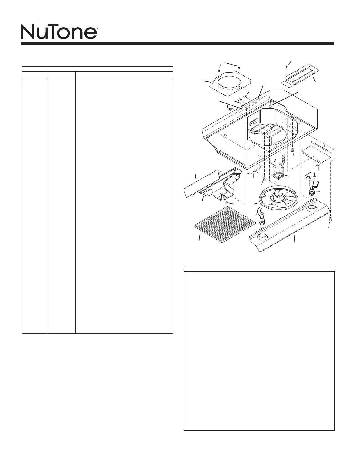
SERVICE PARTS
KEY NO. PART NO. DESCRIPTION
1 R680508 7” Round Duct Plate (includes hardware)
2 R740013 Damper/Duct Connector (includes hardware)
3 R602017 Screw, #8-18 x ¼ Hex* (2 in package)
4 R561115 Rocker Switch, Almond (2 in package)
R561116 Rocker Switch, White (2 in package)
R561117 Rocker Switch, Black (2 in package)
R561119 Rocker Switch, Biscuit (2 in package)
5 R627518 Nameplate, White
R627519 Nameplate, Almond
R627520 Nameplate, Stainless
R627533 Nameplate, Biscuit
R627579 Nameplate, Black
6 R607657 Lens
7 R602534 Screw, 8-18 x 3/8* (2 in package)
8 R602533 Ground Screw (2 req.)
9 R680504 Wiring Cover (includes hardware)
10 * Rivet, Pop .125 dia.
11 R169016 Filter Spring Kit
12 R169002 Motor Mounting Screw (3 each part)
13 R99080535 Motor (includes Motor Mounting Kit)
14 R401647 Air Chute Assembly
(includes Key No. 15 & hardware)
15 R401646 Baffle
16 R531075 Fan Blade (Includes hairpin clip)
** R99420635 Hairpin Clip
17 99010299 Filter Kit, for 30” Hood (2 per bag)
99010300 Filter Kit, for 36” Hood (2 per bag)
99010301 Filter Kit, for 42” Hood (2 per bag)
18 R111630 Lamp Socket Harness
19 R7201731 Light Panel, White, for 30” Hood
R7201751 Light Panel, White, for 36” Hood
R7201771 Light Panel, White, for 42” Hood
R7201732 Light Panel, Almond, for 30” Hood
R7201752 Light Panel, Almond, for 36” Hood
R7201772 Light Panel, Almond, for 42” Hood
R7201734 Light Panel, Black, for 30” Hood
R7201754 Light Panel, Black, for 36” Hood
R7201774 Light Panel, Black, for 42” Hood
R720174 Light Panel, Stainless, for 30” Hood
R720176 Light Panel, Stainless, for 36” Hood
R720178 Light Panel, Stainless, for 42” Hood
R7201735 Light Panel, Biscuit, for 30” Hood
R7201755 Light Panel, Biscuit, for 36” Hood
R7201775 Light Panel, Biscuit, for 42” Hood
20 R169004 Indicator Light (includes 2 wire nuts and lens)
** R169010 Light Diode Assembly (includes wire nut)
** R111626 Wire Harness
** 99010308 Non-Ducted Filter Kit, 30” (2 per bag)
** 99010309 Non-Ducted Filter Kit, 36” (2 per bag)
** 99010310 Non-Ducted Filter Kit, 42” (2 per bag)
Order replacement parts by PART NO. - not by KEY NO.
* Standard hardware - may be purchased locally.
** Not illustrated.
1
2
3
5
6
9
10
11
13
14
8
4
16
17
3
18
7
19
3
12
20
7
7
15
  • Page 1 1
  • Page 2 2
  • Page 3 3
  • Page 4 4
  • Page 5 5
  • Page 6 6
  • Page 7 7
  • Page 8 8
  • Page 9 9
  • Page 10 10
  • Page 11 11
  • Page 12 12

NuTone WS1 SERIES User manual

Category
Cooker hoods
Type
User manual

Ask a question and I''ll find the answer in the document

Finding information in a document is now easier with AI

in other languages