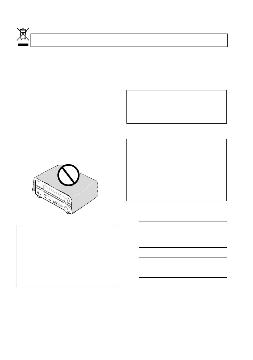
Pioneer VSX-916-K User manual

Category
AV receivers
Type
User manual

This manual is also suitable for

SINTOAMPLIFICATORE AUDIO/VIDEO
MULTICANALE
Operating Instructions
Istruzioni per l’uso
Discover the benefits of registering your product online at www.pioneer.co.uk
(www.pioneer-eur.com).
VSX-916-S/-K
AUDIO/VIDEO MULTI-CHANNEL RECEIVER
Registra il tuo prodotto su www.pioneer.it (o www.pioneer-eur.com)
e scopri subito quali vantaggi puoi ottenere!
VSX_916.book.fm 1 ページ 2005年12月22日 木曜日 午後4時21分
Replacement and mounting of an AC plug on the power supply cord of this unit should be performed only by qualified
service personnel.
D3-4-2-1-2-2_B_En
IMPORTANT: THE MOULDED PLUG
This appliance is supplied with a moulded three pin mains plug for your safety and convenience. A 5 amp fuse is fitted in this plug. Should the
fuse need to be replaced, please ensure that the replacement fuse has a rating of 5 amps and that it is approved by ASTA or BSI to BS1362.
Check for the ASTA mark or the BSI mark on the body of the fuse.
If the plug contains a removable fuse cover, you must ensure that it is refitted when the fuse is replaced. If you lose the fuse cover the plug
must not be used until a replacement cover is obtained. A replacement fuse cover can be obtained from your local dealer.
If the fitted moulded plug is unsuitable for your socket outlet, then the fuse shall be removed and the plug cut off and disposed of
safely. There is a danger of severe electrical shock if the cut off plug is inserted into any 13 amp socket.
If a new plug is to be fitted, please observe the wiring code as shown below. If in any doubt, please consult a qualified electrician.
IMPORTANT: The wires in this mains lead are coloured in accordance with the following code:
Blue : Neutral Brown : Live
As the colours of the wires in the mains lead of this appliance may not correspond with the coloured markings identifying the terminals in
your plug, proceed as follows ;
The wire which is coloured BLUE must be connected to the terminal which is marked with the
letter N or coloured BLACK.
The wire which is coloured BROWN must be connected to the terminal which is marked with the
letter L or coloured RED.
How to replace the fuse: Open the fuse compartment with a screwdriver and replace the fuse.
Thank you for buying this Pioneer product.
Please read through these operating instructions so
you will know how to operate your model properly.
After you have finished reading the instructions, put
them away in a safe place for future reference.
The exclamation point within an equilateral
triangle is intended to alert the user to the
presence of important operating and
maintenance (servicing) instructions in the
literature accompanying the appliance.
The lightning flash with arrowhead symbol,
within an equilateral triangle, is intended to
alert the user to the presence of uninsulated
"dangerous voltage" within the product's
enclosure that may be of sufficient
magnitude to constitute a risk of electric
shock to persons.
CAUTION:
TO PREVENT THE RISK OF ELECTRIC
SHOCK, DO NOT REMOVE COVER (OR
BACK). NO USER-SERVICEABLE PARTS
INSIDE. REFER SERVICING TO QUALIFIED
SERVICE PERSONNEL.
CAUTION
RISK OF ELECTRIC SHOCK
DO NOT OPEN
IMPORTANT
D3-4-2-1-1_En-A
WARNING
This equipment is not waterproof. To prevent a fire
or shock hazard, do not place any container filed
with liquid near this equipment (such as a vase or
flower pot) or expose it to dripping, splashing, rain
or moisture.
D3-4-2-1-3_A_En
WARNING
The voltage of the available power supply differs
according to country or region. Be sure that the
power supply voltage of the area where this unit
will be used meets the required voltage (e.g., 230V
or 120V) written on the rear panel.
D3-4-2-1-4_A_En
Before plugging in for the first time, read the following
section carefully.
WARNING
To prevent a fire hazard, do not place any naked
flame sources (such as a lighted candle) on the
equipment.
D3-4-2-1-7a_A_En
Operating Environment
Operating environment temperature and humidity:
+5 ºC – +35 ºC (+41 ºF – +95 ºF); less than 85 %RH
(cooling vents not blocked)
Do not install this unit in a poorly ventilated area, or in
locations exposed to high humidity or direct sunlight (or
strong artificial light)
D3-4-2-1-7c_A_En
This product complies with the Low Voltage Directive
(73/23/EEC, amended by 93/68/EEC), EMC Directives
(89/336/EEC, amended by 92/31/EEC and
93/68/EEC).
D3-4-2-1-9a_En
VSX_916.book.fm 2 ページ 2005年12月22日 木曜日 午後4時21分
VENTILATION CAUTION
When installing this unit, make sure to leave space
around the unit for ventilation to improve heat
radiation (at least 60 cm at top, 10 cm at rear, and
30 cm at each side).
WARNING
Slots and openings in the cabinet are provided for
ventilation to ensure reliable operation of the
product, and to protect it from overheating. To
prevent fire hazard, the openings should never be
blocked or covered with items (such as newspapers,
table-cloths, curtains) or by operating the
equipment on thick carpet or a bed.
D3-4-2-1-7b_A_En
This product is for general household purposes. Any
failure due to use for other than household purposes
(such as long-term use for business purposes in a
restaurant or use in a car or ship) and which
requires repair will be charged for even during the
warranty period.
K041_En
If the AC plug of this unit does not match the AC
outlet you want to use, the plug must be removed
and appropriate one fitted. Replacement and
mounting of an AC plug on the power supply cord of
this unit should be performed only by qualified
service personnel. If connected to an AC outlet, the
cut-off plug can cause severe electrical shock. Make
sure it is properly disposed of after removal.
The equipment should be disconnected by removing
the mains plug from the wall socket when left
unused for a long period of time (for example, when
on vacation).
D3-4-2-2-1a_A_En
CAUTION
The STANDBY/ON switch on this unit will not
completely shut off all power from the AC outlet.
Since the power cord serves as the main disconnect
device for the unit, you will need to unplug it from
the AC outlet to shut down all power. Therefore,
make sure the unit has been installed so that the
power cord can be easily unplugged from the AC
outlet in case of an accident. To avoid fire hazard,
the power cord should also be unplugged from the
AC outlet when left unused for a long period of time
(for example, when on vacation).
D3-4-2-2-2a_A_En
D
O
W
N
D
O
W
N
Manufactured under license from Dolby
Laboratories. "Dolby", "Pro Logic",
"Surround EX", and the double-D symbol
are trademarks of Dolby Laboratories.
"DTS" ,"DTS-ES" ,"DTS 96/24" and
"Neo:6" are trademarks of Digital Theater
Systems, Inc.
If you want to dispose this product, do not mix it with general household waste. There is a separate collection system for used
electronic products in accordance with legislation that requires proper treatment, recovery and recycling.
Private households in the 25 member states of the EU, in Switzerland and Norway may return their used electronic products free of charge to
designated collection facilities or to a retailer (if you purchase a similar new one).
For countries not mentioned above, please contact your local authorities for the correct method of disposal.
By doing so you will ensure that your disposed product undergoes the necessary treatment, recovery and recycling and thus prevent potential
negative effects on the environment and human health.
K058_En
WARNING
Do not use or store batteries in direct sunlight or
other excessively hot place, such as inside a car or
near a heater. This can cause batteries to leak,
overheat, explode or catch fire. It can also reduce the
life or performance of batteries.
D3-4-2-3-3_En
VSX_916.book.fm 3 ページ 2005年12月22日 木曜日 午後4時21分
Contents
01 Before you start
Checking what’s in the box
. . . . . . . . . . . . . . . 6
Loading the batteries
. . . . . . . . . . . . . . . . . . . 6
Installing the receiver
. . . . . . . . . . . . . . . . . . . 6
Ventilation
. . . . . . . . . . . . . . . . . . . . . . . . . . . . 6
02 5 minute guide
Introduction to home theater
. . . . . . . . . . . . . 7
Listening to Surround Sound
. . . . . . . . . . . . . 7
Using the Quick Setup
. . . . . . . . . . . . . . . . . . 8
03 Quick surround sound setup
Automatically setting up for surround sound
(MCACC)
. . . . . . . . . . . . . . . . . . . . . . . . . . . . . 9
Other problems when using the Auto
MCACC Setup
. . . . . . . . . . . . . . . . . . . . . . 11
04 Connecting up
Making cable connections
. . . . . . . . . . . . . . 12
Analog audio cables
. . . . . . . . . . . . . . . . . . 12
Digital audio cables
. . . . . . . . . . . . . . . . . . 12
Video cables
. . . . . . . . . . . . . . . . . . . . . . . . 12
Connecting a DVD player and TV
. . . . . . . . . 13
Connecting the multichannel analog
outputs
. . . . . . . . . . . . . . . . . . . . . . . . . . . . 14
Connecting a satellite receiver or other
digital set-top box
. . . . . . . . . . . . . . . . . . . . . 14
Connecting other audio components
. . . . . . 15
About the WMA9 Pro decoder
. . . . . . . . . . 15
Connecting other video components
. . . . . . 16
Using the component video jacks
. . . . . . . . 17
Connecting to the front panel video
terminal
. . . . . . . . . . . . . . . . . . . . . . . . . . . 17
Connecting antennas
. . . . . . . . . . . . . . . . . . 18
Using external antennas
. . . . . . . . . . . . . . . 18
Connecting the speakers
. . . . . . . . . . . . . . . 19
Hints on speaker placement
. . . . . . . . . . . . 20
05 Controls and displays
Front panel
. . . . . . . . . . . . . . . . . . . . . . . . . . 22
Display
. . . . . . . . . . . . . . . . . . . . . . . . . . . . . 23
Remote control
. . . . . . . . . . . . . . . . . . . . . . . 25
Operating range of remote control
. . . . . . . 27
06 Listening to your system
Auto playback
. . . . . . . . . . . . . . . . . . . . . . . . 28
Listening in surround sound
. . . . . . . . . . . . . 28
Using the Advanced surround effects
. . . . 29
Setting the effect options
. . . . . . . . . . . . . . 29
Listening in stereo
. . . . . . . . . . . . . . . . . . . . . 30
Listening with Acoustic Calibration EQ
. . . . . 30
Using surround back channel processing
. . . 31
Using Virtual Surround Back (VSB)
. . . . . . . 31
Using Midnight and Loudness
. . . . . . . . . . . . 32
Using the Sound Retriever
. . . . . . . . . . . . . . . 32
Enhancing dialog
. . . . . . . . . . . . . . . . . . . . . 32
Using the tone controls
. . . . . . . . . . . . . . . . . 32
Playing other sources
. . . . . . . . . . . . . . . . . . 33
Choosing the input signal
. . . . . . . . . . . . . . . 33
Selecting the multichannel analog inputs
. . . 33
07 USB playback
Using the USB interface
. . . . . . . . . . . . . . . . 34
Basic playback controls
. . . . . . . . . . . . . . . . . 34
Compressed audio compatibility
. . . . . . . . . 35
08 The System Setup menu
Making receiver settings from the System
Setup menu. . . . . . . . . . . . . . . . . . . . . . . . . . 36
Surround back speaker setting . . . . . . . . . . . 36
Manual MCACC speaker setup . . . . . . . . . . . 37
Fine Channel Level . . . . . . . . . . . . . . . . . . . 38
Fine Speaker Distance . . . . . . . . . . . . . . . . 38
Acoustic Calibration EQ . . . . . . . . . . . . . . . 39
Manual speaker setup . . . . . . . . . . . . . . . . . . 41
Speaker Setting . . . . . . . . . . . . . . . . . . . . . 42
Crossover Network . . . . . . . . . . . . . . . . . . . 43
Channel Level . . . . . . . . . . . . . . . . . . . . . . . 43
Speaker Distance . . . . . . . . . . . . . . . . . . . . 44
09 Using the tuner
Listening to the radio. . . . . . . . . . . . . . . . . . . 45
Improving FM stereo sound . . . . . . . . . . . . 45
Tuning directly to a station . . . . . . . . . . . . . 45
Saving station presets . . . . . . . . . . . . . . . . . . 46
Naming station presets. . . . . . . . . . . . . . . . 46
Listening to station presets. . . . . . . . . . . . . 46
An introduction to RDS . . . . . . . . . . . . . . . . . 47
Displaying RDS information . . . . . . . . . . . . 47
Searching for RDS programs . . . . . . . . . . . 47
Using EON . . . . . . . . . . . . . . . . . . . . . . . . . . 48
10 Making recordings
Making an audio or a video recording . . . . . . 49
VSX_916.book.fm 4 ページ 2005年12月22日 木曜日 午後4時21分
English Italiano Français
Nederlands
EspañolDeutsch
11 Controlling the rest of your
system
Operating other Pioneer components
. . . . . . 50
Setting the remote to control other
components
. . . . . . . . . . . . . . . . . . . . . . . . . 50
Selecting preset codes directly
. . . . . . . . . . . 51
Programming signals from other remote
controls
. . . . . . . . . . . . . . . . . . . . . . . . . . . . . 51
Erasing one of the remote control button
settings
. . . . . . . . . . . . . . . . . . . . . . . . . . . . . 52
Erasing all of the remote control presets
. . . . 53
Direct function
. . . . . . . . . . . . . . . . . . . . . . . 53
Confirming preset codes
. . . . . . . . . . . . . . . . 53
Multi Operation and System Off
. . . . . . . . . . 53
Programming a multi-operation or a
shutdown sequence
. . . . . . . . . . . . . . . . . . 54
Using multi operations
. . . . . . . . . . . . . . . . 55
Using System off
. . . . . . . . . . . . . . . . . . . . . 55
Controls for TVs
. . . . . . . . . . . . . . . . . . . . . . . 55
Controls for other components
. . . . . . . . . . . 57
12 Other connections
Second Zone speaker B setup
. . . . . . . . . . . . 59
Switching the speaker system
. . . . . . . . . . 59
Bi-amping your front speakers
. . . . . . . . . . . 60
Bi-wiring your speakers
. . . . . . . . . . . . . . . . . 60
Connecting additional amplifiers
. . . . . . . . . . 61
Using this receiver with a Pioneer plasma
display
. . . . . . . . . . . . . . . . . . . . . . . . . . . . . . 61
Using the SR+ mode with a Pioneer
plasma display
. . . . . . . . . . . . . . . . . . . . . . 62
13 Other Settings
The Input Assign menu
. . . . . . . . . . . . . . . . . 63
The Other Setup menu
. . . . . . . . . . . . . . . . . 64
Dynamic Range Control Setup
. . . . . . . . . . 64
Dual Mono Setup
. . . . . . . . . . . . . . . . . . . . 65
LFE Attenuator Setup
. . . . . . . . . . . . . . . . . 65
SR+ Setup for Pioneer plasma displays
. . . 65
14 Additional information
Troubleshooting
. . . . . . . . . . . . . . . . . . . . . . 66
Resetting the main unit
. . . . . . . . . . . . . . . . . 68
Switching the speaker impedance
. . . . . . . . . 68
Changing the TV format setting
. . . . . . . . . . . 68
Specifications
. . . . . . . . . . . . . . . . . . . . . . . . 69
Power cord caution
. . . . . . . . . . . . . . . . . . . . 70
Cleaning the unit
. . . . . . . . . . . . . . . . . . . . . . 70
VSX_916.book.fm 5 ページ 2005年12月22日 木曜日 午後4時21分
Before you start01
6
En
Chapter 1:
Before you start
Checking what’s in the box
Please check that you've received the following
supplied accessories:
Setup microphone
Remote control unit
Dry cell batteries (AA size IEC R6) x2
AM loop antenna
FM wire antenna
Warranty card
These operating instructions
Loading the batteries
Caution
Incorrect use of batteries may result in such
hazards as leakage and bursting. Observe the
following precautions:
Never use new and old batteries together.
Insert the plus and minus sides of the
batteries properly according to the marks
in the battery case.
Batteries with the same shape may have
different voltages. Do not use different
batteries together.
When disposing of used batteries, please
comply with governmental regulations or
environmental public instruction’s rules
that apply in your country/area.
WARNING
Do not use or store batteries in direct
sunlight or other excessively hot place,
such as inside a car or near a heater. This
can cause batteries to leak, overheat,
explode or catch fire. It can also reduce the
life or performance of batteries.
Installing the receiver
When installing this unit, make sure to put it on
a level and stable surface. Don’t install it on the
following places:
– on a color TV (the screen may distort)
– near a cassette deck (or close to a device that
gives off a magnetic field). This may interfere
with the sound.
– in direct sunlight
– in damp or wet areas
– in extremely hot or cold areas
– in places where there is vibration or other
movement
– in places that are very dusty
– in places that have hot fumes or oils (such as
a kitchen)
Ventilation
When installing this unit, make sure to leave
space around the unit for ventilation to
improve heat dispersal (at least 20 cm at the
top). If not enough space is provided between
the unit and walls or other equipment, heat will
build up inside, interfering with performance
and/or causing malfunctions.
Slot and openings in the cabinet are provided
for ventilation and to protect the equipment
from overheating. To prevent fire hazard, do not
place anything directly on top of the unit, make
sure the openings are never blocked or covered
with items (such as newspapers, table-cloths
and curtains), and do not operate the
equipment on thick carpet or a bed.
01_before_you_start.fm 6 ページ 2005年12月26日 月曜日 午前11時8分
5 minute guide
02
7
En
English
Français
Deutsch
Nederlands
Italiano
Español
Chapter 2:
5 minute guide
Introduction to home theater
Home theater refers to the use of multiple
audio tracks to create a surround sound effect,
making you feel like you're in the middle of the
action or concert. The surround sound you get
from a home theater system depends not only
on your speaker setup, but also on the source
and the sound settings of the receiver.
This receiver will automatically decode
multichannel Dolby Digital, DTS, or Dolby
Surround sources according to your speaker
setup. In most cases, you won’t have to make
changes for realistic surround sound, but
other possibilities (like listening to a CD with
multichannel surround sound) are explained in
Listening to your system
on page 28.
Listening to Surround Sound
With the following quick setup guide, you
should have your system hooked up for
surround sound in no time at all. In most
cases, you can simply leave the receiver in the
default settings.
Be sure to complete all connections before
connecting to an AC power source.
1 Connect your DVD player and TV.
See
Connecting a DVD player and TV
on page 13
to do this. For surround sound, you’ll want to
hook up using a digital connection from the
DVD player to the receiver.
2 Connect your speakers and place them for
optimal surround sound.
See
Connecting the speakers
on page 19.
Where you place the speakers will have a big
effect on the sound. Place your speakers as
shown below for the best surround sound
effect. Also see
Hints on speaker placement
on
page 20 for more on this.
3 Plug in and switch on the receiver, followed
by your DVD player, subwoofer and TV.
Make sure you’ve set the video input on your TV
to this receiver. Check the manual that came
with the TV if you don’t know how to do this.
4 Press QUICK SETUP on the front panel to
specify your speaker setup, room size and
listening position.
Use the
MULTI JOG
dial to select and
ENTER
to confirm your selection. See
Using the Quick
Setup
below for more on this.
5 Play a DVD, and adjust the volume.
Make sure that
DVD
is showing in the
receiver’s display. If it isn’t, press
DVD
on the
remote to set the receiver to the DVD input.
1
There are several other sound options you can
select. See
Listening to your system
on page 28
for more on this.
2
Note
1 You may need to set your DVD player to output Dolby Digital, DTS and 88.2/96 kHz PCM (2 channel) audio (see your DVD play-
er’s manual for more on this).
2 Depending on your DVD player or source disc, you may only get 2 channel sound. In this case, the listening mode must be set
to
STANDARD
(see
Listening in surround sound
on page 28 if you need to do this) if you want multichannel surround sound.
Front
speaker
(L)
Surround
speaker (LS)
Surround
speaker (RS)
Surround back
speaker (SBL)
Surround
back
speaker (SBR)
Center
speaker
(C)
Subwoofer (SW)
Listening
position
Front
speaker
(R)
VSX_916.book.fm 7 ページ 2005年12月22日 木曜日 午後4時21分
5 minute guide02
8
En
Using the Quick Setup
You can use the Quick Setup to get your
system up and running with just a few button
presses. The receiver automatically makes the
necessary settings after you have selected your
speaker setup, room size and listening
position. Use the front panel controls for the
steps below.
If you want a more complete setup option,
refer to
Automatically setting up for
surround sound (MCACC)
on page 9. If you
choose to do so, you can skip the Quick
Setup.
1
1 If the receiver is off, press
STANDBY/ON
to turn the power on.
2 Press
QUICK SETUP
.
SW DET
flashes in the display while the
receiver checks your setup for a subwoofer.
SW YES
or
SW NO
confirms the subwoofer
check, then the display prompts you to
select your speaker setup.
3 Use the
MULTI JOG
dial to choose your
speaker setup.
When a subwoofer was detected in step 2, the
following choices are available:
2.1ch – 3.1ch – 4.1ch – 5.1ch – 6.1ch – 7.1ch
If a subwoofer wasn’t detected in step 2, you
can cycle between the following choices:
2.0ch – 3.0ch – 4.0ch – 5.0ch – 6.0ch – 7.0ch
Check the table below to find the speaker
setup that corresponds with your system.
4 Press
ENTER
.
5 Use the
MULTI JOG
dial to choose your
room size.
Depending on the distance of your speakers
from the listening position, choose between
small, medium, or large (
S
,
M
or
L
),
M
being an
average-sized room.
6 Press
ENTER
.
7 Use the
MULTI JOG
dial to choose your
listening position.
You can cycle between the following choices:
FWD
– If you are nearer to the front
speakers than the surround speakers
MID
– If you are equal distance from the
front and surround speakers
BACK
– If you are nearer to the surround
speakers than the front speakers
8 Press
ENTER
to confirm your setup.
The display shows the speaker setup, room size
and listening position that you have selected.
Note
1 See also
Making receiver settings from the System Setup menu
on page 36 for more setup options.
STANDBY/ON
PHONES
DVD/ LD
TV/SAT DVR/VCR
STANDARD
MIDNIGHT/
LOUDNESS
ADVANCED
SURR
ST/DIRECT/
AUTO SURR
LISTENING
MODE
QUICK
SETUP
SETUP
TUNING/
STATION
TONE
PTY
SEARCH
SPEAKERS
TUNER
EDIT
EON
MODE
MULTI JOG
DIGITAL PRECISION
PROCESSING
UPDOWN
MULTI JOG
MASTER
VOLUME
ENTER
AUDIO / VI DEO MULTI- CHANNEL
RECEIVER
VSX
-
916
MCACC
SETUP MIC
AUX
SIGNAL
SELECT
SB
ch
PROCESSING
ACOUSTIC
EQ
DIGITAL PRECISION
PROCESSING
VSX_916.book.fm 8 ページ 2005年12月22日 木曜日 午後4時21分
Quick surround sound setup
03
9
En
English
Français
Deutsch
Nederlands
Italiano
Español
Chapter 3:
Quick surround sound setup
Automatically setting up for
surround sound (MCACC)
The Auto Multi-Channel Acoustic Calibration
(MCACC) setup measures the acoustic
characteristics of your listening area, taking
into account ambient noise, speaker size and
distance, and tests for both channel delay and
channel level. After you have set up the
microphone provided with your system, the
receiver uses the information from a series of
test tones to optimize the speaker settings and
equalization for your particular room.
Important
The Auto MCACC Setup will overwrite any
existing speaker settings you’ve made.
Make sure the headphones are unplugged.
Caution
The test tones used in the Auto MCACC
Setup are output at high volume.
1 Switch on the receiver and your TV.
2 Connect the microphone to the MCACC
SETUP MIC
jack on the front panel.
Push down on the
PUSH OPEN
tab to access
the
MCACC SETUP MIC
jack.
If you have a tripod, use it to place the
microphone so that it’s about ear level at your
normal listening position. Otherwise, place the
microphone at ear level using a table or a chair.
Make sure there are no obstacles between
the speakers and the microphone.
3 Press
RECEIVER
on the remote control,
then press the
SETUP
button.
An on-screen display (OSD) appears on your
TV. Use
///
and
ENTER
on the remote
control to navigate through the screens and
select menu items. Press
RETURN
to exit the
current menu.
Press
SETUP
at any time to exit the System
Setup menu.
1
4 Select ‘Auto MCACC’ from the System
Setup menu then press ENTER.
CD-R/TAPE
USB
AV PRE-PROGRAMMED AND LEARNING
REMOTE CONTROL UNIT
RECEIVER
SOURCE
SYSTEM OFF
INPUT
SELECT
TV DVR
TV CTRL
CD
RECEIVER
AMFM
DVD
+10
D.ACCESS
DIALOG E
CLASS
DISC
ENTER
TV CONTROL
VOL
TUNE
TUNE
ST ST
INPUT
SELECT
TV CH
REC
TV VOL
ENTER
TOP MENU
PTY SEARCH
T.EDIT
MENU
RETURN
GUIDE
SETUP
Note
1 The screensaver automatically starts after three minutes of inactivity. If you cancel the Auto MCACC Setup at any time, the
receiver automatically exits and no settings will be made.
UPDOWN
MASTER
VOLUM E
MCACC
SETUP MIC
System Setup
1.Surr Back System
2.Auto MCACC
3.Manual MCACC
4.Manual SP Setup
5.Input Assign
6.Other Setup
: Exit
2. Auto MCACC
Surr Back System
Normal (SB) ]
: Cancel ENTER: Start
VSX_916.book.fm 9 ページ 2005年12月22日 木曜日 午後4時21分
Quick surround sound setup03
10
En
5 Make sure ‘Normal (SB)’ is selected then
press ENTER.
1
Try to be as quiet as possible after pressing
ENTER
. The system outputs a series of test
tones to establish the ambient noise level.
6 Follow the instructions on-screen.
Make sure the microphone is connected.
If you’re using a subwoofer, it is
automatically detected every time you
switch on the system. Make sure it is on
and the volume is turned up.
See below for notes regarding background
noise and other possible interference.
7 Wait for the test tones to finish.
A progress report is displayed on-screen while
the receiver outputs test tones to determine
the speakers present in your setup. Try to be as
quiet as possible while it’s doing this.
For correct speaker settings, do not adjust
the volume during the test tones.
8 Confirm the speaker configuration.
The configuration shown on-screen should
reflect the actual speakers you have.
If the speaker configuration displayed isn’t
correct, use
/
to select the speaker and
/
to change the setting (and number for
surround back). When you’re finished, go to
the next step.
If you see an error message (
ERR
) in the right
side column, there may be a problem with the
speaker connection. If selecting
RETRY
doesn’t fix the problem, turn off the power and
check the speaker connections.
9 Make sure ‘OK’ is selected, then press
ENTER.
A progress report is displayed on-screen while
the receiver outputs more test tones to
determine the optimum receiver settings for
speaker setting, channel level, speaker
distance, and Acoustic Calibration EQ.
Again, try to be as quiet as possible while this
is happening. It may take 3 to 8 minutes.
10 The Auto MCACC Setup has finished!
Select ‘SKIP’ to go back to the System Setup
menu.
The MCACC indicator on the front panel will
light to show the setup is complete.
The settings made in the Auto MCACC Setup
should give you excellent surround sound from
your system, but it is also possible to adjust
these settings manually using the System
Setup menu (starting on page 36).
2
You can also choose to view the settings by
selecting individual parameters from the
Analyzed Data Check
screen:
Note
1 If you are planning on bi-amping your front speakers, or setting up a separate speaker system in another room, read through
Surround back speaker setting
on page 36 and make sure to connect your speakers as necessary before continuing.
2.Auto MCACC
Now Analyzing
Environment Check
Ambient Noise [ OK ]
Microphone [ ]
Speaker YES/NO [ ]
:Cancel
OK
OK
2.Auto MCACC
CHECK!
Front [ YES ]
Center [ YES ]
Surround [ YES ]
SB [ Yx2 ]
SUB W. [ YES ]
OK
:Cancel
2• Depending on the characteristics of your room, sometimes identical speakers with cone sizes of around 12 cm will end up
with different size settings. You can correct the setting manually using the
Speaker Setting
on page 42.
• The subwoofer distance setting may be farther than the actual distance from the listening position. This setting should be
accurate (taking delay and room characteristics into account) and generally does not need to be changed.
2.Auto MCACC
Now Analyzing
Surround Analyzing
Speaker System [ ]
Speaker Distance [ ]
Channel Level [ ]
Acoustic Cal EQ [ ]
:Cancel
VSX_916.book.fm 10 ページ 2005年12月22日 木曜日 午後4時21分
Quick surround sound setup
03
11
En
English
Français
Deutsch
Nederlands
Italiano
Español
Speaker Setting
– The size and number of
speakers you’ve connected (see page 42
for more on this)
Speaker Distance
– The distance of your
speakers from the listening position (see
page 44 for more on this)
Channel Level
– The overall balance of
your speaker system (see page 43 for more
on this)
Acoustic Cal EQ
– Adjustments to the
frequency balance of your speaker system
based on the acoustic characteristics of
your room (see page 39 for more on this)
Press
RETURN
after you have finished
checking each screen. When you’re finished,
select
SKIP
to go back to the System Setup
menu.
Other problems when using the Auto
MCACC Setup
If the room environment is not optimal for the
Auto MCACC Setup (too much background
noise, echo off the walls, obstacles blocking
the speakers from the microphone) the final
settings may be incorrect. Check for household
appliances (air conditioner, fridge, fan, etc.),
that may be affecting the environment and
switch them off if necessary. If there are any
instructions showing in the front panel display,
please follow them.
Some older TVs may interfere with the
operation of the microphone. If this seems
to be happening, switch off the TV when
doing the Auto MCACC Setup.
VSX_916.book.fm 11 ページ 2005年12月22日 木曜日 午後4時21分
Connecting up04
12
En
Chapter 4:
Connecting up
Making cable connections
Important
Before making or changing connections,
switch off the power and disconnect the
power cord from the AC outlet.
Make sure not to bend the cables over the
top of this unit. If this happens, the
magnetic field produced by the
transformers in this unit may cause a
humming noise from the speakers.
Before unplugging the power cord, switch
the power into standby.
Analog audio cables
Use stereo RCA phono cables to connect
analog audio components. These cables are
typically red and white, and you should
connect the red plugs to R (right) terminals
and white plugs to L (left) terminals.
Digital audio cables
Commercially available coaxial digital audio
cables or optical cables should be used to
connect digital components to this receiver.
1
Video cables
Standard RCA video cables
These cables are the most common type of
video connection and are used to connect to
the composite video terminals. The yellow
plugs distinguish them from cables for audio.
S-video cables
S-video cables give you a clearer picture
reproduction than standard RCA video cables
by sending separate signals for the luminance
and color.
Component video cables
Use component video cables to get the best
possible color reproduction of your video
source. The color signal of the TV is divided into
the luminance (
Y
) signal and the color (
P
B
and
P
R
) signals and then output. In this way,
interference between the signals is avoided.
Note
1• When connecting optical cables, be careful when inserting the plug not to damage the shutter protecting the optical socket.
• When storing optical cable, coil loosely. The cable may be damaged if bent around sharp corners.
• You can also use a standard RCA video cable for coaxial digital connections.
Right (red)
Analog audio cables
Left (white)
Coaxial digital audio cable Optical cable
S
tandard RCA video cable
S Video
Green (Y)
Blue (P
B)
Red (P
R)
Component video cables
VSX_916.book.fm 12 ページ 2005年12月22日 木曜日 午後4時21分
Connecting up
04
13
En
English
Français
Deutsch
Nederlands
Italiano
Español
Connecting a DVD player and TV
This page shows you how to connect your DVD
player and TV to the receiver.
1 Connect a coaxial digital audio output on
your DVD player to the DIGITAL COAX 1
(DVD/LD) input on this receiver.
Use a coaxial digital audio cable for the
connection.
1
2 Connect the composite video output and
the stereo analog audio outputs
2
on your
DVD player to the DVD/LD inputs on this
receiver.
Use a standard RCA video cable
3
and a stereo
RCA phono cable for the connection.
If your DVD player has multichannel
analog outputs, see
Connecting the
multichannel analog outputs
below for how
to connect it.
3 Connect the analog audio outputs from
your TV to the TV/SAT inputs on this receiver.
This will allow you to play the sound from the
TV's built-in tuner. Use a stereo RCA phono
cable to do this.
If your TV has a built-in digital decoder, you
can also connect an optical digital audio
output from your TV to the
DIGITAL OPT 2
(TV/SAT)
input on this receiver. Use an
optical cable for the connection.
4 Connect the MONITOR OUT video jack on
this receiver to a video input on your TV.
Use a standard RCA video cable to connect to
the composite video jack.
4
Note
1 If your DVD player only has an optical digital output, you can connect it to the optical input on this receiver using an optical
cable. When you set up the receiver you'll need to tell the receiver which input you connected the player to (see
The Input Assign
menu
on page 63).
2 This connection will allow you to make analog recordings from your DVD player.
3 For better quality, you can also connect with S-video using the
S-VIDEO
DVD/LD
jack. If your player also has a component
video output, you can connect this too. See
Using the component video jacks
on page 17 for more on this.
4 For better quality, you can also connect with S-video using the
S-VIDEO MONITOR OUT
jack. See
Using the component video
jacks
on page 17 if you want to use the component video outputs to connect this receiver to your TV.
This receiver
COAX
OPT
OPT
(
CD
)
ASSIGNABLE
DIGITAL IN
1
2
(
DVR/VCR
)
COAX
(
DVD/LD
)
1
2
ASSIGNABLE
DIGITAL IN
(
TV/ SAT
)
OPT
AM
LOOP
FM UNBAL
75
IN
IN
IN
IN
IN
IN
MONITOR
OUT
MONITOR OUT
OUT
VIDEO
S-VIDEO
SUB
WOOFER
IN
IN
IN
IN
OUT
OUT
OUT
IN
CD
DVR /
VCR
DVR /
VCR
TV /
SAT
TV /
SAT
DVD
/LD
DVD
/LD
PLAY
CD-R
/TAPE
/MD
FRONT
PREOUT
REC
ANTENNA
CONTROL
D V D
5.1CH
INPUT
AUDIO
R
L
IN
AUX
OUT
IN
DIGITAL OUT
TV
ANALOG AUDIO OUT
LR
DIGITAL
AUDIO OUT
OPTICAL
VIDEO IN
DVD player
AUDIORL
DIGITAL OUT
ANALOG OUT
COAXIAL
VIDEO OUT
1
2
4
3
VSX_916.book.fm 13 ページ 2005年12月22日 木曜日 午後4時21分
Connecting up04
14
En
Connecting the multichannel analog
outputs
For DVD Audio and SACD playback, your DVD
player may have 5.1 channel analog outputs.In
this case, you can connect the multichannel
analog outputs to the multichannel inputs of
this receiver as shown below.
1
Connecting a satellite receiver
or other digital set-top box
Satellite and cable receivers, and terrestrial
digital TV tuners are all examples of so-called
'set-top boxes'.
1 Connect a set of audio/video outputs on
the set-top box component to the TV/SAT
AUDIO and VIDEO inputs on this receiver.
2
Use a stereo RCA phono cable for the audio
connection and a standard RCA video cable for
the video connection.
3
2 Connect an optical digital audio output
from your set-top box component to the
DIGITAL OPT 2 (TV/SAT) input on this receiver.
Use an optical cable for the connection.
4
Note
1 The multichannel input can only be used when
DVD 5.1 ch
is selected (see page 33).
MONIT
O
Y
P
B
COMPONE
COAX
OPT
OPT
(
CD
)
ASSIGNABLE
DIGITAL IN
1
2
(
DVR/ V
C
FRONT
RL
S
P
E
A
K
E
R
S
(
DVR/ VCR
)
COAX
(
DVD/ LD
)
1
2
ASSIGNABLE
DIGITAL IN
R
A
(
TV/ SAT
)
OPT
AM
LOOP
FM UNBAL
75
IN
IN
IN
IN
IN
IN
MONITOR
OUT
MONITOR OUT
SUB
WOOFER
SURROUND
CEN-
TER
OUT
VIDEO
S-VIDEO
SUB
WOOFER
IN
IN
IN
IN
OUT
OUT
OUT
IN
CD
L
R
DVR /
VCR
DVR /
VCR
TV /
SAT
TV /
SAT
DVD
/LD
DVD
/LD
PLAY
CD-R
/TAPE
/MD
FRONT
PREOUT
REC
ANTENNA
CONTROL
DVD 5.1CH INPUT
D V D
5.1CH
INPUT
AUDIO
R
L
IN
AUX
OUT
IN
DIGITAL OUT
CENTER
OUTPUT
SUB
WOOFER
OUTPUT
VIDEO
OUTPUT
SURROUND
OUTPUT
FRONT
OUTPUT
RL RL
This receiver
DVD/multi-channel decoder
with multi-channel analog
output jacks
2 If you've already connected your TV to the
TV/SAT
inputs, simply choose another input. However, to receive a signal, you'll
need to press the input select button for the input you connected the set-top box to.
3 For better quality, you can also connect with S-video using the
S-VIDEO
TV/SAT
jack. If your set-top box also has a component
video output, you can connect this too. See
Using the component video jacks
on page 17 for more on this.
4 If your satellite/cable receiver doesn’t have a digital audio output, omit this step. If it only has a coaxial digital output, you can
connect it to one of the coaxial inputs on this receiver using a coaxial digital audio cable. When you set up the receiver you'll
need to tell the receiver which input you connected the set-top box to (see
The Input Assign menu
on page 63).
COAX
OPT
OPT
(
CD
)
ASSIGNABLE
DIGITAL IN
1
2
(
DVR/VCR
)
COAX
(
DVD/LD
)
1
2
ASSIGNABLE
DIGITAL IN
(
TV/ SAT
)
OPT
AM
LOOP
FM UNBAL
75
IN
IN
IN
IN
IN
IN
MONITOR
OUT
MONITOR OUT
OUT
VIDEO
S-VIDEO
SUB
WOOFER
IN
IN
IN
IN
OUT
OUT
OUT
IN
CD
DVR /
VCR
DVR /
VCR
TV /
SAT
TV /
SAT
DVD
/LD
DVD
/LD
PLAY
CD-R
/TAPE
/MD
FRONT
PREOUT
REC
ANTENNA
CONTROL
D V D
5.1CH
INPUT
AUDIO
R
L
IN
AUX
OUT
IN
DIGITAL OUT
DIGITAL OUT
AV OUT
VIDEOAUDIOR
L
2 1
OPTICAL COAXIAL
STB
This receiver
VSX_916.book.fm 14 ページ 2005年12月22日 木曜日 午後4時21分
Connecting up
04
15
En
English
Français
Deutsch
Nederlands
Italiano
Español
Connecting other audio
components
The number and kind of connections depends
on the kind of component you’re connecting.
1
Follow the steps below to connect a CD-R, MD,
DAT, tape recorder or other audio component.
1 If your component has a digital output,
connect this to a digital input on the receiver
as shown.
The example shows a coaxial connection to the
CD
digital input jack using a coaxial digital
audio cable.
2 If necessary, connect the analog audio
outputs of the component to a set of spare
audio inputs on this receiver.
You’ll need to make this connection for
components without a digital output, or if you
want to record from a digital component. Use a
stereo RCA phono cable as shown.
3 If you're connecting a recorder, connect
the analog audio outputs (REC) to the analog
audio inputs on the recorder.
The example shows an analog connection to
the
CD-R/TAPE/MD
analog output jack using
a stereo RCA phono cable.
4 If your recorder has a digital input,
connect it to the digital output on the receiver
as shown.
Use an optical cable to make this connection.
About the WMA9 Pro decoder
This unit has an on-board Windows Media
®
Audio 9 Professional (WMA9 Pro) decoder, so
it is possible to playback WMA9 Pro-encoded
audio using a coaxial or optical digital
connection when connected to a WMA9 Pro-
compatible player.
Note
1 Note that you must connect digital components to analog audio jacks if you want to record to/from digital components (like
an MD) to/from analog components.
COAX
OPT
OPT
(
CD
)
ASSIGNABLE
DIGITAL IN
1
2
(
DVR/VCR
)
COAX
(
DVD/LD
)
1
2
ASSIGNABLE
DIGITAL IN
(
TV/ SAT
)
OPT
AM
LOOP
FM UNBAL
75
IN
IN
IN
IN
IN
IN
MONITOR
OUT
MONITOR OUT
OUT
VIDEO
S-VIDEO
SUB
WOOFER
IN
IN
IN
IN
OUT
OUT
OUT
IN
CD
DVR /
VCR
DVR /
VCR
TV /
SAT
TV /
SAT
DVD
/LD
DVD
/LD
PLAY
CD-R
/TAPE
/MD
FRONT
PREOUT
REC
ANTENNA
CONTROL
D V D
5.1CH
INPUT
AUDIO
R
L
IN
AUX
OUT
IN
DIGITAL OUT
CD-R, MD, DAT,
Tape recorder, etc.
OPTICAL
AUDIO IN
R
L
IN
REC
AUDIO OUT
R
L
PLAY
OUT
1
23
This receiver
DIGITAL IN
OPTICAL
4
VSX_916.book.fm 15 ページ 2005年12月22日 木曜日 午後4時21分
Connecting up04
16
En
However, the connected DVD player, set-top
box, etc. must be able to output WMA9 Pro
format audio signals through a coaxial or
optical digital output.
Microsoft, Windows Media
®
, and the Windows logo are
trademarks, or registered trademarks of Microsoft
Corporation in the United States and/or other countries.
Connecting other video
components
This receiver has audio/video inputs and
outputs suitable for connecting analog or
digital video recorders, including VCRs, DVD-
recorders and HDD recorders.
1 Connect a set of audio/video outputs on
the recorder to the DVR/VCR AUDIO and
VIDEO inputs on this receiver.
Use a stereo RCA phono cable for the audio
connection and a standard RCA video cable for
the video connection.
1
2 Connect a set of audio/video inputs on
the recorder to the DVR/VCR AUDIO and
VIDEO outputs on this receiver.
Use a stereo RCA phono cable for the audio
connection and a standard RCA video cable for
the video connection.
2
3 Connect a coaxial digital audio output on
your video component to the DIGITAL COAX 2
(DVR/VCR) input on this receiver.
Use a coaxial digital audio cable for the
connection.
3
4 If your video component has a digital
input, connect it to the digital output on the
receiver as shown.
Use an optical cable to make this connection.
Note
1 For better quality, you can also connect with S-video using the
S-VIDEO
DVR/VCR IN
jack. If your video component also has
a component video output, you can connect this too. See
Using the component video jacks
on page 17 for more on this.
2 For better quality, you can also connect with S-video using the
S-VIDEO
DVR/VCR OUT
jack.
3 If your video component only has an optical digital output, you can connect it to the optical input on this receiver using an
optical cable. When you set up the receiver you'll need to tell the receiver which input you connected the player to (see
The Input
Assign menu
on page 63).
COAX
OPT
OPT
(
CD
)
ASSIGNABLE
DIGITAL IN
1
2
(
DVR/ VCR
)
COAX
(
DVD/ LD
)
1
2
ASSIGNABLE
DIGITAL IN
(
TV/ SAT
)
OPT
AM
LOOP
FM UNBAL
75
IN
IN
IN
IN
IN
IN
MONITOR
OUT
MONITOR OUT
OUT
VIDEO
S-VIDEO
SUB
WOOFER
IN
IN
IN
IN
OUT
OUT
OUT
IN
CD
DVR /
VCR
DVR /
VCR
TV /
SAT
TV /
SAT
DVD
/LD
DVD
/LD
PLAY
CD-R
/TAPE
/MD
FRONT
PREOUT
REC
ANTENNA
CONTROL
D V D
5.1CH
INPUT
AUDIO
R
L
IN
AUX
OUT
IN
DIGITAL OUT
VCR, DVR, LD player, etc.
DIGITAL OUT
OPTICAL COAXIAL
AUDIO OUT
VIDEO OUT
R L
PLAY
OUT
VIDEO IN
R L
AUDIO IN
IN
REC
3
1
2
This receiver
DIGITAL IN
OPTICAL
4
VSX_916.book.fm 16 ページ 2005年12月22日 木曜日 午後4時21分
Connecting up
04
17
En
English
Français
Deutsch
Nederlands
Italiano
Español
Using the component video jacks
Component video should deliver superior
picture quality when compared to composite
video. A further advantage (if your source and
TV are both compatible) is progressive-scan
video, which delivers a very stable, flicker-free
picture. See the manuals that came with your
TV and source component to check whether
they are compatible with progressive-scan
video.
Important
If you connect any source component to
the receiver using a component video
input, you must also have your TV
connected to this receiver's
COMPONENT
VIDEO MONITOR OUT
jacks.
1 Connect the component video outputs of
your source to a set of component video
inputs on this receiver.
Use a three-way component video cable for the
connection.
2 If necessary, assign the component video
inputs to the input source you've connected.
This only needs to be done if you didn’t connect
according to the following defaults:
COMPONENT 1
DVD
COMPONENT 2
TV
COMPONENT 3
DVR
See
Assigning the component video inputs
on
page 63 for more on this.
3 Connect the COMPONENT VIDEO
MONITOR OUT jacks on this receiver to the
component video inputs on your TV or
monitor.
Use a three-way component video cable.
Connecting to the front panel video
terminal
Front video connections are accessed via the
front panel using the
VIDEO
button. There are
standard audio/video jacks as well as an S-
video jack and an optical input. Hook them up
the same way you made the rear panel
connections.
Push down on the
PUSH OPEN
tab to
access the front video connections.
CD
CD
-
R/TAPE/MD FM AM
USB
MCACC
SETUP MIC
DIGITAL INAUDIO RLVIDEO
VIDEO
INPUT
S
-
VIDEO
AUX
PROCESSING
This receiver
USB
LV
R
VIDEO OUTPUT
DIGITAL OUT
Video
camera
(etc.)
PUSH
OPEN
MCACC
SETUP MIC
DIGITAL INAUDIO RLVIDEO
VIDEO
INPUT
S
-
VIDEO
USB
VSX_916.book.fm 17 ページ 2005年12月22日 木曜日 午後4時21分
Connecting up04
18
En
Connecting antennas
Connect the AM loop antenna and the FM wire
antenna as shown below. To improve reception
and sound quality, connect external antennas
(see
Using external antennas
below).
1 Pull off the protective shields of both AM
antenna wires.
2 Push open the tabs, then insert one wire
fully into each terminal, then release the tabs
to secure the AM antenna wires.
3 Fix the AM loop antenna to the attached
stand.
To fix the stand to the antenna, bend in the
direction indicated by the arrow (
fig. a
) then
clip the loop onto the stand (
fig. b
).
If you plan to mount the AM antenna to a
wall or other surface, secure the stand with
screws (
fig. c
) before clipping the loop to
the stand. Make sure the reception is clear.
4 Place the AM antenna on a flat surface
and in a direction giving the best reception.
5 Connect the FM wire antenna in the same
way as the AM loop antenna.
For best results, extend the FM antenna fully
and fix to a wall or door frame. Don’t drape
loosely or leave coiled up.
Using external antennas
To improve FM reception
Use a PAL connector to connect an external
FM antenna.
To improve AM reception
Connect a 5 to 6 meter length of vinyl-coated
wire to the AM antenna terminal without
disconnecting the supplied AM loop antenna.
For the best possible reception, suspend
horizontally outdoors.
AM
LOOP
FM UNBAL
75
ANTENNA
3
1
2
4
5
fig. a fig. b fig. c
AM
LOOP
FM UNBAL
75
ANTENNA
One-touch
PAL connector
75 coaxial cable
AM
LOOP
FM UNBAL
75
ANTENNA
Outdoor
antenna
Indoor antenna
(vinyl-coated wire)
5 to 6 meters
VSX_916.book.fm 18 ページ 2005年12月22日 木曜日 午後4時21分
Connecting up
04
19
En
English
Français
Deutsch
Nederlands
Italiano
Español
Connecting the speakers
A complete setup of eight speakers (including the subwoofer) is shown here but everyone’s home
setup will vary. Simply connect the speakers you have in the manner shown below.
1
The receiver
will work with just two stereo speakers (the front speakers in the diagram) but using at least three
speakers is recommended, and a complete setup is best.
Make sure you connect the speaker on the right to the right terminal and the speaker on the left
to the left terminal. Also make sure the positive and negative (
+
/
) terminals on the receiver match
those on the speakers.
2
You can use speakers with a nominal impedance between 6
to 16
(please see
Switching the speaker impedance
on page 68 if you plan to use speakers with an
impedance of less than 8
).
Caution
Make sure that all the bare speaker wire is twisted together and inserted fully into the speaker
terminal. Use good quality speaker wire to connect the speakers to the receiver.
Note
1 If you’re not using a subwoofer, change the front speaker setting (see
Speaker Setting
on page 42) to
LARGE
.
2 If you are using only one surround back speaker, connect it to the surround back left (
L
) terminal.
ASSIGNABLE
MONITOR OUT
Y
P
B
COMPONENT VIDEO
COAX
OPT
OPT
(
CD
)
ASSIGNABLE
DIGITAL IN
1
2
(
DVD/ LD
)
(
DVR/ VCR
)
IN
IN
FRONT
RL
CENTERSURROUND
S
P
E
A
K
E
R
S
(
DVR/ VCR
)
COAX
(
DVD/ LD
)
1
2
ASSIGNABLE
DIGITAL IN
PR
Y
P
B
PR
(
TV/SAT
)
IN
FRONT SURROUND SURROUND
BACK
1
2
R
L
SURROUND BACK
A B
L
L
RRR
CENTER
LL
R
(
TV/ SAT
)
3
OPT
AM
LOOP
FM UNBAL
75
IN
IN
IN
IN
IN
IN
MONITOR
OUT
MONITOR OUT
SUB
WOOFER
SURROUND
CEN-
TER
OUT
VIDEO
S-VIDEO
SUB
WOOFER
IN
IN
IN
IN
OUT
OUT
OUT
IN
CD
L
R
DVR /
VCR
DVR /
VCR
TV /
SAT
TV /
SAT
DVD
/LD
DVD
/LD
PLAY
CD-R
/TAPE
/MD
FRONT
PREOUT
REC
ANTENNA
CONTROL
PREOUT
DVD 5.1CH INPUT
D V D
5.1CH
INPUT
AUDIO
R
L
IN
AUX
OUT
IN
DIGITAL OUT
INPUT
Front speakers
LR C LSRS
Powered
subwoofer
This receiver
SW
Surround back speakers
SBL SBR
Surround speakers
Center speaker
VSX_916.book.fm 19 ページ 2005年12月22日 木曜日 午後4時21分
Connecting up04
20
En
Make sure that the speaker cable you’re using
is properly prepared with about 10 mm of
insulator stripped from each wire, with the
exposed wire strands twisted together (
fig. A
).
Unscrew the terminal a few turns until there is
enough space to insert the exposed wire
(
fig. B
). Once the wire is in position, tighten the
terminal until the wire is firmly clamped (
fig. C
).
Caution
These speaker terminals carry
HAZARDOUS LIVE voltage
. To prevent
the risk of electric shock when connecting
or disconnecting the speaker cables,
disconnect the power cord before touching
any uninsulated parts.
Hints on speaker placement
Speakers are usually designed with a
particular placement in mind. Some are
designed to be floorstanding, while others
should be placed on stands to sound their best.
Some should be placed near a wall; others
should be placed away from walls. We have
provided a few tips on getting the best sound
from your speakers (following), but you should
also follow the guidelines on placement that
the speaker manufacturer provided with your
particular speakers to get the most out of
them.
Place the front left and right speakers at
equal distances from the TV.
When placing speakers near the TV, we
recommend using magnetically shielded
speakers to prevent possible interference,
such as discoloration of the picture when
the TV is switched on. If you do not have
magnetically shielded speakers and notice
discoloration of the TV picture, move the
speakers farther away from the TV.
If you're using a center speaker, place the
front speakers at a wider angle. If not, place
them at a narrower angle.
Place the center speaker above or below
the TV so that the sound of the center
channel is localized at the TV screen. Also,
make sure the center speaker does not
cross the line formed by the leading edge
of the front left and right speakers.
It is best to angle the speakers towards the
listening position. The angle depends on
the size of the room. Use less of an angle
for bigger rooms.
Surround and surround back speakers
should be positioned 60 cm to 90 cm
higher than your ears and titled slightly
downward. Make sure the speakers don't
face each other.
To achieve the best possible surround
sound, install your speakers as shown
below. Be sure all speakers are installed
securely to prevent accidents and improve
sound quality.
Caution
If you choose to install the center speaker
on top of the TV, be sure to secure it with
putty, or by other suitable means, to reduce
the risk of damage or injury resulting from
the speaker falling from the TV in the event
of external shocks such as earthquakes.
Make sure no exposed speaker wire is
touching the rear panel, this may cause the
receiver to turn off automatically.
10 mm
fig. A fig. B fig. C
VSX_916.book.fm 20 ページ 2005年12月22日 木曜日 午後4時21分
  • Page 1 1
  • Page 2 2
  • Page 3 3
  • Page 4 4
  • Page 5 5
  • Page 6 6
  • Page 7 7
  • Page 8 8
  • Page 9 9
  • Page 10 10
  • Page 11 11
  • Page 12 12
  • Page 13 13
  • Page 14 14
  • Page 15 15
  • Page 16 16
  • Page 17 17
  • Page 18 18
  • Page 19 19
  • Page 20 20
  • Page 21 21
  • Page 22 22
  • Page 23 23
  • Page 24 24
  • Page 25 25
  • Page 26 26
  • Page 27 27
  • Page 28 28
  • Page 29 29
  • Page 30 30
  • Page 31 31
  • Page 32 32
  • Page 33 33
  • Page 34 34
  • Page 35 35
  • Page 36 36
  • Page 37 37
  • Page 38 38
  • Page 39 39
  • Page 40 40
  • Page 41 41
  • Page 42 42
  • Page 43 43
  • Page 44 44
  • Page 45 45
  • Page 46 46
  • Page 47 47
  • Page 48 48
  • Page 49 49
  • Page 50 50
  • Page 51 51
  • Page 52 52
  • Page 53 53
  • Page 54 54
  • Page 55 55
  • Page 56 56
  • Page 57 57
  • Page 58 58
  • Page 59 59
  • Page 60 60
  • Page 61 61
  • Page 62 62
  • Page 63 63
  • Page 64 64
  • Page 65 65
  • Page 66 66
  • Page 67 67
  • Page 68 68
  • Page 69 69
  • Page 70 70
  • Page 71 71
  • Page 72 72
  • Page 73 73
  • Page 74 74
  • Page 75 75
  • Page 76 76
  • Page 77 77
  • Page 78 78
  • Page 79 79
  • Page 80 80
  • Page 81 81
  • Page 82 82
  • Page 83 83
  • Page 84 84
  • Page 85 85
  • Page 86 86
  • Page 87 87
  • Page 88 88
  • Page 89 89
  • Page 90 90
  • Page 91 91
  • Page 92 92
  • Page 93 93
  • Page 94 94
  • Page 95 95
  • Page 96 96
  • Page 97 97
  • Page 98 98
  • Page 99 99
  • Page 100 100
  • Page 101 101
  • Page 102 102
  • Page 103 103
  • Page 104 104
  • Page 105 105
  • Page 106 106
  • Page 107 107
  • Page 108 108
  • Page 109 109
  • Page 110 110
  • Page 111 111
  • Page 112 112
  • Page 113 113
  • Page 114 114
  • Page 115 115
  • Page 116 116
  • Page 117 117
  • Page 118 118
  • Page 119 119
  • Page 120 120
  • Page 121 121
  • Page 122 122
  • Page 123 123
  • Page 124 124
  • Page 125 125
  • Page 126 126
  • Page 127 127
  • Page 128 128
  • Page 129 129
  • Page 130 130
  • Page 131 131
  • Page 132 132
  • Page 133 133
  • Page 134 134
  • Page 135 135
  • Page 136 136
  • Page 137 137
  • Page 138 138
  • Page 139 139
  • Page 140 140
  • Page 141 141
  • Page 142 142
  • Page 143 143
  • Page 144 144

Pioneer VSX-916-K User manual

Category
AV receivers
Type
User manual
This manual is also suitable for

Ask a question and I''ll find the answer in the document

Finding information in a document is now easier with AI

in other languages