Page is loading ...

MN-756 • (021111) • ECR 7189
NOTE: FOR USE ON VEHICLES
WITH FRAME C-NOTCH
MODIFICATIONS ONLY.
FRONT SWAY BAR MUST BE
REMOVED.
For maximum effectiveness and safety,
please read these instructions completely
before proceeding with installation.
Failure to read these instructions can result in an
incorrect installation.
INSTALLATION GUIDE
™
Air Lift
PERFORMANCE
Kit 75518
MK IV Platform
Slam Front Application

TABLE OF CONTENTS
Introduction ...................................3
Notation Explanation ...............................................3
Important Safety Notices .............................................3
Installation Diagram ............................ 4
Hardware List .....................................................4
Tools List .........................................................4
Installing the Air Suspension ..................... 5
Preparing the Vehicle ...............................................5
Removing the Strut .................................................5
Installing the New Strut Assembly ......................................6
Before Operating ............................... 6
Installation Checklist ................................................7
Product Use, Maintenance and Servicing ........... 8
Suggested Driving and Maximum Air Pressures ...........................8
Maintenance Guidelines .............................................8
Troubleshooting Guide .......................... 8
Frequently Asked Questions
..................... 8
Tuning the Air Pressure .............................................9
Checking for Leaks .................................................9
Fixing Leaks ......................................................9
Warranty & Returns Policy .......................10
Replacement Information
........................10
Contact Information
............................10
Performance Kit 75518 Template
..................11

3
MN-756
Air Lift Performance
Introduction
The purpose of this publication is to assist with the installation, maintenance and
troubleshooting of this MKIV Performance Slam kit.
It is important to read and understand the entire installation guide before beginning installation
or performing any maintenance, service or repair. The information includes a hardware list,
tool list, step-by-step installation information, maintenance tips, safety information and a
troubleshooting guide.
Air Lift Company reserves the right to make changes and improvements to its products and
publications at any time. For the latest version of this manual, contact Air Lift Company at
(800) 248-0892 or visit our website at www.airliftperformance.com.
NOTATION EXPLANATION
Hazard notations appear in various locations in this publication. Information which is
highlighted by one of these notations must be observed to help minimize risk of personal injury
or possible improper installation which may render the vehicle unsafe. Notes are used to help
emphasize areas of procedural importance and provide helpful suggestions. The following
denitions explain the use of these notations as they appear throughout this guide.
INDICATES IMMEDIATE HAZARDS WHICH WILL RESULT IN SEVERE PERSONAL
INJURY OR DEATH.
INDICATES HAZARDS OR UNSAFE PRACTICES WHICH COULD RESULT IN SEVERE
PERSONAL INJURY OR DEATH.
INDICATES HAZARDS OR UNSAFE PRACTICES WHICH COULD RESULT IN DAMAGE
TO THE MACHINE OR MINOR PERSONAL INJURY.
Indicates a procedure, practice or hint which is important to highlight.
IMPORTANT SAFETY NOTICES
The installation of this kit does not alter the Gross Vehicle Weight Rating (GVWR) or payload
of the vehicle. Check your vehicle’s owner’s manual and do not exceed the maximum load
listed for your vehicle.
Gross Vehicle Weight Rating: The maximum allowable weight of the fully loaded vehicle
(including passengers and cargo). This number — along with other weight limits, as well
as tire, rim size and ination pressure data — is shown on the vehicle’s Safety Compliance
Certication Label.
Payload: The combined, maximum allowable weight of cargo and passengers that the
vehicle is designed to carry. Payload is GVWR minus the Base Curb Weight.
DO NOT INFLATE AIR SPRINGS WHILE OFF OF THE VEHICLE. DAMAGE TO ASSEMBLY
MAY RESULT AND VOID WARRANTY.
DO NOT WELD TO, OR MODIFY PERFORMANCE STRUTS/SHOCKS IN ANY WAY.
DAMAGE TO UNIT MAY OCCUR AND WILL VOID WARRANTY.
DANGER
NOTE
WARNING
CAUTION
WARNING
CAUTION

4
MN-756
Air Lift Performance
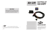
NOTE:
1) REMOVE THREAD PROTECTORS PRIOR TO
VEHICLE INSTALLATION
2) AIR FITTING AND AIR LINE TO BE INSTALLED
WITH THREAD SEALANT AND TORQUED 1-3/4
TURNS BEYOND FINGER TIGHT
3) 5/16 NYLOC NUT TORQUE: 22 Nm (16 ft/lbs)
C or D
B
A
G
F
E
Installation Diagram
TOOLS LIST
Description
Jack Stands
Hoist or Jack
Metric Wrenches
Standard Wrenches
VW Spreader Tool 3424
Center Punch
Hammer
Drill
3/8” Drill Bit
HARDWARE LIST
Item Part # Description................................Qty
A 35243 Strut ....................................................2
B 20997 Leader Hose,1/4” ................................2
C 21810 Union, 1/4” FNPT-1/4” PTC ................2
D 21987 1/4” FNPT X 3/8” Fitting ......................2
E Thread Protector .................................6
F 18433 5/16” Flat Washer ...............................6
G 18438 5/16”-18 Nyloc Nut ..............................6
Missing or damaged parts? Call Air Lift customer
service at (800) 248-0892 for a replacement part.
STOP!
f
ig. 1

5
MN-756
Air Lift Performance
Installing the Air Suspension
PREPARING THE VEHICLE
1. Elevate the vehicle and support the body with a hoist or jack stands.
2. Remove the front wheels.
REMOVING THE STRUT
1. Unbolt the two mounting bolts for the brake caliper and secure or hang the caliper to the
body of the vehicle (g. 2).
DO NOT ALLOW CALIPER TO HANG FROM THE BRAKE LINE OR DAMAGE MAY OCCUR.
2. Unclip the speed sensor wiring from the strut.
3. Remove the three lower bolts from the lower ball joint and control arm. Detach the ball
joint and hub assembly from the control arm (g. 2).
4. To remove the left and right front strut, mark the installed orientation and disconnect the
axle from the transmission drive ange.
TO PREVENT DAMAGE TO THE AXLE JOINT, DO NOT ALLOW THE AXLE TO HANG FREE
5. Remove the bolt at the back of the hub assembly to the strut.
6. Spread the hub assembly slot and push down on the hub to release the strut from its
lower mount. (g. 3 - Volkswagen specic tool is spreader 3424)
CAUTION
CAUTION
f
ig. 2
3424
f
ig. 3

6
MN-756
Air Lift Performance
7. Remove the upper mount nut and remove strut from vehicle.
8. Reattach the lower control arm to the ball joint and torque bolts to 20 Nm (15 ft. lbs.) + 90.
9. Reinstall the axle shaft to the transmission drive ange in the previously installed
orientation. Torque bolts to
M8 x 18: 20 Nm (15 ft. lbs.) + 90°
M8 x 28: 20 Nm (15 ft. lbs.) + 90°
M8 x 48: 20 Nm (15 ft. lbs.) + 90°
M10 x 23: 50 Nm (37 ft. lbs.) + 45°
M10 x 52: 50 Nm (37 ft. lbs.) + 45°
2. Using the supplied template and working from inside the strut pocket, center the template
and orient so that there is clearance for the washers on top. Once the template is centered,
secure in place with tape. Use a center punch and hammer on the center lines of the
template to mark into the drilling surface. Remove the template and drill 3/8” holes through
the strut pocket. Insert the strut upper mounting bracket through the holes. If it does not
t, adjust the holes accordingly. Do not attach the strut to the vehicle body yet.
3. Insert strut into the hub assembly. Reinstall the lower mounting bolt and torque to 70
Nm (52 ft. lbs.) +90°.
4. Lift assembly into strut pocket and align upper mounting bolts with three holes. Using
the supplied nuts and washers, tighten the upper mount to 22 NM (16 lb-ft).
5. Reinstall the brake caliper and torque to 28Nm (21 lb-ft).
6. Attach the speed sensor wiring to the new strut assembly.
INSTALLING THE NEW STRUT ASSEMBLY
1. Install braided hose (B) into the lower end-cap of the airspring with thread sealant or
Teon tape applied to the threads of the tting. Tighten nger tight and torque tting
1-3/4 turns beyond hand tight. Attach the tting (C or D) to the braided line with thread
sealant (g. 4).
f
ig. 4
Before Operating
1. Some vehicles come with a
nine-position damping dial for
added adjustability (g. 5).
If not, proceed to 2.
Before driving your vehicle, set
the new struts to their highest
setting by turning the black dial
on the shaft of the strut as far
as it will go to the right
(position 9).
Increase damping
(stiffer ride)
Decrease damping
(softer ride)
f
ig. 5

7
MN-756
Air Lift Performance
Clearance test — Inate the air springs to 75-90 PSI and make sure there is at least ½”
clearance from anything that might rub against each sleeve. Be sure to check the tire,
brake drum, frame, shock absorbers and brake cables.
Leak test before road test — Inflate the air springs to 75-90 PSI and check all connections
for leaks. All leaks must be eliminated before the vehicle is road tested.
Heat test — Be sure there is sufficient clearance from heat sources, at least 6” for air
springs and air lines. If a heat shield was included in the kit, install it. If there is no heat
shield, but one is required, call Air Lift customer service at (800) 248-0892.
Fastener test — Recheck all bolts for proper torque.
Road test — The vehicle should be road tested after the preceding tests. Inflate the
springs to recommended driving pressures. Drive the vehicle 10 miles and recheck for
clearance, loose fasteners and air leaks.
Operating instructions — If professionally installed, the installer should review the
operating instructions with the owner. Be sure to provide the owner with all of the
paperwork that came with the kit.
INSTALLATION CHECKLIST
Overnight leak down test — Recheck air pressure after the vehicle has been used for
24 hours. If the pressure has dropped more than 5 PSI, then there is a leak that must
be xed. Either x the leak yourself or return to the installer for service.
Air pressure requirements — Regardless of load, the air pressure should always be
adjusted to maintain adequate ride height at all times while driving.
Thirty day or 500 mile test — Recheck the air spring system after 30 days or 500 miles,
whichever comes first. If any part shows signs of rubbing or abrasion, the source should be
identified and moved, if possible. If it is not possible to relocate the cause of the abrasion,
the air spring may need to be remounted. If professionally installed, the installer should
be consulted. Check all fasteners for tightness.
POST-INSTALLATION CHECKLIST
CAUTION
2. Next, completely deate and reinate the air bags 2-3 times. This procedure will purge any
trapped air in the dampers and allow for maximum performance. For ride performance and
the most versatility, Lifestyle recommends setting the strut dial (if equipped) to position
6 or higher.
MAKE SURE THE FRONT WHEELS ARE STRAIGHT WHEN DEFLATING AND
REINFLATING AIR BAGS.
3. Inate and deate the system (do not exceed 125 PSI) to check for clearance or binding
issues. With the air springs deated, check clearances on everything so as not to pinch
brake lines, vent tubes, etc. Clear lines if necessary.
4. Inate the air springs to 75-90 PSI and check all connections for leaks.
5. Air Lift part #27669 or #27671, AutoPilot V2 Air Management System, is highly
recommended for this product.
6. Please continue by reading the Product Use, Maintenance and Servicing section.
Technician’s Signature _________________________________
Date _________________

8
MN-756
Air Lift Performance
MAINTENANCE GUIDELINES
By following these steps, vehicle owners will obtain the longest life and best results from their
air spring.
1. Check the air pressure before driving.
2. Never inate beyond 125 PSI.
3. If you develop an air leak in the system, use a soapy water solution to check all air line
connections, before deating and removing the spring.
4. When increasing load, always adjust the air pressure to maintain normal ride height.
Increase or decrease pressure from the system as necessary to attain normal ride height
for optimal ride and handling. Remember that loads carried behind the axle (including
tongue loads) require more leveling force (pressure) than those carried directly over the
axle.
FOR YOUR SAFETY AND TO PREVENT DAMAGE TO YOUR VEHICLE, DO NOT EXCEED
MAXIMUM GROSS VEHICLE WEIGHT RATING (GVWR), AS INDICATED BY THE VEHICLE
MANUFACTURER. ALTHOUGH YOUR AIR SPRINGS ARE RATED AT A MAXIMUM
INFLATION PRESSURE OF 125 PSI, THE AIR PRESSURE ACTUALLY NEEDED IS
DEPENDENT ON YOUR LOAD.
5. Always add air to the springs in small quantities, checking the pressure frequently. Sleeves
require less air volume than a tire and inate quickly.
6. Should it become necessary to raise the vehicle by the frame, make sure the control system
is turned off before lifting.
1. Leak test the air line connections, threaded connection of the elbow into the air spring, and
the ination valves.
2. Inspect the air lines to be sure none are pinched. Tie straps may be too tight. Loosen or
replace the strap and replace leaking components.
3. Inspect the air line for holes and cracks. Replace as needed.
4. Look for a kink or fold in the air line. Reroute as needed.
If the preceding steps do not solve the problem, it is most likely caused by a failed air spring
— either a factory defect or an operating problem. Please call Air Lift at (800) 248-0892 for
assistance or a replacement air spring.
Q. Will installing air springs increase the weight ratings of a vehicle?
No. Adding air springs will not change the weight ratings (GAWR, GCWR and/or GVWR)
of a vehicle. Exceeding the GVWR is dangerous and voids the Air Lift warranty.
NOTE
CAUTION
Troubleshooting Guide
Product Use, Maintenance and Servicing
Frequently Asked Questions
45 PSI
125 PSI
FAILURE TO MAINTAIN ADEQUATE MINIMUM PRESSURE (OR PRESSURE
PROPORTIONAL TO LOAD) WILL RESULT IN BOTTOMING OUT, OVER-EXTENSION
OR RUBBING AGAINST ANOTHER COMPONENT AND WILL VOID THE WARRANTY.
Maximum Air PressureSuggested Driving Air Pressure

9
MN-756
Air Lift Performance
Q. How long should air springs last?
If the air springs are properly installed and maintained they can last indenitely.
Q. Will raising the vehicle on a hoist for service work damage the air springs?
No. The vehicle can be lifted on a hoist for short-term service work such as tire rotation
or oil changes. However, if the vehicle will be on the hoist for a prolonged period of time,
support the axle with jack stands in order to take the tension off of the air springs.
Pressure determination comes down to three things — level vehicle, ride comfort, and
stability.
1. Level vehicle
If the vehicle’s headlights are shining into the trees or the vehicle is leaning to one side,
then it is not level. Raise the air pressure to correct either of these problems and level
the vehicle.
2. Ride comfort
If the vehicle has a rough or harsh ride it may be due to either too much pressure or not
enough. Try different pressures to determine the best ride comfort. See Air Lift suggested
driving air pressure.
3. Stability
Stability translates into safety and should be the priority, meaning the driver may need
to sacrice a perfectly level and comfortable ride. Stability issues include roll control,
bounce, dive during braking and sponginess. Tuning out these problems usually requires
additional air pressure, strut damping, or both.
1. Inate the air spring to 80 PSI.
2. Spray all connections and the ination valves with a solution of 1/5 liquid dish soap and
4/5 water. Spot leaks easily by looking for bubbles in the soapy water.
3. After the test, deate the springs to the minimum pressure required to restore the system
to normal ride height.
4. Check the air pressure again after 24 hours. A 2-4 PSI loss after initial installation is
normal. Retest for leaks if the loss is more than 5 lbs.
TUNING THE AIR PRESSURE
FIXING LEAKS
CHECKING FOR LEAKS
f
ig. 6
1. If there is a problem with a swivel fitting:
a. Check the air line connection by deating the spring and
removing the line by pulling the collar against the tting
and pulling rmly on the air line. Trim 1” off the end of
the air line. Be sure the cut is clean and square (see g.
6). Reinsert the air line into the push-to-connect tting.
b. Check the threaded connection by tightening the
swivel tting another ½ turn. If it still leaks, deate the
air spring, remove the tting, and re-coat the threads
with thread sealant. Reinstall by hand tightening
as much as possible and then use a wrench for an
additional two turns.
2. If the preceding steps have not resolved the problem, call
Air Lift customer service at (800) 248-0892.

10
MN-756
Air Lift Performance
Air Lift Company warrants its performance products for one year to the original purchaser against manufacturing
defects one year from the date of purchase when used on cars and trucks as specied under normal operating
conditions. The warranty does not apply to products that have been improperly applied, improperly installed, or which
have not been maintained in accordance with installation instructions furnished with all products. The consumer will
be responsible for removing (labor charges) the defective product from the vehicle and returning it, transportation
costs prepaid, to the dealer from which it was purchased or to Air Lift Company for verication.
Air Lift will repair or replace, at its option, defective products or components. A minimum $10.00 shipping and handling
charge will apply to all warranty claims. Before returning any defective product, you must call Air Lift at (800) 248-
0892 in the U.S. and Canada (elsewhere, (517) 322-2144) for a Returned Materials Authorization (RMA) number.
Returns to Air Lift can be sent to: Air Lift Company • 2727 Snow Road • Lansing, MI • 48917.
Product failures resulting from abnormal use or misuse are excluded from this warranty. The loss of use of the product,
loss of time, inconvenience, commercial loss or consequential damages is not covered. The consumer is responsible
for installation/reinstallation (labor charges) of the product. Air Lift Company reserves the right to change the design
of any product without assuming any obligation to modify any product previously manufactured.
This warranty gives you specic legal rights and you may also have other rights that may vary from state-to-state.
Some states do not allow limitations on how long an implied warranty lasts or allow the exclusion or limitation of
incidental or consequential damages. The above limitation or exclusion may not apply to you. There are no warranties,
expressed or implied including any implied warranties of merchantability and tness, which extend beyond this
warranty period. There are no warranties that extend beyond the description on the face hereof. Seller disclaims
the implied warranty of merchantability. (Dated proof of purchase required.)
Warranty and Returns Policy
Contact Information
If you have any questions, comments or need technical assistance contact our customer service
department by calling (800) 248-0892, Monday through Friday. For calls from outside the USA or
Canada, our local number is (517) 322-2144. You may also contact customer service anytime by e-mail at
For inquiries by mail, our address is PO Box 80167, Lansing, MI 48908-0167. Our shipping address for returns is
2727 Snow Road, Lansing, MI 48917.
You may also contact our sales team anytime by e-mail at [email protected] or on the web at
www.airliftperformance.com.
Replacement Information
If you need replacement parts, contact the local dealer or call Air Lift customer service at (800) 248-0892. Most parts
are immediately available and can be shipped the same day.
Contact Air Lift Company customer service at (800) 248-0892 rst if:
• Parts are missing from the kit.
• Need technical assistance on installation or
operation.
• Broken or defective parts in the kit.
• Wrong parts in the kit.
• Have a warranty claim or question.
Contact the retailer where the kit was purchased:
• If it is necessary to return or exchange the kit for any reason.
• If there is a problem with shipping if shipped from the retailer.
• If there is a problem with the price.

11
MN-756
Air Lift Performance
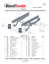
Performance Kit 75518 Template
DASHED LINES ARE FOR WASHER CLEARANCE
NOTE: MAKE SURE THE TEMPLATE IS CORRECT BY
CHECKING HOLE LOCATIONS WITH ACTUAL BRACKET.

Need Help?
Contact our customer service department by calling
(800) 248-0892. For calls from outside the USA or
Canada, our local number is (517) 322-2144.
Air Lift Company • 2727 Snow Road • Lansing, MI 48917 or PO Box 80167 • Lansing, MI 48908-0167
Toll Free (800) 248-0892 • Local (517) 322-2144 • Fax (517) 322-0240 • www.airliftperformance.com
Thank you for purchasing Air Lift Performance products!
Printed in
the USA
/