Page is loading ...

For maximum effectiveness and
safety, please read these instructions
completely before proceeding with
installation.
Failure to read these instructions can result in an
incorrect installation.
MN-963 • (011504) • ERN 8009
INSTALLATION GUIDE
ADJUSTABLE AIR HELPER SPRINGS
TOW AND HAUL WITH SAFETY AND COMFORT
TM
Kit Number
88213


Introduction ............................................. 2
Important Safety Notice ................................................ 2
Notation Explanation ................................................... 2
Installation Diagram ...................................... 3
Hardware List ........................................................4
Tools List ............................................................4
Installing the LoadLifter 5000 Ultimate System ............... 5
Getting Started .......................................................5
Assembling the Air Springs .............................................. 7
Installing the Air Spring Assemblies ....................................... 9
ABS Line Adjustment on Left (Driver) Side ..................................11
Installing the Air Lines ..................................................12
Installing the Heat Shield ................................................14
Checking for Leaks ....................................................15
Fixing Leaks .........................................................15
Photos of Finished Assemblies ...........................................16
Before Operating ........................................17
Installation Checklist ...................................................17
Post-Installation Checklist ...............................................17
Product Use, Maintenance and Servicing ...................18
Minimum and Maximum Pressure .........................................18
Maintenance Guidelines ................................................18
Troubleshooting Guide .................................................18
Frequently Asked Questions .............................................19
Tuning the Air Pressure .................................................19
Guidelines for Adding Air ................................................20
Limited Warranty and Return Policy ........................21
Replacement Part Information .............................21
Contact Information ......................................21
TABLE OF CONTENTS

2
MN-963
LoadLifter 5000 Ultimate
Introduction
The purpose of this publication is to assist with the installation, maintenance and
troubleshooting of the LoadLifter 5000 Ultimate air spring kit. LoadLifter 5000 Ultimate utilizes
sturdy, reinforced, commercial grade single- or double-bellows (depending on the kit). The
bellows are manufactured like a tire with layers of rubber and cords that control growth. An
internal jounce bumper inside the spring absorbs shock and eliminates harsh jarring on rough
roads. The internal jounce bumper replaces the factory bumper and allows the air springs to
safely be run at zero air pressure. LoadLifter 5000 Ultimate kits are recommended for most
3/4 and 1 ton pickups and SUVs with leaf springs, and provide up to 5,000 pounds of load-
leveling support with air adjustability from 5-100 PSI. The kits are also used in motorhome
rear kits and some motorhome fronts where leaf springs are used.
It is important to read and understand the entire installation guide before beginning installation
or performing any maintenance, service or repair. The information here includes a hardware
list, tool list, step-by-step installation information, maintenance tips, safety information and
a troubleshooting guide.
Air Lift Company reserves the right to make changes and improvements to its products and
publications at any time. For the latest version of this manual, contact Air Lift Company at
(800) 248-0892 or visit our website at www.airliftcompany.com.
IMPORTANT SAFETY NOTICE
The installation of this kit does not alter the Gross Vehicle Weight Rating (GVWR) or payload
of the vehicle. Check your vehicle’s owner’s manual and do not exceed the maximum load
listed for your vehicle.
Gross Vehicle Weight Rating: The maximum allowable weight of the fully loaded vehicle
(including passengers and cargo). This number — along with other weight limits, as well
as tire, rim size and ination pressure data — is shown on the vehicle’s Safety Compliance
Certication Label.
Payload: The combined, maximum allowable weight of cargo and passengers that the
vehicle is designed to carry. Payload is GVWR minus the Base Curb Weight.
NOTATION EXPLANATION
Hazard notations appear in various locations in this publication. Information which is
highlighted by one of these notations must be observed to help minimize risk of personal
injury or possible improper installation which may render the vehicle unsafe. Notes are used
to help emphasize areas of procedural importance and provide helpful suggestions. The
following denitions explain the use of these notations as they appear throughout this guide.
INDICATES IMMEDIATE HAZARDS WHICH WILL RESULT IN SEVERE PERSONAL
INJURY OR DEATH.
INDICATES HAZARDS OR UNSAFE PRACTICES WHICH COULD RESULT IN SEVERE
PERSONAL INJURY OR DEATH.
INDICATES HAZARDS OR UNSAFE PRACTICES WHICH COULD RESULT IN DAMAGE
TO THE MACHINE OR MINOR PERSONAL INJURY.
Indicates a procedure, practice or hint which is important to highlight.
DANGER
NOTE
WARNING
CAUTION

3
MN-963
LoadLifter 5000 Ultimate
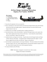
Installation Diagram
g. 1
The P-clamp shown here is
in the right (passenger) side
position on the upper bracket.

4
MN-963
LoadLifter 5000 Ultimate
TOOLS LIST
Description .............................................. Qty
Hoist or oor jacks ................................................ 1
Safety stands ........................................................ 2
Safety glasses ...................................................... 1
Torque wrench...................................................... 1
Standard open-end combo wrenches................... 1
Medium size crescent wrench .............................. 1
Ratchet ................................................................. 1
Metric and standard sockets................................. 1
Description .............................................. Qty
#6 allen wrench (socket if available)..................... 1
7/32” allen wrench (socket if available) ................ 1
5/16” drill bit (very sharp) ...................................... 1
Heavy duty drill ..................................................... 1
Hose cutter, razor blade, or sharp knife ............... 1
Air compressor or compressed air source ............ 1
Spray bottle with dish soap/water solution ........... 1
Item Part # Description................................Qty
A 01531 Clamp bar ...........................................2
B 07954 Frame bracket ..................................... 2
C 07956 Bellows bracket ................................... 2
D 03906 Lower bracket .....................................2
E 58496 Air sring ............................................... 2
F 11967 Roll plate .............................................4
G 21848 90° swivel tting ..................................2
H 17215 3/8”-24 x 7/8” at head screw .............4
I 17203 3/8”-24 x 7/8” hex cap screw...............4
J 18427 3/8” lock washer ..................................4
K 18444 3/8” at washer ..................................12
L 10778 P clamp ...............................................2
Item Part # Description................................Qty
M 17133 3/8”-16 x 6” Carriage Bolt....................4
N 17361 3/8”-16 x 1.25” Carriage Bolt...............4
O 17366 M10-150 X 35 button head screw .......2
P 18435 3/8” nyloc nut ......................................8
AA* 20086 Air line assembly ................................. 1
BB* 10466 Tie strap ..............................................6
CC* 21230 Valve cap ............................................2
DD* 18501 5/16” at washer .................................2
EE* 21234 Rubber washer....................................2
FF* 18401 Star washer ......................................... 2
GG* 21233 5/16” hex nut .......................................4
*Not shown in g. 1.
HARDWARE LIST
Missing or damaged parts? Call Air Lift customer
service at (800) 248-0892 for a replacement part.
STOP!

5
MN-963
LoadLifter 5000 Ultimate
Installing the LoadLifter 5000 Ultimate System
GETTING STARTED
COMPRESSED AIR CAN CAUSE INJURY AND DAMAGE TO THE VEHICLE AND PARTS
IF IT IS NOT HANDLED PROPERLY. FOR YOUR SAFETY, DO NOT TRY TO INFLATE
THE AIR SPRINGS UNTIL THEY HAVE BEEN PROPERLY SECURED TO THE VEHICLE.
1. Raise the vehicle and support it, using jack stands or equivalent, so that the axle can
be safely dropped away from the frame. This will need to be done in order for the air
spring assembly to be positioned between the axle and frame. Figure 2 shows the frame
being supported with the vehicle on a drive-on hoist.
2. Unbolt and remove the stock jounce bumpers from under the frame rails on both sides
(gs. 3 and 4). This is a necessary step to install the kit.
DANGER
g. 2
g. 3
g. 4
Driver side
shown with
jounce
bumper
removed.

6
MN-963
LoadLifter 5000 Ultimate
3. Insert two 3/8-16 X 1.25” carriage bolts (N) through the frame bracket (B). The heads
of the bolts should be on the ange side of the bracket (g. 5).
4. Install the upper frame bracket assembly onto the frame using the M10-150 X 35 button
head screw (O) making sure the ange on the bracket is on the inside of the frame rail
and pointing up (gs. 6 and 7). Push the ange on the bracket up against the frame
and torque screw to 30 ft-lbs.
g. 5
g. 6
g. 7
N
B
Flange
O
Flange
O
Flange
Left (driver)
side shown.
Right
(passenger)
side shown.

7
MN-963
LoadLifter 5000 Ultimate
ASSEMBLING THE AIR SPRINGS
1. Set a roll plate (F) over the top of the bellows (E) (g. 8).
The radius (rounded) edge of the roll plate (F) will be towards the air spring, so that the air
spring is seated inside both roll plates.
2. Install the 90° swivel tting (G) into the top of the bellows, nger-tight plus one and a
half turns.
3. Set the bellows bracket (C) over the bellows and roll plate and attach with the 3/8-24
X 7/8” at head screws (H) (g. 9). Torque to no more than 20 ft-lbs. Repeat for the
other bellows.
NOTE
g. 8
g. 9
F
G
E
C
H

8
MN-963
LoadLifter 5000 Ultimate
4. Insert two 3/8-13 X 6” carriage bolts (M) through the lower bracket (g. 10). Assemble
the lower bracket onto the air spring assembly so the carriage bolts are on the opposite
side of the ttings (g 11). Leave them loose at this time. Attach the lower bracket to the
air spring assembly with two 3/8-24 X 7/8” hex cap screws (I), two 3/8” lock washers
(J) and two 3/8” at washers (K) (g 12). Leave loose at this time.
g. 10
g. 11
g. 12
Attach
the lower
brackets so
the carriage
bolts are
opposite of
the tting on
the air spring
assembly.
I
J
K
M

9
MN-963
LoadLifter 5000 Ultimate
Left side shown:
set one of the
assemblies into
position making
sure that the
carriage bolt
goes in between
the brake/ABS
lines and the axle
as shown.
INSTALLING THE AIR SPRING ASSEMBLIES
1. If not already done, lower the axle enough for clearance to install the assemblies into
position.
2. Set the left (driver) and right (passenger) side assemblies into position making sure
that the long carriage bolt in the rear of the lower bracket, ts between the brake/ABS
lines and the axle (g. 13).
The lower bracket will be nested over the jounce bumper strike plate.
3. Raise the axle or lower the body of the vehicle making sure that the carriage bolts —
previously installed in the frame bracket — nests into the holes of the bellows bracket
(g. 14). On the back carriage bolts only, it will be necessary to install the P clamps (L) on
both sides of the assemblies (the left (driver) and right (passenger)). Cap all the carriage
bolts with 3/8” at washers (K) and a 3/8” nyloc nut (P). Leave them loose at this time.
NOTE
g. 13
g. 14
K
L
P

10
MN-963
LoadLifter 5000 Ultimate
4. Set the axle clamp bar (A) over the long carriage bolts onto the lower bracket, under
the axle and cap with two 3/8” at washers (K) and a 3/8” nyloc nut (P) (g. 15). Leave
loose at this time.
5. The bellows bracket is slotted so that is can be adjusted forward or rearward. Move the
bellows assembly so that the bellows is parallel to the upper and lower bracket. Torque
the upper hardware to 15 ft-lbs.
6. Once the lower bracket (D) is parallel to the upper bracket, the axle clamp bar (A) on
the lower bracket can be torqued evenly to 10 ft-lbs (g. 16).
It may be necessary to pull the brake line away from the carriage bolt slightly on the right
hand side to gain clearance so the line will not rub on the bolt.
7. Once the upper and lower brackets are tight, it will be necessary to tighten the lower
bellows mounting hardware on the lower brackets. Slide the bellows along the slots of
the lower bracket for the nal alignment of the air spring and torque the lower mounting
hardware to no more than 20 ft-lbs (g. 17).
g. 15
g. 16
g. 17
A
K
P
NOTE
A
D
I
J
K

11
MN-963
LoadLifter 5000 Ultimate
ABS LINE ADJUSTMENT ON LEFT (DRIVER) SIDE
1. On the driver side behind the axle, the ABS line will need to be adjusted so that it will
not rub on the lower bracket (g. 18).
2. To do this just pull the line out of the holder on the axle and rotate it 180°, then push it
back into the holder (g. 19). This will change the position of the line so that it will not
come in contact with the lower bracket.
g. 18
g. 19
The ABS
line on the
left (driver)
side will
need to be
moved so
that it does
not rub on
the lower
bracket.
ABS line holder
Dead space between
line and lower bracket

12
MN-963
LoadLifter 5000 Ultimate
INSTALLING THE AIR LINES
1. Choose a convenient location for mounting the ination valves. Popular locations for the
ination valve are:
a. The wheel well anges.
b. License plate recess in bumper.
c. Under the gas cap access door.
d. Through license plate itself.
What ever the chosen location is, make sure there is enough clearance around the ination
valves for an air chuck.
2. Drill a 5/16” hole to install the ination valves.
3. Cut the air line assembly (AA) in two equal lengths.
WHEN CUTTING OR TRIMMING THE AIR LINE, USE A HOSE CUTTER, A RAZOR BLADE
OR A SHARP KNIFE. A CLEAN, SQUARE CUT WILL PREVENT LEAKS. DO NOT USE
WIRE CUTTERS OR SCISSORS TO CUT THE AIR LINE. THESE TOOLS MAY FLATTEN
OR CRIMP THE AIR LINE, CAUSING IT TO LEAK AROUND THE O-RING SEAL INSIDE
THE ELBOW FITTING (FIG. 20).
NOTE
CAUTION
Good Cut Poor Cut
4. Place a 5/16” hex nut (GG) and a star washer (FF) on the air valve. Leave enough of
the ination valve in front of the nut to extend through the hole and have room for the
rubber washer (EE), at washer (DD), and 5/16” hex nut (GG) and valve cap (CC). There
should be enough valve exposed after installation - approximately 1/2” - to easily apply
a pressure gauge or an air chuck (g. 21).
5. Push the ination valve through the hole and use the rubber washer (EE), at washer
(DD), and another 5/16” hex nut (GG). Tighten the nuts to secure the assembly in place
(g. 32).
8. Route the air line along the frame to the air tting on the air spring (g. 22). Keep AT
LEAST 6” of clearance between the air line and heat sources, such as the exhaust pipes,
mufer, or catalytic converter. Avoid sharp bends and edges. Use the plastic tie straps
(BB) to secure the air line to xed, non-moving points along the chassis. Be sure that
the tie straps are tight, but do not pinch the air line. Leave at least 2” of slack to allow
for any movement that might pull on the air line.
g. 20
Air Line to
Bellows
FF
Vehicle body
or bumper
GG
GG
EE
DD
CC
g. 21

13
MN-963
LoadLifter 5000 Ultimate
Option 1
Option 2
g. 22
9. Cut off air line, leaving approximately 12” of extra air line. A clean square cut will ensure
against leaks (see g. 20). Route the hose through the P clamps previously installed, on
both sides. This is especially important for the left (driver) side, to keep the airline away
from the rear HVAC lines if equipped (gs. 23 and 24). Insert the airline into the ttings.
This is a push-to-connect tting. Simply push the air line into the 90° swivel tting until
it bottoms out (9/16” of air line should be in the tting).
g. 23
g. 24
Tie off airline
so as not
to come in
contact with
HVAC lined if
so equipped.

14
MN-963
LoadLifter 5000 Ultimate
INSTALLING THE HEAT SHIELD
Finished photo of heat shield installed on right-side (passenger) exhaust (g. 25).
1. Bend the tabs on the heat shield to provide a 1/2” dead air space between exhaust pipe
and heat shield (g. 26).
2. Attach the heat shield to the exhaust pipe using the clamps (g. 27). Bend the heat shield
for maximum clearance to the air spring.
Bend tabs up
g. 26
At least 1/2” of
dead air space
Distance from
heat shield to
bellows must
be at least 1/2”
1/2”
g. 27
NOTE
g. 25
Forward view
of the axle
showing the
heat shield in
position on
the exhaust.

15
MN-963
LoadLifter 5000 Ultimate
CAUTION
CHECKING FOR LEAKS
1. Inate the air spring to 30 PSI and spray all connections and the ination valves with
a solution of 1/5 liquid dish soap and 4/5 water to check for leaks. Spot leaks easily by
looking for bubbles in the soapy water.
2. After the test, deate the springs to the minimum pressure required to restore the normal
ride height, no less than 5 PSI.
3. Check the air pressure again after 24 hours. A 2-4 PSI loss after initial installation is
normal. Retest for leaks if the loss is more than 5 lbs.
FIXING LEAKS
1. If there is a problem with the swivel tting:
a. Check the air line connection by deating the spring and removing the line by pulling
the collar against the tting and pulling rmly on the air line. Trim 1” off the end of
the air line. Be sure the cut is clean and square (see g. 20). Reinsert the air line
into the push-to-connect tting.
b. Check the threaded connection by tightening the swivel tting another 1/2 turn. If
it still leaks, deate the air spring, remove the tting, and re-coat the threads with
thread sealant. Reinstall by hand tightening as much as possible, then use a wrench
for an additional two turns.
2. If there is a problem with the ination valve, then:
a. Check the valve core by tightening it with a valve core tool.
b. Check the air line connection by removing the air line from the barbed type tting.
DO NOT CUT THE AIR LINE COMPLETELY OFF AS THIS WILL NICK THE BARB AND
RENDER THE FITTING USELESS.
3. If the preceding steps have not resolved the problem, call Air Lift customer service at
(800) 248-0892 for assistance.

16
MN-963
LoadLifter 5000 Ultimate
PHOTOS OF FINISHED ASSEMBLIES
1. Safely remove the jack stands by lowering or raising the vehicle.
2. Figure 28 shows the rear view of the left (driver side) completed installation.
3. Figure 29 shows the rear view of the right (passenger side) completed installation.
g. 28
g. 29

17
MN-963
LoadLifter 5000 Ultimate
Overnight leak down test — Recheck air pressure after the vehicle has been used for
24 hours. If the pressure has dropped more than 5 PSI, then there is a leak that must
be xed. Either x the leak yourself or return to the installer for service.
Air pressure requirements — Regardless of load, the air pressure should always be
adjusted to maintain ride height at all times.
Thirty day or 500 mile test —Recheck the air spring system after 30 days or 500 miles,
whichever comes first. If any part shows signs of rubbing or abrasion, the source should be
identified and moved, if possible. If it is not possible to relocate the cause of the abrasion,
the air spring may need to be remounted. If professionally installed, the installer should
be consulted. Check all fasteners for tightness.
POST-INSTALLATION CHECKLIST
Clearance test — Inflate the air springs to 60 PSI and ensure there is at least 1/2”
clearance around each bellow, away from anything that might rub against them. Be sure
to check the tire, brake drum, frame, shock absorbers and brake cables.
Leak test before road test — Inflate the air springs to 60 PSI, check all connections for
leaks with a soapy water solution. See the Checking for Leaks section for tips on how
to spot leaks. All leaks must be eliminated before the vehicle is road tested.
Heat test — Be sure there is sufficient clearance from any heat sources — at least 6”
for air springs and air lines. If a heat shield was included in the kit, install it. If there is no
heat shield, but one is required, call (800) 248-0892.
Fastener test — Recheck all bolts for proper torque. Retorque after 100 miles.
Road test — The vehicle should be road tested after the preceding tests. Inflate the air
springs to 25 PSI (50 PSI if the vehicle is loaded). Drive the vehicle 10 miles and recheck
for clearance, loose fasteners and air leaks.
Operating instructions — If professionally installed, the installer should review the Product
Use, Maintenance and Servicing section with the owner. Be sure to provide the owner
with all of the paperwork which came with the kit.
Technician’s Signature ________________________
Date ______________
Before Operating
INSTALLATION CHECKLIST (To be completed by installer)

18
MN-963
LoadLifter 5000 Ultimate
Product Use, Maintenance and Servicing
MAINTENANCE GUIDELINES
By following the steps below, vehicle owners will obtain the longest life and best results
from their air springs.
1. Check the air pressure weekly.
2. Always maintain normal ride height. Never inate beyond 100 PSI.
3. If you develop an air leak in the system, use a soapy water solution (1/5 liquid dish
soap and 4/5 water) to check all air line connections and the ination valve core before
deating and removing the air spring.
FOR YOUR SAFETY AND TO PREVENT POSSIBLE DAMAGE TO YOUR VEHICLE, DO
NOT EXCEED MAXIMUM GROSS VEHICLE WEIGHT RATING (GVWR), AS INDICATED
BY THE VEHICLE MANUFACTURER. ALTHOUGH YOUR AIR SPRINGS ARE RATED
AT A MAXIMUM INFLATION PRESSURE OF 100 PSI, THE AIR PRESSURE ACTUALLY
NEEDED IS DEPENDANT ON YOUR LOAD AND GVWR.
4. Loaded vehicles require at least 25 PSI or more. A “loaded vehicle” refers to a vehicle
with a heavy bed load, a trailer, or both. As discussed above, never exceed GVWR,
regardless of air spring, air pressure, or other load assist. The springs in this kit will support
approximately 40 lbs. of load (combined on both springs) for each 1 PSI of pressure.
The required air pressure will vary depending on the state of the original suspension.
Operating the vehicle below the minimum air spring pressure will void the Air Lift warranty.
5. When increasing load, always adjust the air pressure to maintain the normal ride height.
Increase or decrease pressure from the system as necessary to attain normal ride height
for optimal ride and handling. Remember that loads carried behind the axle (including
tongue loads) require more leveling force (pressure) than those carried directly over the axle.
6. Always add air to springs in small quantities, checking the pressure frequently.
7. Should it become necessary to raise the vehicle by the frame, make sure the system is at
minimum pressure (5 PSI) to reduce the tension on the suspension/brake components.
Use of on board leveling systems do not require deation or disconnection.
8. Periodically check the air spring system fasteners for tightness. Also, check the air springs
for any signs of rubbing. Realign if necessary.
9. On occasion, give the air springs a hard spray with a garden hose in order to remove
mud, sand, gravel or other abrasive debris.
TROUBLESHOOTING GUIDE
1. Leak test the air line connections, the threaded connection into the air spring, and all
ttings in the control system.
2. Inspect the air lines to be sure none are pinched. Tie straps may be too tight. Loosen or
replace the strap and replace leaking components.
3. Inspect the air line for holes and cracks. Replace as needed.
4. Look for a kink or fold in the air line. Reroute as needed.
If the preceding steps do not solve the problem, it is possibly caused by a failed air spring — either
a factory defect or an operating problem. Please call Air Lift at (800) 248-0892 for assistance.
NOTE
CAUTION
5 PSI
100 PSI
Maximum Air Pressure
Minimum Recommended Pressure
/