Interface Module PTN-4-CODIR Technical Support
Release 03 05/2020 https://hirschmann-support.belden.eu.com
User Manual
Installation
Dragon PTN
Interface Module PTN-4-CODIR

2 Interface Module PTN-4-CODIR
Release 03 05/2020
The naming of copyrighted trademarks in this manual, even when not specially indicated, should not
be taken to mean that these names may be considered as free in the sense of the trademark and
tradename protection law and hence that they may be freely used by anyone.
© 2020 Hirschmann Automation and Control GmbH
Manuals and software are protected by copyright. All rights reserved. The copying, reproduction,
translation, conversion into any electronic medium or machine scannable form is not permitted,
either in whole or in part. An exception is the preparation of a backup copy of the software for your
own use.
The performance features described here are binding only if they have been expressly agreed when
the contract was made. This document was produced by Hirschmann Automation and Control GmbH
according to the best of the company's knowledge. Hirschmann reserves the right to change the
contents of this document without prior notice. Hirschmann can give no guarantee in respect of the
correctness or accuracy of the information in this document.
Hirschmann can accept no responsibility for damages, resulting from the use of the network
components or the associated operating software. In addition, we refer to the conditions of use
specified in the license contract.
You can get the latest version of this manual on the Internet at the Hirschmann product site
(www.hirschmann.com).
Hirschmann Automation and Control GmbH
Stuttgarter Str. 45-51
72654 Neckartenzlingen
Germany

Interface Module PTN-4-CODIR 3
Release 03 05/2020
Contents
1. INTRODUCTION ......................................................................................................... 5
1.1 General ............................................................................................... 5
1.2 Manual References ............................................................................. 6
2. MODULE DESCRIPTION .............................................................................................. 7
2.1 Front Panel ......................................................................................... 7
2.1.1 Insert/Remove Module into/from Node ................................................... 7
2.1.2 LEDs ............................................................................................................ 8
2.1.3 RJ-45 Ports and Cables ............................................................................... 8
2.2 Functional Operation .......................................................................... 9
2.2.1 General ...................................................................................................... 9
2.2.2 ITU-T G.703 Code Conversion 64kbps ..................................................... 10
2.2.3 CES: SAToP ............................................................................................... 10
2.2.4 CES: CESoPSN ........................................................................................... 11
2.2.5 Hitless Switching ...................................................................................... 11
2.2.6 Single Path ............................................................................................... 12
2.2.7 CODIR - SAToP: Mux/Demux to E1 on 4-E1-L IFM ................................... 13
2.2.8 Delay Comparison in CES (Features) ....................................................... 14
2.2.9 I/O with the Central Switching Module (=CSM) ...................................... 14
2.2.10 Synchronization / Clock Distribution / Network Timing .......................... 14
2.2.11 Test and Loopback Selftests .................................................................... 17
2.3 Onboard Interfaces ........................................................................... 17
2.3.1 Straps ....................................................................................................... 17
2.3.2 DIP Switches ............................................................................................ 17
3. TDM FRAMES/PACKET ............................................................................................. 18
3.1 General ............................................................................................. 18
3.2 Bandwidth ........................................................................................ 18
3.3 Delay ................................................................................................ 18
3.3.1 General .................................................................................................... 18
3.3.2 Delay Parameters .................................................................................... 19
3.3.3 Estimated Delay Calculation and Formulas ............................................. 19
3.3.4 Estimated Delay Examples ....................................................................... 20
3.3.5 Differential Delay ..................................................................................... 20
3.4 Tuning CES = Tuning TDM Frames/Packet .......................................... 21
4. MODULE SPECIFICATIONS ........................................................................................ 21
4.1 General Specifications ....................................................................... 21
4.2 Other Specifications .......................................................................... 21
4.3 Ordering Information ........................................................................ 21
5. ABBREVIATIONS ...................................................................................................... 22

4 Interface Module PTN-4-CODIR
Release 03 05/2020
List of figures
Figure 1 Codirectional Interface .................................................................................................... 5
Figure 2 General 64 kbps Example ................................................................................................ 6
Figure 3 IFM In Aggregation Nodes ............................................................................................... 7
Figure 4 IFM in Core Nodes ........................................................................................................... 7
Figure 5 RJ-45 Connector .............................................................................................................. 8
Figure 6 Detailed Function 64 kbps Example ................................................................................ 9
Figure 7 ITU-T G.703 Code Conversion 64 kbps .......................................................................... 10
Figure 8 General SAToP Example ................................................................................................ 11
Figure 9 General CESoPSN Example ............................................................................................ 11
Figure 10 Hitless Switching .......................................................................................................... 12
Figure 11 Single Path Enabled ..................................................................................................... 13
Figure 12 Single Path Disabled .................................................................................................... 13
Figure 13 CODIR – SAToP: Mux/Demux to E1 on 4-E1-L IFM ...................................................... 14
Figure 14 Clocking: Application D Slaves to Application A via Dragon PTN ................................ 15
Figure 15 Clocking: Both Application A and D Slave to Dragon PTN Clock Master ..................... 15
Figure 16 4-CODIR: Side View ...................................................................................................... 17
Figure 17 Hardware Edition ......................................................................................................... 18
Figure 18 CESoPSN Bandwidth .................................................................................................... 18
Figure 19 Delays .......................................................................................................................... 19
Figure 20 Differential Delay ......................................................................................................... 20
List of Tables
Table 1 Manual References ........................................................................................................... 6
Table 2 LED Indications In Boot Operation ................................................................................... 8
Table 3 LED Indications In Normal Operation ............................................................................... 8
Table 4 RJ-45 Connector: Pin Assignments ................................................................................... 9
Table 5 Difference Between Protection and Hitless Switching ................................................... 12
Table 6 Delay Comparison in CES (Features) ............................................................................... 14
Table 7 Clocking Parameters on Port & Service Level ................................................................. 16
Table 8 Estimated Delay Formulas .............................................................................................. 20
Table 9 Estimated Delay (µs) Examples ....................................................................................... 20
Table 10 Other Specifications ...................................................................................................... 21

Interface Module PTN-4-CODIR 5
Release 03 05/2020
1. INTRODUCTION
1.1 General
This document is valid as of Dragon PTN Release 4.3DR.
The 4-CODIR interface module (=IFM) can transport four 64 kbps links, point-to-point over
the Dragon PTN network according the ITU G.703 standard, see §2.2.2 for more information.
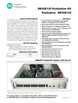
4-CODIR refers to ‘4 ports – Codirectional Interface’. The term 'Codirectional' is used to
describe an interface in which the information and its associated timing signal are
transmitted into the same direction. The information and timing signal are both embedded
in the same data stream, there is no separate clock transmission. The receiver will derive the
clock from the incoming data stream. See figure below.
Figure 1 Codirectional Interface
This IFM converts the incoming data from the 64 kbps link into MPLS-TP packets over the
Dragon PTN network, and vice versa. The destination IFM must also compensate for possible
jitter and network delays to keep everything synchronized. A packetized TDM service is
called a Circuit Emulation Service (=CES). A maximum of 4 CESs can be configured per 4-
CODIR module.
NOTE: A 64kbps link = E0 link; An E1 link can carry 32 E0 links.
Verify the 'Dragon PTN Bandwidth Overview' manual (Ref. [100] in Table 1) to see in which
node and IFM slot this IFM can be used.
The main supported features are:
Packetizing of 64 kbps data
Codirectional
LAN function
Services (See Ref. [2Leg] in Table 1 for the creation of services in HiProvision)
SAToP (=Structured Agnostic TDM over Packet);
CESoPSN (=CES over Packet Switched Network);
Hitless Switching / Single Path;
Mux/Demux (SAToP): Possible to mux/demux this C37.94 service together with other
services to/from one E1 port on a 4-E1-L IFM. Services of different protocol types can
be muxed/demuxed.
A general 64 kbps CODIR example can be found in the next figure:
Equipment Equipment
one signal including
data + timing

6 Interface Module PTN-4-CODIR
Release 03 05/2020
Figure 2 General 64 kbps Example
1.2 Manual References
Table 1 is an overview of the manuals referred to in this manual. ‘&’ refers to the language
code, ‘*’ refers to the manual issue. All these manuals can be found in the HiProvision
(=Dragon PTN Management System) Help function.
Table 1 Manual References
Ref.
Number
Title
[1]
DRA-DRM801-&-*
Dragon PTN Installation and Operation
[2Mgt]
DRA-DRM830-&-*
HiProvision Management Operation
[2Leg]
DRA-DRM832-&-*
Dragon PTN Legacy Services
[2Net]
DRA-DRM833-&-*
Dragon PTN Network Operation
[4]
DRB-DRM803-&-*
Dragon PTN Switching Module: PTN-CSM310-A/ PTN-CSM540-A
[5]
DRE-DRM805-&-*
Dragon PTN Interface Module: PTN-4-E1-L/ PTN-4-T1-L
[6]
DRA-DRM810-&-*
Dragon PTN General Specifications
[7]
DRE-DRM818-&-*
Dragon PTN Interface Module: PTN-16-E1-L/ PTN-16-T1-L
[100]
DRA-DRM828-&-*
Dragon PTN Bandwidth Overview
MPLS-TP Dragon PTN Network
WAN (via SFP on fiber)
64 kbps
Module
4-CODIR
Dragon
PTN Node
Line Protection
Relais
64 kbps
Links
64 kbps
Links
Line Protection
Relais
Packetized 64 kbps via
SAToP or CESoPSN

Interface Module PTN-4-CODIR 7
Release 03 05/2020
2. MODULE DESCRIPTION
2.1 Front Panel
Figure 3 IFM In Aggregation Nodes
Figure 4 IFM in Core Nodes
2.1.1 Insert/Remove Module into/from Node
See ‘Dragon PTN Installation and Operation Manual’ Ref.[1].
LEDs
Port 1, 2, 3, 4:
64 kbps ports
Handle
Spare
LED
Fastening screw
Interface Adapter Kit
Container to insert IFM
Socket Head
Cap Screw
IFM in
Core Node

8 Interface Module PTN-4-CODIR
Release 03 05/2020
2.1.2 LEDs
The meaning of the LEDs depends on the mode of operation (= boot or normal) in which the
4-CODIR module currently is running. After plugging in the module or rebooting it, the
module turns into the boot operation, see Table 2. After the module has gone through all
the cycles in the table below (=rebooted successfully), the module turns into the normal
operation, see LEDs in Table 3.
Table 2 LED Indications In Boot Operation
Cycle
PI
PF
FLT
Spare LED
RX[1..4]
TX[1..4]
1
✓
---
Slow blinking
---
---
---
2
✓
---
Fast blinking
---
---
---
3
✓
---
---
---
---
---
4
✓
---
✓
✓
✓
✓
✓ : LED is lit / --- : LED is not lit
The sub cycle times may vary. The entire boot cycle time [1→ 4] takes approximately 2 minutes.
Table 3 LED Indications In Normal Operation
LED
Color
Status
PI (=Power Input)
Not lit, dark
+12V power input to the board not OK
Green
+12V power input to the board OK
PF (=Power Failure)
Not lit, dark
power generation on the board itself is OK
Red
power generation on the board itself is erroneous
FLT (=FauLT)
Not lit, dark
no other fault or error situation, different from PF, is active on the module
Red
a fault or error situation, different from PF, is active on the module
Spare
Not lit, Green
spare
RX<port n°>
Not lit, dark
No service programmed on port<n>
Green, lit
Service programmed on port<n>, data received on front port<n>
Green, blinking
Service programmed on port<n>, no data received on front port<n>
TX<port n°>
Not lit, dark
No service programmed on port<n>, no TX AIS sent
Green, lit
Service programmed on port<n>, data received on backplane (=network) side
Green, blinking
Service programmed on port<n>, no data received on backplane (=network) side
2.1.3 RJ-45 Ports and Cables
The 4-CODIR module provides four of these ports and each port connector has eight pins.
Each port provides one tip/ring pair. See the figure and table below for an overview and
description. The 120 Ω E1 cable (942 256-201) can be ordered to connect these ports.
Figure 5 RJ-45 Connector
1 8

Interface Module PTN-4-CODIR 9
Release 03 05/2020
Table 4 RJ-45 Connector: Pin Assignments
Pin Number
Description
Cable Wire Colors
1
Rx (Receive) RING
OG
2
Rx (Receive) TIP
WH/OG
3
Not connected
-
4
Tx (Transmit) RING
BU
5
Tx (Transmit) TIP
WH/BU
6, 7, 8
Not connected
-
2.2 Functional Operation
2.2.1 General
An application network (e.g. LAN1) can be connected to the MPLS-TP Dragon PTN network
via one of the 4 front ports. The 4-CODIR module can interface with four 64kbps lines. In
Figure 2, a common functional setup is shown.
In Figure 6 below, a more detailed functional setup is shown. A LAN1 network interfaces the
Dragon PTN node via the front ports on the 4-CODIR module. The 4-CODIR converts this
traffic into Ethernet traffic on the backplane. The Central Switching Module (= CSM, see Ref.
[4] in Table 1) converts this Ethernet traffic into packetized MPLS-TP and transmits it via an
Ethernet IFM (e.g. 4-GC-LW) onto the Dragon PTN MPLS-TP network. The packetizing of 64
kbps occurs via CES: SAToP (see §2.2.3) or CES: CESoPSN (see §2.2.4) technique.
Figure 6 Detailed Function 64 kbps Example
CSM
CSM310-A
IFM1
4-CODIR
IFM2
4-GC-LW
Switch
ETH →
MPLS-TP
Dragon PTN Node
64 kbps
LAN Port
LAN
WAN
4-CODIR
Module
CSM
CSM310-A
IFM1
4-CODIR
IFM2
4-GC-LW
Switch
ETH →
MPLS-TP
Dragon PTN Node
WAN: MPLS-TP (on fiber, copper) →between Dragon PTN nodes
Ethernet →node internal
LAN: 64 kpbs link (on copper) →external devices
Packetized 64 kbps via
SAToP or CESoPSN
MPLS-TP Dragon PTN Network
WAN (via SFP on fiber)
Line Protection
Relais
64 kbps
Links
LAN
Line Protection
Relais
64 kbps
Links

10 Interface Module PTN-4-CODIR
Release 03 05/2020
2.2.2 ITU-T G.703 Code Conversion 64kbps
The ITU-T G.703 standard defines for the 64 Kbps codirectional interface the following five
steps for AMI coding (step1->5) / decoding (step5->1) a binary data stream:
1. (network side) A 64 kbps bit period is divided into four unit intervals;
2. A binary one is coded as a block of the following four bits: 1100;
3. A binary zero is coded as a block of the following four bits: 1010;
4. The binary signal is converted into a three-level signal by alternating the polarity of
consecutive blocks; This is the AMI encoding or Alternate Mark Inversion.
5. (front side) The alternation in polarity of the blocks is violated every eighth block. The
violation block marks the last bit in an octet.
The figure below illustrates these conversion rules. The physical interface consists of four
signals (Transmit, Tip, Transmit Ring, Receive Tip and Receive Ring). A 64 kbps Tip-Ring pair is
a balanced twisted pair (120 Ω). The data transmission through a pair is bipolar and AMI, i.e.
an impulse on the line corresponds to a logical “1” (mark) and a space with a logical “0”.
Figure 7 ITU-T G.703 Code Conversion 64 kbps
2.2.3 CES: SAToP
SAToP is a point-to-point CES which sends transparently an entire E1 frame from the source
to the destination 4-CODIR over the MPLS-TP network. One timeslot is used for transporting
the 64 kbps channel 'X'. The entire frame = all data + synchronization + alignment timeslots =
32 timeslots. One SAToP service can be configured per port.
This way of transportation consumes more bandwidth over the Dragon PTN network than
CESoPSN (see next paragraph), but has less differential delay than CESoPSN. If delay must be
as low as possible, use SAToP instead of CESoPSN to transport your 64 k CESoPSN bps
channel.
NOTE: Each end-point or 64 kbps port must be located in a different node.
7
1
8
0 1
3 4 5
1
6
1
7
1
8
0 10
1
0
2
0
1
Polarity
Violation
Bit Number
64Kbps Data
Steps 1 - 3
Step 4
Step 5
Octet
Timing
Polarity
Violation
data on backplane
data on front ports
DECODING CODING

Interface Module PTN-4-CODIR 11
Release 03 05/2020
Figure 8 General SAToP Example
2.2.4 CES: CESoPSN
CESoPSN is a point-to-point CES which only sends one E1 timeslot including the 64 kbps
channel, over the MPLS-TP Dragon PTN network. This way of transportation consumes less
bandwidth over the Dragon PTN network than SAToP, but has more differential delay than
SAToP. If delay is not an issue, use CESoPSN to transport your 64 kbps channel.
Each end-point or port must be located in a different node.
Figure 9 General CESoPSN Example
2.2.5 Hitless Switching
Hitless Switching is a feature within SAToP/CESoPSN that provides a safe 64 kbps redundant
connection where no data or synchronization is lost when switching from the active to the
backup path or vice versa, e.g. because of cable break. The total delay over the network
remains nearly constant during switch-over. Redundancy via Hitless Switching is obtained via
completing the list below:
creating two independent point-to-point tunnels without protection;
setting the Hitless Switching on at service creation time in HiProvision.
NOTE: See Ref. [2Net]/[2Leg] in Table 1 for the creation of tunnels/services;
On the source side, with Hitless Switching enabled, the E1/T1 IFM duplicates each packet on
a second tunnel (e.g. Tunnel y, see figure below). Each packet also contains a 16 bit
sequence number. Different tunnels mean different paths through the network, with each
path its own delay. Different delays result in a slow and a fast path.
On the destination side, with Hitless Switching enabled, the 4-CODIR IFM buffers the fastest
path and forwards packets from the slowest path on the 64 kbps link. Packets will be
processed according a packet sequence number.
64 kbps port
SAToP
64 kbps channel ‘X’
MPLS-TP Dragon PTN
64 kbps port
64 kbps channel ‘X’‘X’
1 signaling + 30
empty timeslots
1 used
timeslot
Optimal delay
64 kbps port
CESoP
64 kbps channel ‘X’
MPLS-TP Dragon PTN
64 kbps port
64 kbps channel ‘X’‘X’
1 used
timeslot
Optimal bandwidth usage

12 Interface Module PTN-4-CODIR
Release 03 05/2020
Hitless Switching is a redundant mechanism but differs from Protection Switching, see the
table below for an overview. So if redundancy is needed in the service, either choose Hitless
Switching or Protection Switching, mixing up both mechanisms is not allowed. Depending on
the choice, settings must be done at tunnel creation time and/or service creation time.
When Hitless Switching has been enabled, the CES can only start up with two links up,
coming out of a two-links-down situation (except when Single Path has been enabled, see
§2.2.6).
See §2.2.8 for a delay comparison within CES depending on the enabled sub features, see
also further on.
Table 5 Difference Between Protection and Hitless Switching
64 kbps Protection Switching
64 kbps Hitless Switching
required tunnel type
1 point-to-point tunnel
2 point-to-point tunnels
tunnel protection type
1:1;
none; the redundancy is created via two
independent point-to-point tunnels.
service parameter
Hitless Switching = disabled
Hitless Switching = enabled
at switch-over
possible data loss
no data or synchronization loss
total delay
less than hitless switching
more than protection switching
Figure 10 Hitless Switching
2.2.6 Single Path
The Single Path feature is a sub feature of Hitless Switching (see §2.2.5). It influences the
start-up behavior of the Hitless Switching mechanism:
enabled: The CES can already start up with only one link up, coming out of a two-links-
down situation; this setting results in bigger delays because of bigger buffers.
if the fastest path came up first:
the CES starts up according to the fastest path;
possible CES interrupt or minor packet loss when the slowest path comes up
later on;
if the slowest path came up first:
64 kbps
data
64 kbps
data
64 kbps → WAN:
duplicates and transmits
data twice
WAN → 64 kbps:
data buffering = constant delay;
no packet loss at switch-over
MPLS-TP Dragon PTN
Tunnel x has more nodes
= slow path
Tunnel y has less nodes
= fast path

Interface Module PTN-4-CODIR 13
Release 03 05/2020
the CES starts up according to the slowest path;
no CES interrupt or packet loss when the fastest path comes up later on;
See §2.2.8 for a delay comparison within CES depending on the enabled sub features, see
also further on.
Figure 11 Single Path Enabled
Figure 12 Single Path Disabled
2.2.7 CODIR - SAToP: Mux/Demux to E1 on 4-E1-L IFM
When using CODIR SAToP services, it is possibe to mux/demux this 64 kbps CODIR protocol,
together with other same or different protocols to/from port1 on a 4-E1-L IFM. This can be
done via selecting the Mux/Demux option in HiProvision at service creation time.
A maximum of 4 point-to-point SAToP services that support Mux/Demux, regardless the
used protocol, can be muxed to that same E1 port1.
NOTE: All protocols that support Mux/Demux can be found in Ref. [2Leg] in Table 1.
data data
Single Path ENABLED:
ONE link required
no links up:
→ no CES
already with one link up
→ CES starts
64 kbps
MPLS-TP Dragon PTN
MPLS-TP Dragon PTN
64 kbps
data data
Single Path DISABLED:
BOTH links required
only with both links up
→ CES starts
no links up:
→ no CES
64 kbps
MPLS-TP Dragon PTN
MPLS-TP Dragon PTN
64 kbps

14 Interface Module PTN-4-CODIR
Release 03 05/2020
Per extra muxed service to that E1 port1, an extra available E1 port on that 4-E1-L IFM is
required and will be disabled for other service connections. E.g, a second muxed service
disables the next available port (starting with the lowest port number first) on that 4-E1-L
IFM.
The example below shows muxing/demuxing of C37.94, Serial and CODIR 64 kbps to E1. All
ports on the 4-E1-L IFM will be in use in this example because 4 services are
muxed/demuxed, but only port1 will transmit/receive the muxed data stream.
Figure 13 CODIR – SAToP: Mux/Demux to E1 on 4-E1-L IFM
2.2.8 Delay Comparison in CES (Features)
Table 6 Delay Comparison in CES (Features)
CES
Hitless Switching
Single Path
Resulting Delay
✓
---
---
lowest
✓
✓
---
medium
✓
✓
✓
highest
✓ = enabled; --- = disabled
2.2.9 I/O with the Central Switching Module (=CSM)
The 4-CODIR module receives 64 kbps traffic via its front panel ports and converts this into
Ethernet traffic which is forwarded to the CSM via the backplane. The CSM does all the
processing on this data (synchronization, CRC checks, conversions, switching…). The CSM
converts this data into MPLS-TP packets and transmits it an Ethernet IFM (e.g. 4-GC-LW)
onto the WAN. On the destination side, the same processing occurs in reverse order.
2.2.10 Synchronization / Clock Distribution / Network Timing
CAUTION: Make sure to configure/verify the clocking parameters below.
The Dragon PTN network provides a number of mechanisms to perform synchronization /
clock distribution / network timing per CES. The CSM synchronizes all the included IFMs in
the node.
MPLS-TP Dragon PTN
Unused
ALL channels
Site A Site B Site C
Site A
Site B
Site C
SAToP 1 with Mux/Demux
Site A
Site B
Site C
port1 on 4-E1-L IFM
E1 frame
C37.94 frame
Serial Data
CODIR frame
2-C37.94 port
Site D
<protocol x>
Site D
Mux/Demux
on 4-E1-L IFM
Site D
Mux
Demux
7-SERIAL port
SAToP 2 with Mux/Demux
SAToP 3 with Mux/Demux
SAToP 4 with Mux/Demux
4-CODIR port
<x> port
C37.94 Serial CODIR <protocol x>

Interface Module PTN-4-CODIR 15
Release 03 05/2020
The application endpoints in a 'Circuit Emulation: CODIR' service can communicate in a
synchronized way. Which method can be used depends on:
the ‘Clock source’ port setting of the two endpoints;
the 'Differential Clocking' setting in this service;
SyncE availability in the endpoint nodes;
The figures below show relevant end-to-end clocking configurations for this IFM. The PRC
(=Primary Reference Clock) is a very stable high quality clock that can be used as a reference
clock delivered via SyncE to the node:
A, D = Application ports;
B, C = IFM front ports;
Figure 14 Clocking: Application D Slaves to Application A via Dragon PTN
Figure 15 Clocking: Both Application A and D Slave to Dragon PTN Clock Master
Dragon
PTN
A B DC
Internal
Rx
Adaptive
Rx
Dragon
PTN
A B DC
Internal
Rx
Differential
Rx
SyncE, PRC
Clock
Master
Clock
Slave
SyncE, PRC
Dragon
PTN
A B DC
Internal
Rx
Adaptive
Rx
Dragon
PTN
A B DC
Internal
Rx Rx
Clock
Slave
Clock
Slave
Internal
Clock
Master
SyncE, PRC SyncE, PRC

16 Interface Module PTN-4-CODIR
Release 03 05/2020
Table 7 Clocking Parameters on Port & Service Level
Port A:
Clock
Source
Port B:
Clock
Source
Service:
Differential
Clocking
Port C:
Clock
Source
Port D:
Clock
Source
Description
Application D slaves to application A via Dragon PTN
‘Internal
Clock'
‘Rx Clock'
Unchecked
‘Adaptive/
Differential’
‘Rx Clock'
Node (B) recovers the clock from the incoming
data stream from Application (A) and uses it to
decode/encode the packet stream.
Node (C) recovers the clock from the incoming
packet stream from the network and uses it to
encode/decode the data stream. Application (D)
slaves its clock to this stream.
‘Internal
Clock'
‘Rx Clock'
+ SyncE
Checked
‘Adaptive/
Differential’
+ SyncE
‘Rx Clock'
Node (B) recovers the clock from the incoming
data stream from Application (A) and uses it to
decode/encode the packet stream. Node (B)
embeds extra RTP timing information in that
packet stream when forwarding it on the
Dragon PTN network.
Node (C) generates the clock based on the PRC
and the embedded RTP timing information in
the incoming packet stream.
The generated clock is used to encode/decode
the data stream. Application (D) slaves its clock
to this stream.
Both Applications A and D slave to Dragon PTN Clock Master
‘Rx Clock'
‘Internal
Clock’
Unchecked
‘Adaptive/
Differential’
‘Rx Clock'
Node (B) transmits packets to node (C) based on
an Internal Clock. This clock is delivered by the
local oscillator on the IFM. Node (C) recovers
the clock from the incoming packet stream from
the network and uses it to encode/decode data
streams.
Both applications (A) and (D) slave their clock to
the data streams delivered by node (B) and (C).
‘Rx Clock'
‘Internal
Clock’
+ SyncE
Unchecked
‘Internal
Clock’
+ SyncE
‘Rx Clock'
Both nodes (B) and (C) encode/decode the data
stream to/from the end applications based on
the ‘Internal Clock’ on the IFM. This clock is
delivered by the CSM and is based on a PRC
delivered via SyncE to the node.
Both applications (A) and (D) slave their clock to
the data streams delivered by node (B) and (C).
NOTE: SyncE: See the manuals in See Ref. [2Net] and Ref.[4] in Table 1 for more detailed
information;

Interface Module PTN-4-CODIR 17
Release 03 05/2020
2.2.11 Test and Loopback Selftests
Test and Loopback selftests can be performed in CESs, e.g. when configuring or
troubleshooting a CES. Following two functions can be used in a programmed CES:
Loopbacks: on backplane or front port, direction towards line (=application) or network
can be configured;
BERT: test traffic generation and verification via Bit Error Ratio Tester.
CAUTION: enabling selftests disables or disturbs normal service traffic on a port!
For more information and configuration settings, see 'Test and Loopback' in Ref.[1] in
Table 1.
2.3 Onboard Interfaces
Figure 16 4-CODIR: Side View
2.3.1 Straps
No user relevant straps.
2.3.2 DIP Switches
a. Hardware Edition
The Hardware Edition (Figure 16) is set in decimal code using rotary switches S2 to S3 (=most
significant). It can be read out as well via HiProvision. This edition has been factory set and
MUST NOT BE CHANGED! Example: Setting S3=’0’ and S2=’5’ indicates Hardware Edition ‘5’
(dec).
Hardware
Edition

18 Interface Module PTN-4-CODIR
Release 03 05/2020
Figure 17 Hardware Edition
3. TDM FRAMES/PACKET
3.1 General
In a CES service, the amount of TDM Frames per Ethernet packet is an important setting
because it influences the amount of consumed bandwidth and delay through the network.
The more TDM Frames/Packet, the less bandwidth is used but the bigger the total delay
through the network.
In HiProvision, it can be configured how many TDM Frames/Packet can be encoded.
Default TDM Frames/Packet = 4;
Maximum TDM Frames/Packet, no Hitless Switching: 24;
Maximum TDM Frames/Packet, Hitless Switching: 10.
3.2 Bandwidth
If only one TDM frame per packet is encoded, it generates a lot of header information on the
network resulting in a lot of consumed bandwidth. Encoding more frames into one packet
will decrease the amount of header information and as a result the consumed bandwidth as
well. As of 8 frames per packet and higher, the bandwidth consumption stabilizes towards
the minimum bandwidth consumption. See the graph below.
Figure 18 CESoPSN Bandwidth
3.3 Delay
3.3.1 General
The total delay between two end points over the Dragon PTN network depends on:
P (=Packetization Delay): Delay to encode 64 kbps input into MPLS-TP packets;

Interface Module PTN-4-CODIR 19
Release 03 05/2020
Path Delay: Delay from source to destination over the MPLS-TP network path; can be
measured by HiProvision via OAM delay measurement for the specific service; Path
Delay = Delay external network (if any) + 5µs/km + 10µs/node;
DP (=Depacketization Delay): Delay to decode MPLS-TP packets into 64 kbps output;
DPh: Extra Depacketizing Delay due to hitless switching;
Total Delay = Total Network delay between two 64 kbps applications;
Total Delay = (Packetization + Path + Depacketization + Hitless Switching) Delay;
Figure 19 Delays
3.3.2 Delay Parameters
These delays in §3.3.1 depend on the selected service in HiProvision and its configured delay
parameters. HiProvision offers the delay parameters listed below to tune the delay.
CAUTION: If you are not familiar with these parameters, keep the default values.
TDM Frames per Packet: The lower the value, the lower the delay.
Jitter Buffer Size (µs): advice: Set this value to ‘Packetizing Delay + expected peak-to-
peak jitter (µs)’; The default peak-to-peak jitter could be 250 µs; The expected peak-to-
peak jitter (µs) must be measured in the network. If the packetizing delay ‘P’ <2000 µs,
set the buffer size to at least 2000 µs. If the packetizing delay ‘P’ > 2000 µs (e.g. 2500 µs),
set the buffer size to at least e.g. 2500 µs.
CAUTION: By default, the jitter buffer will reset once for optimal processing 15 sec-
onds after a change in the service occurs. This reset will cause a minimal loss of da-
ta. See ‘jitter buffer’ in the Ref. [2Leg] in Table 1 for more information.
Maximum Network Path Delay Difference (µs) (only for Hitless Switching): advise: Set
this value to ‘(Two Paths nodes difference)*10 + expected peak-to-peak jitter(µs)’. If
path1 has 17 nodes and path2 has 8 nodes, this is a difference of 9 nodes. You could set
MaxNetwPathDelayDiff = 9*10 + 250 = 340 µs;
3.3.3 Estimated Delay Calculation and Formulas
Table 8 shows formulas to calculate an estimated delay. Once you have the desired
estimated delay, fill out the parameter values in HiProvision, which shows the calculated
‘P+DP+DPh’.
64 kbps
APPLICATION
MPLS-TP Dragon PTN
64 kpbs
APPLICATION
Total Delay
Path Delay
(De)Packetization Delay
+ Hitless Switching Delay
(De)Packetization Delay
+ Hitless Switching Delay

20 Interface Module PTN-4-CODIR
Release 03 05/2020
Table 8 Estimated Delay Formulas
Delay
No Hitless Switching
Hitless Switching
P
TDMFramesPerPacket * 125
Path Delay
measured by HiProvision
DP
(JitterBufferSize – P) / 2
DPh
0
2P + MaxNetwPathDelayDiff + 1087
Total
P + Path Delay + DP + DPh
3.3.4 Estimated Delay Examples
Find some example values below. Fill them out in the formulas to find the estimated total
delay:
TDMFramesPerPacket = 10
Pathdelay (measured by HiProvision) = 500 µs
JitterBufferSize = 4000 µs
MaxNetwPathDelayDiff = 340 µs
Table 9 Estimated Delay (µs) Examples
Delay
No Hitless Switching
Hitless Switching
P
10 * 125 = 1250
Path Delay
500
DP
(4000 – 1250) / 2 = 1375
DPh
0
2*1250 + 340 + 1087 = 3927
Total
1250 + 500 + 1375 + 0 = 3125 µs
1250 + 500 + 1375 + 3927 = 7052 µs
3.3.5 Differential Delay
Differential Delay is the difference in Path Delays between two end-points, measured in two
opposite directions over the same path.
Figure 20 Differential Delay
64 kbps
APPLICATION
MPLS-TP Dragon PTN
64 kbps
APPLICATION
Differential Delay = Difference (Path Delay 1;Path Delay2)
Path Delay1
Path Delay2
Page is loading ...
Page is loading ...
/