Altronix TANGO8AP Installation guide

Type
Installation guide

Altronix TANGO8AP converts PoE input into regulated 12/24VDC outputs and protected 12/24VDC outputs, eliminating the need for high voltage inside an enclosure. It supports a single 12V LiFePO4 battery for 12/24VDC backup, has eight trigger inputs, eight selectable outputs, a Form "C" relay, and selectable fire alarm disconnect for each output. Ideal for access control, it provides 30 minutes of backup with a 4Ah battery, 45 minutes with a 7Ah battery, and 1.5 hours with a 12Ah battery.

Altronix TANGO8AP converts PoE input into regulated 12/24VDC outputs and protected 12/24VDC outputs, eliminating the need for high voltage inside an enclosure. It supports a single 12V LiFePO4 battery for 12/24VDC backup, has eight trigger inputs, eight selectable outputs, a Form "C" relay, and selectable fire alarm disconnect for each output. Ideal for access control, it provides 30 minutes of backup with a 4Ah battery, 45 minutes with a 7Ah battery, and 1.5 hours with a 12Ah battery.

Rev. TANGO8AP-083019 More than just power.TM
Installing Company: _______________ Service Rep. Name: __________________________________
Address: _____________________________________________ Phone #: __________________
Tango8AP Series
PoE Driven Multi-Output
Power Supply/Charger
With Access Power Controller
Models Include:
Tango8AP
- 12VDC and/or 24VDC selectable by output @ 65W max.
- Eight (8) selectable Fail Safe, Fail-Secure fused outputs or Form “C” dry outputs
- Fire Alarm Disconnect selectable by output
- Eight (8) additional fused outputs
- Built-in Lithium Iron Phosphate Battery Charger
Tango8APCB
- 12VDC and/or 24VDC selectable by output @ 65W max.
- Eight (8) selectable Fail Safe, Fail-Secure PTC outputs or Form “C” dry outputs
- Fire Alarm Disconnect selectable by output
- Eight (8) additional PTC outputs
- Built-in Lithium Iron Phosphate Battery Charger
Installation Guide
- 2 - Tango8AP(CB) - PoE Driven Multi-Output Power Supply/Charge With Access Power Controller Installation Guide
Table of Contents:
Overview .................................................................pg. 3
Specifications .............................................................pg. 3
Stand-by Specifications .....................................................pg. 4
Installation Instructions ......................................................pg. 5
Wiring ...................................................................pg. 7
LED Diagnostics. . . . . . . . . . . . . . . . . . . . . . . . . . . . . . . . . . . . . . . . . . . . . . . . . . . . . . . . . . . . pg. 7
Terminal Identification ......................................................pg. 8
Typical Application Diagram for ACMS8(CB) .....................................pg. 10
ACMS8(CB) Hook-Up Diagrams ................................................pg. 11
Enclosure Dimensions .......................................................pg. 12
Tango8AP(CB) - PoE Driven Multi-Output Power Supply/Charge With Access Power Controller Installation Guide - 3 -
Overview:
Altronix Tango8AP(CB) PoE Driven Multi-Output Power Supply/Charger With Access Power Controller converts an
IEEE802.3bt PoE input into eight (8) regulated 24VDC and/or 12VDC outputs and eight (8) protected 24VDC and/
or 12VDC outputs up to 65W. It eliminates the need for a high voltage inside of an enclosure. Tango8AP(CB) is
designed to support a single 12VDC LiFePO4 (Lithium Iron Phosphate) battery for 12VDC and 24VDC backup.
Specifications:
Inputs:
Tango1B:
• 802.3bt PoE up to 90W or 802.3at up to 30W or 802.3af up to 15W.
ACMS8/ACMS8CB:
Eight (8) trigger inputs:
a) Normally open (NO) inputs (dry contacts).
b) Normally closed (NC) inputs (dry contacts).
c) Open collector sink inputs.
d) Wet Input (5VDC - 24VDC) with 10K resistor
e) Any combination of the above.
Outputs:
Tango1B:
• 12VDC up to 5.4A (65W) and/or 24VDC up to 2.7A (65W). Combined output not to exceed 65W.
When charging batteries:
12VDC up to 4.6A (55W) and/or 24VDC up to 2.3A (55W). Combined output not to exceed 55W.
• ACMS8:
- Fuse protected outputs rated @ 2.5A per output, non power-limited. Total output 20A max.
ACMS8CB:
- PTC protected outputs rated @ 2A per output, Class 2 power-limited. Total output 16A max.
Do not exceed the individual power supply ratings. See Input/Output Voltage Ratings, pg. 6.
Total output current should not exceed max. current rating of the power supplies employed on each input.
See Maximum Output of Altronix Power Supplies.
Eight (8) selectable independently controlled outputs or eight (8) indepently controlled Form “C” relay outputs
(see below for ratings):
a) Fail-Safe and/or Fail-Secure power outputs.
b) Form “C” relays rated @ 2.5A. 5, 12, 24VDC, 0.6 Power Factor (ACMS8 only).
c) Auxiliary power outputs (unswitched).
d) Any combination of the above.
Individual outputs may be set to OFF position for servicing (output jumper set to middle position).
Does not apply to Dry Contact applications.
Any of the eight (8) fuse/PTC protected power outputs are selectable to follow power Input 1 or Input 2.
Output voltage of each output is the same as the input voltage of the input selected.
See Input/Output Voltage Ratings, pg. 6.
PDS8:
Fuse protected outputs rated @ 3A per output, non power-limited.
PDS8CB:
PTC protected outputs rated @ 2A per output, Class 2 power-limited.
Surge suppression.
Fuse/PTC Ratings:
ACMS8(CB)
- Main input fuses rated 15A/32V each.
- ACMS8: output fuses are rated 3A/32V.
- ACMS8CB: Output PTCs are rated 2A.
• PDS8(CB):
- Main input fuses rated @ 10A/32V each.
- PDS8: output fuses rated @ 3A/32V each.
- PDS8CB: output PTCs rated @ 2A each.
TANGO1B: battery fuse rated @ 10A/32V each.
- 4 - Tango8AP(CB) - PoE Driven Multi-Output Power Supply/Charge With Access Power Controller Installation Guide
Specifications (cont’d):
Ethernet Output (Tango1B):
• Pass-through Ethernet Port (data only).
• 100/1G.
Battery (Tango1B):
• 12VDC battery charger for Lithium Iron Phosphate Battery (LiFeP04 only).
• Unique technology allows for single battery to backup 12VDC and/or 24VDC systems.
• Low power shutdown. Shuts down DC output terminals if battery voltage drops below 80% of nominal.
Prevents deep battery discharge.
Supervision (Tango1B):
• Loss of PoE Input.
• Battery Supervision.
Fire Alarm Disconnect:
• Fire Alarm disconnect (latching or non-latching) is individually selectable for any or all of the eight (8) outputs.
Fire Alarm disconnect input options:
a) Normally open [NO] or normally closed [NC] dry contact input.
Polarity reversal input from FACP signaling circuit.
FACP input WET is rated 5-30VDC 7mA.
FACP input EOL requires 10K end of line resistor.
FACP output relay [NC]: either Dry 1A/28VDC, 0.6 Power Factor or 10K resistance with [EOL JMP] intact.
Visual Indicators:
Tango1B
- Input indicates input voltage is present.
- Battery status indicates battery trouble condition.
- PoE Class indicator.
- Supervision PoE Fail or BAT Fail.
ACMS8(CB)
- Red LEDs indicate outputs are triggered.
- Blue LED indicates FACP disconnect is triggered.
- Individual voltage LED indicates 12VDC (Green) or 24VDC (Red).
PDS8(CB)
- Individual voltage LEDs indicate 12VDC (Green) or 24VDC (Green and Red).
Environmental:
• Operating temperature: 0ºC to 49ºC ambient.
• Humidity: 20 to 85%, non-condensing.
Enclosure Dimensions (approximate H x W x D):
15.5” x 12.25” x 4.5” (394mm x 311mm x 114mm).
Accessories:
Power Sourcing Equipment
NetWay1BT - Single Port Managed Hi-PoE Injector supplies 90W total power.
NetWaySP1BT - 802.3bt Media Converter/Injector supplies 90W total power.
NetWay4BT - 4-Port Managed Hi-PoE Midspan Injector supplies 480W total power.
NetWay8BT - 8-Port Managed Hi-PoE Midspan Injector supplies 480W total power.
Stand-by Specifications:
Battery Access Control Applications Stand-by
4AH 30 Mins.
7AH 45 Mins.
12AH 1.5 Hours
Tango8AP(CB) - PoE Driven Multi-Output Power Supply/Charge With Access Power Controller Installation Guide - 5 -
Installation Instructions:
Wiring methods shall be in accordance with the National Electrical Code/NFPA 70/NFPA 72/ANSI, the Canadian
Electrical Code and with all local codes and authorities having jurisdiction. Product is intended for indoor use only.
1. Mount unit in desired location. Mark and predrill holes in the wall to line up with the top two keyholes in
the enclosure. Install two upper fasteners and screws in the wall with the screw heads protruding. Place the
enclosure’s upper keyholes over the two upper screws, level and secure. Mark the position of the lower two
holes. Remove the enclosure. Drill the lower holes and install the two fasteners. Place the enclosure’s upper
keyholes over the two upper screws. Install the two lower screws and make sure to tighten all screws
(Enclosure Dimensions, pg. 12). Secure enclosure to earth ground.
Tango1B:
2. Connect IEEE802.3bt PSE from PoE source to RJ45 Jack marked [PoE+ Data Input] on the Tango1B board
(Fig. 1b, pg. 5). If Data pass-through is required, connect another IEEE802.3bt PSE to RJ45 Jack marked
[Data Output] (Fig. 1a, pg. 5).
CAUTION: Do not touch exposed metal parts.
There are no user serviceable parts inside. Refer installation and servicing to qualified service personnel.
3. When the use of stand-by batteries is desired, they must be Lithium Iron Phosphate (LiFePO4).
Connect batteries to the terminals marked [+ BAT –] on Tango1B (battery leads included) (Fig. 1f, pg. 5).
4. Connect appropriate signaling notification devices to terminals marked [C FAIL NC] (Fig. 1c, pg. 5)
supervisory relay output.
Fig. 1 - Tango1B with PDS8 Stacked Above
1a
1b
1c
1d
1e
1f
PDS8
PDS8CB
Dual Voltage
Power Distribution
Module
+ INP1 --
PWR1 +
OFF
IN1
IN2
Out1
<1 off 2>
PWR1 +
PWR2 +
PWR2 +
COM (--- )
COM (--- )
+ INP2 --
IN2 Fuse
IN1 Fuse
Common Power Outputs (NEG)
N
P
OUT1 OUT2 OUT3 OUT4 OUT5 OUT6 OUT7 OUT8
1 2 3 4 5 6 7 8
10
10
3
3
333333
Out2
<1 off 2>
Out3
<1 off 2>
Out4
<1 off 2>
Out5
<1 off 2>
Out6
<1 off 2>
Out7
<1 off 2>
Out8
<1 off 2>
1g
PDS8(CB):
1. Ensure all output jumpers [OUT1 - OUT8] on PDS8(CB) are placed in the
OFF (center) position marked [•] (Fig. 2, pg. 5).
2. Set each output [OUT1 - OUT8] to route power from Input 1 or Input 2
(jumper position 1 or 2) (Fig. 1, 2, pg. 5, Fig. 3 pg. 6). IN1 = 24VDC, IN2 = 12VDC.
Note: Measure output voltage before connecting devices.
This helps avoiding potential damage.
3. Connect devices to terminal pairs 1 to 8, marked [P (Positive) - OUT1-OUT8, N (Negative)]
(Fig. 1, pg. 5, Fig. 3 pg. 6).
ACMS8(CB):
1. Ensure all output jumpers [PWR1] - [PWR8] are placed in the
OFF (center) position (Fig. 3, pg. 5).
2. Set each output [OUT1] - [OUT8] to route power from Input 1 or 2 (Fig. 3, pg. 5).
Note: Measure output voltage before connecting devices.
This helps avoiding potential damage.
3. Turn power off before connecting devices.
OFF
IN1
IN2
Fig. 2
PWR1
PWR2
OFF
Fig. 3
- 6 - Tango8AP(CB) - PoE Driven Multi-Output Power Supply/Charge With Access Power Controller Installation Guide
4. Output Options:
ACMS8(CB) will provide up to eight (8) switched power outputs or eight (8) dry form “C” outputs, or any
combination of both switched power and form “C” outputs, plus eight (8) unswitched auxiliary power outputs.
Switched Power outputs:
Connect the negative (–) input of the device being powered to the terminal marked [COM].
For Fail-Safe operation connect the positive (+) input of the device being powered to the terminal
marked [NC].
For Fail-Secure operation connect the positive (+) input of the device being powered to the terminal
marked [NO].
Form “C” outputs:
When form “C” outputs are desired, the corresponding jumper (1-8) must be placed in the OFF position
(Fig. 3, pg. 5). Alternatively, the corresponding output fuse (1-8) can be removed (Tango8AP only).
Connect negative (–) of the power supply directly to the locking device.
Connect the positive (+) of the power supply to the terminal marked [C].
For Fail-Safe operation connect the positive (+) of the device being powered to the terminal marked [NC].
For Fail-Secure operation connect the positive (+) of the device being powered to the terminal marked [NO].
Dry contacts rated @ 2.5A, 28VDC.
Auxiliary Power outputs (unswitched):
Connect positive (+) input of the device being powered to the terminal marked [C] and the negative (–)
of the device being powered to the terminal marked [COM]. Output can be used to provide power for
card readers, keypads etc.
5. Turn main power on after all devices are connected.
6. Input Trigger options:
Note: If Fire Alarm disconnect is not used, connect a 10K ohm resistor to terminals marked [GND and EOL],
plus connect a jumper to terminals marked [GND, RST].
Normally Open (NO) Input:
Slide input control logic DIP switch into the OFF position for [Switch 1-8]
(Fig. 4, on right). Connect your wires to terminals marked [+ INP1 –] to [+ INP8 –].
Normally Closed (NC) Input:
Slide input control logic DIP switch into the ON position for [Switch 1-8]
(Fig. 4, on right). Connect your wires to terminals marked [+ INP1 –] to [+ INP8 –].
Open Collector Sink Input:
Connect the open collector sink input to the terminal marked [+ INP1 –] to [+ INP8 –].
Wet (Voltage) Input Configuration:
Carefully observing polarity, connect the voltage input trigger wires and the supplied 10K resistor to
terminals marked [+ INP1 –] to [+ INP8 –].
If applying voltage to trigger input - set the corresponding INP Logic switch to the “OFF” position
If removing voltage to trigger input - set the corresponding INP Logic switch to the “ON” position.
7. Fire Alarm Interface options (See page 11):
A normally closed [NC], normally open [NO] input or polarity reversal input from
FACP signaling circuit will trigger selected outputs. To enable FACP Disconnect
for an output turn the corresponding DIP switch [SW1-SW8] ON.
To disable FACP disconnect for an output turn the corresponding DIP switch [SW1-SW8]
OFF. Switch is located directly to the left of the Fire Alarm Interface Terminals.
Normally Open Input:
Wire your FACP relay and 10K resistor in parallel on terminals marked [GND] and [EOL].
Normally Closed Input:
Wire your FACP relay and 10K resistor in series on terminals marked [GND] and [EOL].
FACP Signaling Circuit Input Trigger:
Connect the positive (+) and negative (–) from the FACP signaling circuit output to the terminals marked
[+ FACP –]. Connect the FACP EOL to the terminals marked [+ RET –] (polarity is referenced in an
alarm condition).
Non-Latching Fire Alarm Disconnect:
Connect a jumper to the terminals marked [GND, RST].
Latching Fire Alarm Disconnect:
Connect a NO normally open reset switch to terminals marked [GND, RST].
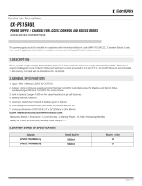
1
2
3
4
INP Logic
NC <-> NO
ON
Fig. 4
Fig. 5
FACP
EN <-- > DIS
1
2
3
4
ON
Tango8AP(CB) - PoE Driven Multi-Output Power Supply/Charge With Access Power Controller Installation Guide - 7 -
8. FACP Dry NC output:
Connect desired device to be triggered by the unit’s dry contact output to the terminals marked [NC] and [C].
When [EOL JMP] is kept intact, the output is of 0 Ohm resistance in a normal condition.
When [EOL JMP] is clipped, a 10k resistance will be passed to next device when in a normal condition.
PWR1 +
PWR2 +
COM -
COM -
PWR2 +
PWR1 +
+ PWR2 --
+ PWR1 --
INP Logic
NO <--> NC
FACP
EN <--> DIS FACP
FACP
FACP
Power 2
Power 1
+INP2--+INP1-- +INP3-- +INP4-- +INP5-- +INP6-- +INP7-- +INP8--
1
2
3
4
5
6
7
8
1
2
3
4
5
6
7
8
ONON
NC RST EOL +F +R
C GND GND -F -R
NO C NC COM NO C NC COM
Output 1 Output 2
NO C NC COM NO C NC COM
Output 3 Output 4
NO C NC COM NO C NC COM
Output 5 Output 6
NO C NC COM NO C NC COM
Output 7 Output 8
Wiring:
Use 18 AWG or larger for all low voltage power connections.
LED Diagnostics:
Tango1B
LED ON BLINKING
Input Input voltage is present. Input voltage not present.
Battery Normal operating condition. Battery is low or missing.
PoE Indicates Class. Refer to table below Classes 3-8
Supervision PoE Fail or BAT Fail. NC dry contact 30V 1A (not an LED)
Class Green Red Blue Class Green Red Blue
Class 1 Class 5 On Off On
Class 2 Class 6 On Off On
Class 3 Off Off Off Class 7 On On On
Class 4 Off On Off Class 8 On On On
PDS8:
LED ON
Green 12VDC Output.
Green and Red 24VDC Output.
ACMS8 and ACMS8CB Access Power Controller
LED ON OFF
LED 1- LED 8 (Red) Output relay(s) de-energized. Output relay(s) energized.
FACP FACP input triggered (alarm condition). FACP normal (non-alarm condition).
Green Output 1-8 12VDC –
Red Output 1-8 24VDC –
Fig. 6 - ACMS8
- 8 - Tango8AP(CB) - PoE Driven Multi-Output Power Supply/Charge With Access Power Controller Installation Guide
Terminal Identification:
Tango1B
Terminal/RJ45 Legend Function/Description
PoE+ Data Input IEEE802.3bt Input (Fig. 1b, pg. 5).
Data Output Passes Data to Switch (Fig. 1a, pg. 5)
C FAIL NC Power and Battery Fail (Fig. 1c, pg. 5).
+ 12V – 12VDC output (Fig. 1d, pg. 5).
+ 24V – 24VDC output (Fig. 1e, pg. 5).
+ BAT – Lithium Iron Phosphate battery backup (Fig. 1f, pg. 5).
8-Pin Connector (Fig. 2g, pg. 4) Facilitates electrical connection to PDS8(CB).
PDS8(CB):
Terminal Legend Function/Description
+ INP1 – Factory connected to Tango1B. Do not use these terminals.
+ INP2 – Factory connected to Tango1B. Do not use these terminals.
P [OUT1-OUT8] Positive DC power outputs.
N [OUT1-OUT8] Negative DC power outputs.
ACMS8 and ACMS8CB Access Power Controller
Terminal Legend Function/Description
+ PWR1 Factory connected. Do not use these terminals.
+ PWR2 Factory connected. Do not use these terminals.
+ INP1 – through
+ INP8 –
Eight (8) independently controlled Normally Open (NO), Normally Closed (NC),
Open Collector Sink or Wet Input Triggers.
C, NC FACP Dry NC output rated 1A/28VDC @ 0.6 Power Factor. Class 2 power-limited.
With EOL JMP intact, will provide 10k resistance in a normal state.
GND, RST FACP interface latching or non-latching. NO dry input. Class 2 power-limited.
To be shorted for non-latching FACP interface or Latch FACP reset.
GND, EOL EOL Supervised FACP Input terminals for polarity reversal FACP function.
Class 2 power-limited.
F, + F, – R, + R FACP Signaling Circuit Input and Return terminals. Class 2 power-limited.
Output 1 through Output 8
NO, C, NC, COM
Eight (8) selectable independently controlled outputs [Fail-Safe (NC) or Fail-Secure
(NO)] and eight (8) independently controlled Form “C” Relay outputs.
Tango8AP(CB) - PoE Driven Multi-Output Power Supply/Charge With Access Power Controller Installation Guide - 9 -
Fig. 7 - Tango8AP(CB)
PDS8
PDS8CB
Dual Voltage
Power Distribution
Module
+ INP1 --
PWR1 +
OFF
IN1
IN2
Out1
<1 off 2>
PWR1 +
PWR2 +
PWR2 +
COM (--- )
COM (--- )
+ INP2 --
IN2 Fuse
IN1 Fuse
Common Power Outputs (NEG)
N
P
OUT1 OUT2 OUT3 OUT4 OUT5 OUT6 OUT7 OUT8
1 2 3 4 5 6 7 8
10
10
3
3
333333
Out2
<1 off 2>
Out3
<1 off 2>
Out4
<1 off 2>
Out5
<1 off 2>
Out6
<1 off 2>
Out7
<1 off 2>
Out8
<1 off 2>
Supervision
(power-limited)
PoE Input
Data Pass-Through
LiFeP04 Battery
connection
(non power-limited)
DC Output to devices
(Tango8AP - non power-limited, Tango8APCB - power-limited)
PTC
Protected
Outputs on
Tango8APCB
PWR1 +
PWR2 +
COM -
COM -
PWR2 +
PWR1 +
+ PWR2 --
+ PWR1 --
INP Logic
NO <--> NC
FACP
EN <--> DIS FACP
FACP
FACP
Power 2
Power 1
+INP2--+INP1--+INP3-- +INP4-- +INP5-- +INP6-- +INP7-- +INP8--
1
2
3
4
5
6
7
8
1
2
3
4
5
6
7
8
ONON
NC RST EOL +F +R
C GND GND -F -R
NO C NC COM NO C NC COM
Output 1Output 2
NO C NC COM NO C NC COM
Output 3Output 4
NO C NC COM NO C NC COM
Output 5 Output 6
NO C NC COM NO C NC COM
Output 7 Output 8
Supervision and
FACP Interface
(power-limited)
ACMS8(CB) and PDS8(CB)
are factory connected Independently controlled Input Triggers
DC Output to devices
(Tango8AP - non power-limited, Tango8APCB - power-limited)
Optional
LiFeP04
Battery
- 10 - Tango8AP(CB) - PoE Driven Multi-Output Power Supply/Charge With Access Power Controller Installation Guide
Typical Application Diagram for ACMS8(CB):
Fig. 8
OUT1
RISK OF FIRE REPLACE FUSES WITH SAME TYPE AND RATING
OUT2
OUT3
OUT4
OUT5
OUT6
OUT7
OUT8
PWR1+
PWR1
PWR1<-- > PWR2
PWR1<-- > PWR2
PWR1<-- > PWR2
PWR1<-- > PWR2
PWR1<-- > PWR2
INP Logic
NC <-- > NO
FACP
EN <-- > DIS
FACP
PWR2+
Power 2
Power 1
+INP2--+INP1-- +INP3-- +INP4-- +INP5-- +INP6-- +INP7-- +INP8--
15
3
3
3
3
3
3
3
3
ACMS8
ACMS8CB
Altronix Corp.
Brooklyn, NY 11220
1
2
3
4
ON
15
PWR1+
PWR2+
COM--
COM--
5
6
7
8
1
2
3
4
5
6
7
8
ON
ONON
PWR2
OFF
+PWR1-- +PWR2--
NO C NC COM NO C NC COM
Output 1 Output 2
NO C NC COM NO C NC COM
Output 3 Output 4
NO C NC COM NO C NC COM
Output 5 Output 6
NO C NC COM NO C NC COM
Output 7 Output 8
FACP
FACP
EOL JMP
NC RST EOL +F +R
C GND GND -F -R
NC
NO
C
Normally Open (N.O.)
Door Releasing Device
Access Control Panel
Output
Relay
Mag. Lock
Electric
Strike
Electromagnetic
Door Holders
DC
Power
Supply
(optional)
DC
Power
Supply
(req'd.)
FACP
(Fire Alarm
Control
Panel)
ACMS8CBACMS8
3
Tango8AP(CB) - PoE Driven Multi-Output Power Supply/Charge With Access Power Controller Installation Guide - 11 -
Fig. 8 - Polarity reversal input from FACP
signaling circuit output (polarity is
referenced in alarm conditiion).
Non-Latching.
Fig. 10 - Polarity reversal input from FACP
signaling circuit output (polarity is
referenced in alarm condition).
Latching.
Hook-Up Diagrams:
FACP
FACP
10K
EOL
NC RST EOL +F +R
C GND GND -F -R
Jumper
Fig. 11 - Normally Closed trigger input
(Non-Latching).
FACP
FACP
10K
EOL
NC RST EOL +F +R
C GND GND -F -R
N.O.
Switch
Fig. 12 - Normally Closed trigger input
(Latching).
FACP
FACP
NC RST EOL +F +R
C GND GND -F -R
N.O.
Switch
Jumper
EOL
Fig. 13 - Normally Open trigger input
(Non-Latching).
FACP
FACP
NC RST EOL +F +R
C GND GND -F -R
N.O.
Switch
EOL
N.O.
Switch
Fig. 14 - Normally Open trigger input
(Latching).
FACP
FACP
+ --
Jumper
EOL
NC RST EOL +F +R
C GND GND -F -R
10K EOL
FACP
FACP
N.O.
Switch
NC RST EOL +F +R
C GND GND -F -R
+ --
EOL
10K EOL
- 12 - Tango8AP(CB) - PoE Driven Multi-Output Power Supply/Charge With Access Power Controller Installation Guide
1.5”
(38.1mm)
1.5”
(38.1mm)
4.615” (117.2mm) 4.615” (117.2mm)
1.5”
(38.1mm)
1.5”
(38.1mm)
4.615” (117.2mm) 4.615” (117.2mm)
1.75”
(44.5mm)
1.75”
(44.5mm)
1.375”
(34.9mm)
1.125”
(28.6mm)
1.5”
(38.1mm)
1.5”
(38.1mm)
5.0” (127.0mm)
5.0” (127.0mm)
4.5” (114.3mm)4.5” (114.3mm) 1.25”
(31.8mm)
1.25”
(31.8mm)
0.79” (20.1mm)0.91”
(23.1mm)
0.91”
(23.1mm)
15.5” (393.7mm)
1.1”
(27.9mm)
1.1”
(27.9mm)
1.1”
(27.9mm)
12.23” (310.6mm)
2.0”
(50.8mm)
2.0”
(50.8mm)
1.25” (31.8mm)1.25” (31.8mm)
Enclosure Dimensions (BC400):
15.5” x 12.25” x 4.5” (394mm x 311mm x 114mm)
Altronix is not responsible for any typographical errors.
––––––––––––––––––––––––––––––––––––––––––––––––––––––––––––––––––––––––––––––––––––––––––––––––––––––––––––––––
140 58th Street, Brooklyn, New York 11220 USA | phone: 718-567-8181 | fax: 718-567-9056
website: www.altronix.com | e-mail: [email protected] | Lifetime Warranty
IITango8AP(CB) D19V MEMBER
  • Page 1 1
  • Page 2 2
  • Page 3 3
  • Page 4 4
  • Page 5 5
  • Page 6 6
  • Page 7 7
  • Page 8 8
  • Page 9 9
  • Page 10 10
  • Page 11 11
  • Page 12 12

Altronix TANGO8AP Installation guide

Type
Installation guide

Altronix TANGO8AP converts PoE input into regulated 12/24VDC outputs and protected 12/24VDC outputs, eliminating the need for high voltage inside an enclosure. It supports a single 12V LiFePO4 battery for 12/24VDC backup, has eight trigger inputs, eight selectable outputs, a Form "C" relay, and selectable fire alarm disconnect for each output. Ideal for access control, it provides 30 minutes of backup with a 4Ah battery, 45 minutes with a 7Ah battery, and 1.5 hours with a 12Ah battery.

Ask a question and I''ll find the answer in the document

Finding information in a document is now easier with AI