Page is loading ...

MICRO-EPSILON MESSTECHNIK GmbH & Co. KG
Koenigbacher Str. 15 · 94496 Ortenburg / Germany
Tel. +49 (0) 8542 / 168-0 · Fax +49 (0) 8542 / 168-90
[email protected] · www.micro-epsilon.com
Your local contact: www.micro-epsilon.com/contact/worldwide/
EDS-75-S
EDS-100-S/F
EDS-160-S/F
EDS-200-S/F
EDS-220-Z
EDS-250-S/F
EDS-260-Z
EDS-300-S/F/Z
EDS-370-Z
EDS-400-S/F/Z
EDS-500-S
EDS-630-S/F
Operating Instructions
induSENSOR, EDS

Long-stroke sensors, EDS series
MICRO-EPSILON
MESSTECHNIK
GmbH & Co. KG
Koenigbacher Str. 15
94496 Ortenburg / Germany
Tel. +49 (0) 8542 / 168-0
Fax +49 (0) 8542 / 168-90
e-mail [email protected]
www.micro-epsilon.com

induSENSOR, EDS
Contents
1. Safety ........................................................................................................................................ 5
1.1 Symbols Used ................................................................................................................................................. 5
1.2 Warnings .......................................................................................................................................................... 5
1.3 Notes on CE Marking ...................................................................................................................................... 6
1.4 Proper Use ....................................................................................................................................................... 6
1.5 Proper Environment ......................................................................................................................................... 7
2. Functional Principle, Technical Data ....................................................................................... 8
2.1 Measuring Principle ......................................................................................................................................... 8
2.2 Structure .......................................................................................................................................................... 9
2.3 Technical Data ............................................................................................................................................... 10
3. Delivery ................................................................................................................................... 11
3.1 Unpacking, Included in Delivery.................................................................................................................... 11
3.2 Storage .......................................................................................................................................................... 11
4. Installation and Assembly ...................................................................................................... 12
4.1 Precautions .................................................................................................................................................... 12
4.2 Measuring Tube Guidance and Fastening .................................................................................................... 12
4.3 Sensor Mounting ........................................................................................................................................... 14
4.3.1 EDS- ... -S Model ......................................................................................................................... 14
4.3.2 EDS- ... -F Model .......................................................................................................................... 20
4.3.3 EDS- ... -Z Model .......................................................................................................................... 22
4.4 Pin Assignment for Power Supply and Output ............................................................................................. 26
4.4.1 EDS- ... -S Model .......................................................................................................................... 26
4.4.2 EDS- ... -F Model .......................................................................................................................... 27
4.4.3 EDS-...-Z Model ............................................................................................................................ 28
5. Operation ................................................................................................................................ 29
6. Operation and Maintenance .................................................................................................. 29
7. Service, Repair ....................................................................................................................... 29

induSENSOR, EDS
8. Liability for Material Defects .................................................................................................. 30
9. Decommissioning, Disposal .................................................................................................. 30
Appendix ................................................................................................................................. 31

Page 5
Safety
induSENSOR, EDS
1. Safety
System operation assumes knowledge of the operating instructions.
1.1 Symbols Used
The following symbols are used in these operating instructions:
Indicates a hazardous situation which, if not avoided, may result in minor or moder-
ate injury.
Indicates a situation that may result in property damage if not avoided.
Indicates a user action.
i
Indicates a tip for users.
1.2 Warnings
Connect the power supply according to the safety regulations for electrical equipment.
> Risk of injury
> Damage to or destruction of the sensor
The supply voltage must not exceed the speci-
fied limits.
> Damage to or destruction of the sensor
Avoid shocks and impacts to the sensor.
> Damage to or destruction of the sensor
Avoid bending the sensor rod or the measuring tube.
> Damage to or destruction of the sensor
Do not carry the sensor on the sensor rod.
> Damage to or destruction of the sensor
Sensor-
housing
Measuring tube
Sensor rod
Sensor
housing

Page 6
Safety
induSENSOR, EDS
1.3 Notes on CE Marking
The following apply to EDS eddy current long-stroke displacement sensors:
- EU Directive 2014/30/EU
- EU Directive 2011/65/EU
Products which carry the CE mark satisfy the requirements of the EU directives cited and the relevant ap-
plicable harmonized European standards (EN). The measuring system is designed for use in industrial and
laboratory applications.
The EU Declaration of Conformity and the technical documentation are available to the responsible authori-
ties according to the EU Directives.
1.4 Proper Use
- The sensors are designed for use in industrial and laboratory applications. They are used for
displacement measurement in presses, punches, rolling mills, etc.
position determination of pistons in hydraulic and pneumatic cylinders
- The system must only be operated within the limits specified in the technical data, see 2.3.
- The system must be used in such a way that no persons are endangered or machines and other material
goods are damaged in the event of malfunction or total failure of the sensor.
- Take additional precautions for safety and damage prevention in case of safety-related applications.

Page 7
Safety
induSENSOR, EDS
1.5 Proper Environment
- Protection class:
Front side: 450 bar
Rear side:
1
• F series: IP65
• S series: IP67
• Z series: IP40
- Temperature range:
Storage: -40 ... +100 °C (-40 ... +212 °F)
Operation: -40 ... +85 °C (-40 ... +185 °F)
Humidity: 5 - 95 % (non-condensing)
- Ambient pressure: 450 bar (front side)
1) Models with plug connection only with suitable and connected mating plug

Page 8
Functional Principle, Technical Data
induSENSOR, EDS
2. Functional Principle, Technical Data
2.1 Measuring Principle
Eddy current long-stroke displacement sensors transform the linear motion (e.g. displacement of a piston in
hydraulic cylinders) into a linear electrical signal. The measuring object is an aluminum tube that is moved
concentrically and without contact over a coil. By inducing eddy currents in the aluminum tube, energy is
extracted from the coil, thus detuning it. The integrated electronics converts the tube position into a linear
electrical output signal. The eddy current principle applied works contact-free. The sensors are therefore not
subject to mechanical wear.
0 1/1
4
12
20
Sensor
housing
Sensor rod
Output signal (mA)
Measuring range
1/2
Measuring tube
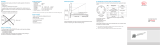
Fig. 1 Output characteristic of an eddy current long-stroke displacement sensor. Position of measuring tube:
start of measuring range

Page 9
Functional Principle, Technical Data
induSENSOR, EDS
2.2 Structure
A coil is arranged in the sensor rod, and is thus protected against environmental influences. The controller is
integrated in the sensor housing. Long-stroke displacement sensors are designed for measuring ranges from
75 to 630 mm.
Electrical connection:
- 4-pin Amphenol connector, type C164P compact, (EDS-...-S... model)
1
- 7-pin Binder connector, type 712 (EDS-...- S ...7... model)
- 5-pin connector, type CA02COM-E14S with bayonet lock (EDS-...-F... model)
- Axial braid (EDS-...-Z... model)
1) Previous model no longer available

Page 10
Functional Principle, Technical Data
induSENSOR, EDS
2.3 Technical Data
Model EDS
-75
EDS
-100
EDS
-160
EDS
-200
EDS
-220
EDS
-250
EDS
-260
EDS
-300
EDS
-370
EDS
-400
EDS
-500
EDS
-630
Series S S, F S, F S Z S, F Z S, F, Z Z S, F, Z S S, F
Measuring range mm 75 100 160 200 220 250 260 300 370 400 500 630
Resolution mm 0.038 0.05 0.08 0.1 0.11 0.125 0.13 0.15 0.18 0.2 0.25 0.315
Frequency response (-3 dB) 150 Hz
Measuring rate 600 Sa/s
Linearity
≤±0.3%
FSO/ mm
≤±0.23 ≤±0.3 ≤±0.48 ≤±0.6 ≤±0.66 ≤±0.75 ≤±0.78 ≤±0.9 ≤±1.1 ≤±1.2 ≤±1.5 ≤±1.89
Temperature stability ≤200ppmFSO/K
Supply voltage 18 ... 30 VDC
Max. current consumption 40 mA
Analog output
1
4 … 20 mA (load ≤ 500 Ohm)
Connection
S series 7-pin M9 screw/plug connection (Binder); axial, also radial (see accessories for connection cable)
F series Bayonet 5-pin screw/plug connection; radial (see accessories for connection cable)
Z series Integrated braids, axial
Temperature range
Storage -40 … +100 °C (-40 ... +212 °F)
Operation -40 … +85 °C (-40 ... +185 °F)
Pressure resistance 450 bar (front)
Shock (DIN EN 60068-2-27)
40 g / 6 ms in 3 axes, 1000 shocks each
100 g / 6 ms radial, 3 shocks each
300 g / 6 ms axial, 3 shocks each
Vibration (DIN EN 60068-2-6)
±2.5mm/5…44Hz,10cycleseach
±23g/44…500Hz,10cycleseach
Protection class (DIN EN 60529) IP65 (F series) / IP67 (S series) / IP40 (Z series)
Material Stainless steel (housing); Aluminum (measuring tube)
FSO = Full Scale Output
1) Optional voltage output (1 ... 5 V) with C703-5/U connection cable for EDS, S series
2) Models with plug connection only with suitable and connected mating plug

Page 11
Delivery
induSENSOR, EDS
3. Delivery
3.1 Unpacking, Included in Delivery
1 Eddy current long-stroke displacement sensor 1 O-ring (mounted on sensor)
1
1 Measuring tube 1 Test report
1 Assembly Instructions 1 5-pole cable connector (only for the F series)
Do not use the sensor rod to pick up or carry the eddy current long-stroke displacement sensors.
Sensor
housing
Carefully remove the components of the measuring system from the packaging and ensure that the
goods are forwarded in such a way that no damage can occur.
Check the delivery for completeness and shipping damage immediately after unpacking.
If there is damage or parts are missing, immediately contact the manufacturer or supplier.
3.2 Storage
- Temperature range: -40 ... +100 °C (-40 ... +212 °F)
- Humidity: 5 - 95 % (non-condensing)
- Atmospheric pressure
1) For S and F sensor models only

Page 12
Installation and Assembly
induSENSOR, EDS
4. Installation and Assembly
4.1 Precautions
The measuring tube must not contact the sensor rod during operation.
> Damage to or destruction of the sensor through abrasion is possible.
Do not deform or shorten the measuring tube.
> Loss of specified technical data.
Do not crush the O-ring or damage through sharp-edged items.
> Loss of functionality
4.2 Measuring Tube Guidance and Fastening
Mount the measuring tube flush in the piston bore, see Fig. 2.
The dimensions for the measuring tube can be found in the following figures, see Fig. 9 ff. The measuring
tube must not touch the sensor shaft when the piston is retracted. Note the measuring tube position at zero
point (= 4 mA output), see Fig. 3 ff.
> Improper measuring tube guidance can lead to increased wear and premature failure.
A slightly eccentric mounting of the measuring tube has no negative influence on the sensor signal.
Mount the measuring tube in the piston by means of pressing or glueing.
Spot clamping is not permissible.
i
The specified technical data only apply when the measuring tube supplied by MICRO-EPSILON is used!
Fig. 2 Positioning of measuring tube in the piston
Press measuring
tube flush into
piston

Page 13
Installation and Assembly
induSENSOR, EDS
a
a
Fig. 3 Zero point of the measuring tube, EDS- ... -S Fig. 4 Zero point of the measuring tube, EDS- ... -F
a
Measuring
range
Dimension
a
75 15 (0.59)
100 20 (0.79)
160 20 (0.79)
200 20 (0.79)
220 20 (0.79)
250 20 (0.79)
260 20 (0.79)
Fig. 5 Zero point of the measuring tube, EDS- ... -Z 300 20 (0.79)
370 25 (0.98)
400 25 (0.98)
500 25 (0.98)
630 25 (0.98)
Dimensions in mm (inches)

Page 14
Installation and Assembly |EDS- ... -S Model
induSENSOR, EDS
4.3 Sensor Mounting
4.3.1 EDS- ... -S Model
EDS-75-S EDS-100-S EDS-160-S EDS-200-S EDS-250-S EDS-300-S EDS-400-S
EDS-500-S EDS-630-S
Mount the sensor in the cylinder with a mounting ring, see Appendix Optional Accessories, and 6 cylin-
der head screws (M5 x 10).
Sealing is provided by a supplied O-ring on the sensor shaft.
Displacement
sensor
O-ring
Piston
Sensor shaft
CylinderSensor rod
21HB
Mounting ringM5x10 Measuring tube
Fig. 6 Sensor mounting in a hydraulic cylinder, EDS- ... -S model
Pressure chamber seal:
- O-ring: 18.5 x 1.5
- Material: Viton
Mounting hole for flange: 21H8 dia.
Borehole surface:
- R
a
= 0.8
- R
max
= 3.2
Dimension Tolerance
µm
21H8 +33
0

Page 15
Installation and Assembly |EDS- ... -S Model
induSENSOR, EDS
ø34 (1.4 dia.)
Bushing for
connector
15
(.6)
ø34 (1.4 dia.)
40 (1.6)
ø31 (1.2 dia.)
Suitable tool
Use a suitable tool for
mounting, see Fig. 7.
The bushing must be congruent
with the connector for models
with radial connector.
Fig. 7 Mounting of an induSENSOR, EDS- ... -S model
Groove
Suitable extractor
Dismantling
Use an suitable extractor
for dismantling, see Fig. 8.
Dimensions of the flange
groove: 1.5 x 1.5 mm
(0.06 x 0.06“,depth x width).
Fig. 8 Dismounting of an induSENSOR, EDS- ... -S model
Dimensions in mm (inches)

Page 16
Installation and Assembly |EDS- ... -S Model
induSENSOR, EDS
Dimensional drawing, EDS- ... -S model
32.5 (1.28)
4
+0.1
(.16
+0.1
)
8
-0.1
(.32
-0.004
)
ø34
-0.1
(1.34
-0.004
dia.)
ø21f7 (.83 dia.)
ø10 (.39 dia.)
1.5 (.06)
Sensor rod L
Measuring tube I
ø30 (1.18 dia.)
l
L
d
min 30
(1.18)
A
B
Fig. 9 induSENSOR with axial connector, EDS- ... -SA7 - I model,
measuring range: 75 / 100 / 160 / 200 / 250 / 300
Dimen-
sion
Tolerance
µm
A B
21f7
-20
-41
EDS-xxx-S-Sx-l
1
31 (1.2) 16 (.63)
EDS-xxx-S-Sx7-l 51 (2.0) 47 (1.85)
Dimensions in mm (inches)
1)
Previous model no longer available.
Measuring
range
Sensor
rod L
Measuring
tube I
Measuring
tube d
75
(2.95)
110
(4.33)
110
(4.33)
16
(.63)
100
(3.94)
140
(5.51)
140 (5.51)
16
(.63)
160
( 6.29)
200
(7.87)
200
(7.87)
16
(.63)
200
(7.87)
240
(9.45)
240
(9.45)
16
(.63)
250
(9.84)
290
(11.42)
290
(11.42)
16
(.63)
300
(11.81)
340
(13.39)
340
(13.39)
16
(.63)

Page 17
Installation and Assembly |EDS- ... -S Model
induSENSOR, EDS
13
(0.51)
A
Fig. 10 induSENSOR with radial connector, EDS- ... -SR7 - I model, measuring range: 75 (2.95) / 100 (3.94) /
160 (6.29) / 200 (7.87) / 250 (9.84) / 300 (11.81)
A
EDS-xxx-S-Sx-I
1
31 (1.2)
EDS-xxx-S-Sx7-I 51 (2.0)
Dimensions in mm (inches)
1) Previous version no longer available.

Page 18
Installation and Assembly |EDS- ... -S Model
induSENSOR, EDS
32.5 (1.28)
4
+0.1
(.16
+0.1
)
1.5 (.06)
Sensor rod L
Measuring tube I
ø30 (1.18 dia.)
ø12(.47 dia.)
d
16
-0,1
(.63
-0.004
)
l
L
ø21f7
(.83 dia.)
min 30
(1.18)
A
B
ø34
-0.1
(1.34
-0.004
dia.)
Fig. 11 induSENSOR with axial connector, EDS- ... -SA7 - I model, measuring range: 400 / 500 / 630
Dimension Tolerance
µm
A B
21f7
-20
-41
EDS-xxx-S-Sx-l
1
31 (2.19) 16 (.63)
EDS-xxx-S-Sx7-l 51 (2.1) 47 (1.85)
Measuring
range
Sensor rod Measuring tube
L I d
400 (15.74) 450 (17.72) 450 (17.72) 18 (.71)
500 (19.69) 550 (21.65) 550 (21.65) 18 (.71)
630 (24.80) 680 (26.77) 680 (26.77) 18 (.71)
Dimensions in mm (inches)
1) Previous version no longer available.

Page 19
Installation and Assembly |EDS- ... -S Model
induSENSOR, EDS
13
(0.51)
A
Fig. 12 induSENSOR with radial connector, EDS- ... -SR7 - I model, measuring range: 400 (15.74) / 500 (19.69)
/ 630 (24.80)
A
EDS-xxx-S-Sx-I
1
31 (1.2)
EDS-xxx-S-Sx7-I 51 (2.0)
Dimensions in mm (inches)
1) Previous version no longer available.

Page 20
Installation and Assembly |EDS- ... -F Model
induSENSOR, EDS
4.3.2 EDS- ... -F Model
EDS-100-F EDS-160-F EDS-200-F EDS-250-F EDS-300-F EDS-400-F EDS-630-F
Mount the sensor in the cylinder using 6 cylinder head screws (M8 x 6).
Sealing is provided by a supplied O-ring on the sensor shaft.
Sensor rod Cylinder Piston
Sensor shaft
Measuring tube
O-ring
Displacement
sensor
42F7
Cylinder head
screw M8
Fig. 13 Sensor mounting in a hydraulic cylinder, EDS- ... -F model
Pressure chamber seal:
- O-ring: 38 x 2.0
- Material: PUR
Mounting hole for flange: 42F7 dia.
Borehole surface:
- R
a
= 0.8
- R
max
= 3.2
Dimension Tolerance
42F7 +50
+25
/