Page is loading ...

Aqua Logic®, Inc.
8268 Clairemont Mesa Blvd. Suite 302 San Diego, CA 92111
Tel: (858) 292-4773 Fax: (858) 279- 0537 Email: [email protected] www.aqualogicinc.com
AQUA LOGIC’S DS AND MT SERIES WATER-COOLED CHILLER
INSTALLATION & OPERATING INSTRUCTIONS
Effective 1-1-05
Thank you for purchasing an Aqua logic water-cooled chiller. It has been designed and built to provide years of
reliable, trouble-free service. It provides precise water temperature control up to +/- 1.0°F (0.7°C) accuracy and
features a continuous LCD display of the current fluid temperature.
BEFORE INSTALLING THE CHILLER
READ BOTH WARRANTY AND INSTALLATION INSTRUCTIONS.

Aqua Logic®, Inc.
8268 Clairemont Mesa Blvd. Suite 302 San Diego, CA 92111
Tel: (858) 292-4773 Fax: (858) 279- 0537 Email: [email protected] www.aqualogicinc.com
WARNING!!!
THIS DEVICE USES HIGH VOLTAGE ELECTRICAL POWER FOR OPERATION.
SAFETY PRECAUTIONS MUST BE OBSERVED.
CAREFULLY READ AND OBSERVE THE FOLLOWING TO AVOID ELECTRICAL SHOCK
OR SEVERE DAMAGE TO THE CONTROLLER.
We recommend, as with all electrical equipment used in or around water, that you connect your electrical
equipment to a ground-fault interrupt (GFI) protection circuit.
ALWAYS turn the power off for the equipment at the source (circuit breaker) if there is any electrical
problem, the electrical equipment or controller has been submerged or sprayed with water.
ALWAYS make sure that the electrical circuit you connect your electrical equipment to is rated at least
20% higher than the maximum current rating on the equipment.
ALWAYS make sure that you operate the equipment and controller at the correct voltage.
Do NOT submerge controller in water.
Do NOT allow water to drip or spray on or into controller.
Do NOT attempt to turn off the power at the chiller or controller if a problem occurs. Disconnect unit at the
main power panel.
Do NOT attempt to repair equipment. Call Aqua Logic for instructions.
NOTICE:
Inspect the chiller for shipping damage. If damaged, contact Aqua Logic.

Aqua Logic®, Inc.
8268 Clairemont Mesa Blvd. Suite 302 San Diego, CA 92111
Tel: (858) 292-4773 Fax: (858) 279- 0537 Email: [email protected] www.aqualogicinc.com
Installation and Operating Instructions for DS and MT chiller
Start-up and installation:
WARNING: DO NOT over tighten water fittings.
Mount chiller on a flat cement pad and away for water spray.
Give at least 2 feet all the way around unit for servicing.
Install process water inlet and outlet.
Install condenser water inlet and outlet.
Test water fittings for leaks.
Apply electrical power to the chiller.
In cold weather below 60°F, allow approximately 4 hours for compressor oil warm-up.
Adjust the controller to the desired water temperature. (See "Operation and Programming")
Warning: This unit must have proper water flow rate both on the process and the
condenser to operate correctly.
Operation and programming:
Note: Controller has been pre-programmed by the factory for chiller operation. The
temperature is the only setting that needs to be changed.
STEP
ANNUNCIATOR DESCRIPTION
DISPLAY
1
F or C
Fahrenheit or Celsius Scale
F
2 S1 (blinking) Stage 1 Setpoint Temperature
S1
78
3 DIF1 (blinking) Stage 1 Differential
Temperature
DIF1
1
4
C1/H1
Stage 1 Heating Mode
C1

Aqua Logic®, Inc.
8268 Clairemont Mesa Blvd. Suite 302 San Diego, CA 92111
Tel: (858) 292-4773 Fax: (858) 279- 0537 Email: [email protected] www.aqualogicinc.com
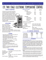
Liquid Crystal Display (LCD)
The LCD display provides a constant readout of the sensor temperature and indicates if the output relay is energized. When the S1
annunciator is constantly illuminated during operation, the relay is energized. The display is also used in conjunction with the keypad to allow
the user to adjust the setpoint temperature, differential and heating /cooling modes.
Programming Steps and Display
The control can be programmed in four simple steps using the LCD display and the three keys on the face of the control. (See photo for
display and keys.)
NOTE: Stage 1 must be set for heat mode and Stage 2 for cool mode for correct operation.
1. To start programming, press the SET key once to access the Fahrenheit/Celsius mode. The display will show the current status, either F
for degrees Fahrenheit or C for degrees Celsius. Then press either the up arrow or down arrow key to toggle between the F or C
designation.
2. Press the SET key again to access the chill mode setpoint temperature. The LCD will display the current setpoint temperature and the
S1 annunciator will be blinking to indicate that the control is in the setpoint mode. Press either the up key to increase or down key to
decrease the setpoint to the desired temperature.
3. Press the SET key again to access the heat mode differential temperature. The LCD will display the current differential and the DIF 1
annunciator will be blinking to indicate that the control is in the differential mode. Then press either up key to increase or the down
key to decrease the differential to the desired setting (minimum 1
4. Press the SET key again to select chill mode. The LCD will display the current mode: H1. Then press either up key to increase or the
down key to select the correct Stage 1 mode. Stage 1 MUST be in the H1 mode for correct operation.
5. Press the SET key again to access the heat mode setpoint temperature. The LCD will display the current heat setpoint temperature and
the S2 annuciator will be blinking to indicate that the control is in the setpoint mode. Then press either the up key to increase or down
key to decrease the setpoint to the desired temperature. S1 and S2 should both be set for the same temperature.
6. Press the SET key again to access the chill mode differential temperature. The LCD will display the current differential and the DIF 2
annunciator will be blinking to indicate that the control is in the differential mode. Then press either up key to increase or the down
key to decrease the differential to the desired setting (minimum 1°F, maximum 30 DIF1 and DIF2 should both be set to the same
value for best results.
7. Press the SET key again to access the heating mode. The LCD will display the current mode: C2 or H2 . Stage 2 MUST be in the C2
mode for correct operation.
8. Press the SET key again to exit programming mode. Controller will display current water temperature.
Controller will automatically drop out of “program mode” and return to “operating mode” 30 seconds after last key press.
Troubleshooting Controller Error Messages:
Display Messages
E1 - Appears when the up or down key is pressed when not in the programming mode.
To correct: If the E1 message appears even when no keys are being pressed, replace the control.
E2 - Appears if the control settings are not properly stored in memory.
To correct: Check all settings and correct if necessary.
EP - Appears when the probe and or flow switch is open , shorted or sensing a temperature that is out of range.
To correct: Check to see if the sensed temperature is out of range. If not , check for probe damage by comparing it to a known ambient
temperature between -30
is correct, flow switch.
EE - Appears if the EEPROM data has been corrupted.
To correct: This condition cannot be field repaired. Replace the control.
CL - Appears if calibration mode has been entered.
To correct: Remove power to the control for least five seconds. Reapply power. If the CL message still appears, replace the control.
/