Page is loading ...

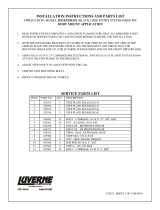
INSTALLATION INSTRUCTIONS AND PARTS LIST
MODEL 415114, GRIP STEPS (BOARDS ONLY)
UNIVERSAL APPLICATIONS
1. Read instructions completely and check to make sure that all required parts (listed on the
service parts list) are on hand before starting the installation
.
2. Follow the instructions included with the specific bracket package to mount the brackets to
your vehicle.
3. Step assembly:
3.1 This Board can be modified from its original length to fit many applications. Simply
determine how long you will need the board, and cut to that length using a saber saw,
chop saw, or hack saw. Use flat black paint to touch up the ends that were cut.
3.2 Before attaching the grip steps to the brackets, slide the appropriate number of support
braces (item #2) into the channel of the step (item #1).
3.3 Slide the end cap (item #3) over the front and rear of each step. Using the supplied #8 x
1/2” self drilling tek screw (item #8), screw the end cap to the bottom of the step.
4. Attaching the step to the mounting bracket:
4.1 Set the step on the mounting brackets, and slide each support brace over the top of each
mounting bracket. Attach the flat spacer plate (item #4) to the bottom of the step,
between the support brace, and the top of the mounting bracket.
4.2 Using the supplied 5/16-18 x 1” carriage bolt, washer, and flange nuts, (item #5, 6, 7),
attach the step assembly, flat spacer plate and mounting bracket. (NOTE: Some of the
flange nuts are supplied in the specific bracket package, not the step package.)
4.3 Set the step plate in the correct position and tighten all fasteners.
Torque all fasteners to 19 LB FT.
SERVICE PARTS LIST
ITEM PART NO. QTY DESCRIPTION
1 551888 2 EXTRUSION-AL,97.87,GRIP STEP,BLK,415098
1 551889 2 EXTRUSION-AL,101.25,GRIP STEP,BLK,415102
1 551388 2 EXTRUSION-AL,113.62,GRIP STEP,BLK,415114
2 551296 10 SUPPORT BRACE, UPPER, GALV.
3 551394 4 CAP-END,GRIP STEP, BLACK, PLASTIC
4 551298 14 SPACER PLATE, LOWER, BLACK
5 108683 20 BOLT-CRG,5/16-18 X 1.0”, SST
6 101369 20 WASHER-FLAT,5/16,SST
7 102680 20 NUT-SERR FLG,HX,SST,WX,5/16-18
8 107958 8 SCR-TEK #8-18 X 1/2”,SST,BLK
REV C 01APR12
REV B 03DEC10
REV A 10JUL09
551391 SHEET 1 OF 2 01JUN09


INSTALLATION INSTRUCTIONS AND PARTS LIST
APPLICATION: MODEL 401729/401728 W2W GRIP STEP BRACKETS ON:
2017+ FORD SUPER DUTY PICKUPS
NO DRILL APPLICATION
1. READ INSTRUCTIONS COMPLETELY AND CHECK TO MAKE SURE THAT ALL REQUIRED PARTS
(LISTED ON SERVICE PARTS LIST) ARE ON HAND BEFORE STARTING THE INSTALLATION.
2. ON THE LEFT SIDE OF THE VEHICLE INSTALL TWO 1.5” ISOLATOR WASHERS (ITEM #3), THE STEP
MOUNTING BRACKET (ITEM #2) AND TWO M8-1.25 FLANGE NUTS (ITEM #4) OVER THE FACTORY
PROVIDED STUDS ON THE INSIDE OF THE ROCKER PANEL AS SHOWN.
3. REPEAT STEP 2 FOR THE REAR BRACKET.
4. CHECK THAT THE FRONT AND REAR BRACKETS ARE LEVEL AND TIGHTEN ALL FLANGE NUTS.
NOTE: IF INSTALLING ON A REGULAR CAB PICKUP SKIP TO STEP #10.
5. REMOVE THE CENTER BODY MOUNT BOLT AND INSTALL THE CENTER INBOARD MOUNTING
BRACKET (ITEM #10) AS SHOWN IN FIGURE 1.
6. USING THREE 3/8”-18 X 1.0” HEX BOLTS (ITEM #5) THREE 3/8” FLAT WASHERS (ITEM #6) AND
THREE 3/8”-18 FLANGE NUTS (ITEM #7) ATTACH THE OUTBOARD BRACKET (ITEM #11) TO THE
INBOARD BRACKET (ITEM #10). ADJUST THE HEIGHT TO MATCH YOUR STEP BOARD AND
TIGHTEN BOLTS.
7. ASSEMBLE THE LOAD REACTION STUDS AND HARDWARE (ITEMS #6-9) AS FOLLOWS.
7.1. ON THE SHORT THREADED END OF THE LOAD REATION STUD (ITEM #9), INSTALL A 3/8”
FLANGE NUT (ITEM #7) BACKWARDS ONTO THE BOTTOM OF THE THREAD. THEN INSTALL A
3/8” FLAT WASHER (ITEM #6) AND RUBBER CUSHION WASHER (ITEM #8) TIGHT UP AGAINST
THE FLANGE NUT. (THE END OF THE STUD MUST BE RECESSED IN THE RUBBER WASHER
APPOX. 3/16”)
7.2. ON THE LONG THREADED END OF THE STUD, INSTALL A 3/8” FLANGE NUT (ITEM #7)
BACKWARDS TO NEAR THE BOTTOM OF THE THREADS.
8. CHECK THAT THE CENTER BRACKET IS PERPENDICULAR TO THE BODY OF THE VEHICLE AND
TIGHTEN THE BODY MOUNT BOLT PER THE MANUFACTURES SPECIFICATIONS.
9. INSTALL THE LOAD REACTION STUD INTO THE CENTER INBOARD BRACKET (ITEM #10) AS
SHOWN IN FIGURE 1 AND ADJUST THE INBOARD NUT SO THAT THE RUBBER CUSHION WASHER
IS SNUG UP AGAINST THE FRAME OF THE VEHICLE. INSTALL A 3/8” FLANGE NUT (ITEM #7) ON
THE OUTBOARD SIDE OF THE STUD AND TIGHTEN TO 19 LB-FT.
10. LOOSEN THE NUT AND BOLT ON THE SPRING SHACKLE JUST ENOUGH TO SLIP THE REAR
INBOARD BRACKET (ITEM #12) BEHIND THE NUT AS SHOWN IN FIG 2.. NOTE: ON THE PASSENGER
SIDE THE NUT WILL HAVE TO BE LOOSENED, AND THE BOLT SLID OUTWARD IN ORDER TO
INSTALL THE MOUNTING BRACKET. DO NOT REMOVE THE BOLT COMPLETELY AS THIS
COULD RESULT IN INJURY. ADJUST THE BRACKET SO THAT IT IS VERTICAL AND TIGHTEN TO
80 LB-FT.
REV B 18JAN17
REV A 30DEC16
553107 SHEET 1 OF 3 06OCT16

11. USING TWO 5/16-18 X 1” BOLTS (ITEM #16) TWO 5/16 FLAT WASHER (ITEM #15) AND TWO 5/16-18
FLANGE NUTS (ITEM #17) INSTALL THE OUTBOARD BRACKET (ITEM #14) AS SHOWN IN FIGURE 2.
NOTE: LEAVE THIS BRACKET LOOSE AT THIS TIME.
12. ATTACH THE STEP BOARD TO THE MOUNTING BRACKETS AS DESCRIBED IN THE INSTRUCTION
SHEET INCLUDED WITH YOUR STEP BOARD ASSEMBLY.
13. ADJUST THE REAR OUTBOARD BRACKET FOR YOUR STEP ASSEMBLY AND TIGHTEN THE BOLTS
SECURING THE OUTBOARD BRACKET TO THE INBOARD BRACKET.
14. REPEAT STEPS 2 – 13 FOR THE RIGHT SIDE OF THE VEHICLE.
SERVICE PARTS LIST
ITEM PART NO. QTY DESCRIPTION
1 1 STEP ASSY, GRIP STEP
2 552845 4 BRACKET-MTG, GRIP STEP, 401729
2 553168 4 BRACKET-MTG, GRIP STEP, 401728
3 108442 8 WASHER – NYLON, .36” X 1.5” X .032” BLACK
4 105859 8 NUT- FLANGE, M8-1.25, ZP
5 100040 6 BOLT-HEX HD, 3/8”-16 X 1.00”, ZP
6 100062 8 WASHER-FLAT, 3/8”, ZP
7 106995 12 NUT-FLANGE, 3/8”-16, ZP
8 102592 2 WASHER-RUBBER, .354 X 1.0 X .75
9 104673 2 STUD-DBL END, 3/8”-16 X 5”
10 552843 2 BRKT-MTG, CTR, INBOARD, 401729
10 553169 2 BRKT-MTG, CTR, INBOARD, 401728
11 552844 2 BRKT-MTG, CTR, OUTBOARD, 401529
12 553102 1 BRKT-MTG, REAR, W2W, INBOARD, LH, 401729
12 553170 1 BRKT-MTG, REAR, W2W, INBOARD, LH, 401728
13 553103 1 BRKT-MTG, REAR, W2W, INBOARD, RH, 401729
13 553171 1 BRKT-MTG, REAR, W2W, INBOARD, RH, 401728
14 552125 2 BRKT-MTG, REAR, W2W, OUTBOARD,
15 106998 4 WASHER-FLAT, .375X.875X.083, BZP
16 106997 4 SCR-HEX, 5/16-18 X 1.0”, BZP
17 106996 4 NUT-FLANGE, 5/16-18, BZP
REV B 18JAN17
REV A 30DEC16
553107 SHEET 2 OF 3 06OCT16

/