Page is loading ...


OPERATING AND INSTRUCTION MANUAL
Index
AS 201÷751 FC
1
ENGLISH
EN
The data in this manual are not binding and may be changed by the manufacturer without notice. Reproduction of this manual, even partial, is strictly prohibited.
I
NDEX
INDEX .................................................................................................................................................. 1
GENERAL INFORMATION.................................................................................................................... 3
1.1 Terminology..................................................................................................... 3
1.2 Symbols ........................................................................................................... 3
1.3 How to interpret the model .............................................................................. 4
1.4 How to interpret the code................................................................................. 4
1.5 How to interpret the alphanumeric string-code ............................................... 4
TECHNICAL DATA, PERFORMANCE AND OPERATING LIMITS........................................................... 6
2.1 Performance ..................................................................................................... 6
2.2 Sound Level Measurements............................................................................. 6
SAFETY................................................................................................................................................ 7
3.1 General............................................................................................................. 7
3.2 General precautions ......................................................................................... 7
3.2.1 Liquids to be cooled ......................................................................................... 7
3.2.2 Lifting and carriage precautions ...................................................................... 7
3.2.3 Installation precautions .................................................................................... 7
3.2.4 Precautions during operation .......................................................................... 8
3.2.5 Maintenance and repair precautions ............................................................... 8
3.3 Refrigerant gases.............................................................................................. 8
3.3.1 Safety schedule ................................................................................................. 9
DESCRIPTION .................................................................................................................................... 10
4.1 Operating principle ........................................................................................ 10
4.2 Cooling circuit .............................................................................................. 10
4.2.1 Compressors ................................................................................................... 10
4.2.2 Condensers ..................................................................................................... 10
4.2.3 Fans ................................................................................................................ 10
4.2.4 Evaporator ...................................................................................................... 10
4.3 Hydraulic circuit ............................................................................................ 11
4.3.1 Free-Cooling coils .......................................................................................... 11
4.4 Hydraulic group ............................................................................................. 11
4.4.1 Casing ............................................................................................................. 12
4.4.2 Protection rating ............................................................................................ 12
4.5 Electrical circuit............................................................................................. 12
4.6 Overall dimensions ........................................................................................ 12
INSTALLATION .................................................................................................................................. 13
5.1 Inspection....................................................................................................... 13
5.2 Positioning ..................................................................................................... 13
5.3 Indoor installation: minimum distances from walls ...................................... 13
5.4 Antifreeze protection ..................................................................................... 13
5.5 Hydraulic connections ................................................................................... 13
5.6 Electrical connections .................................................................................... 15
5.7 Phase Monitor ................................................................................................ 15
START UP .......................................................................................................................................... 16
ADJUSTMENT AND CONTROL ........................................................................................................... 17
7.1 Forced ventilation of the electrical board ...................................................... 17
7.2 Electric panel heater....................................................................................... 17
7.3 Circulation pump ........................................................................................... 17
7.3.1 Pump antifreeze function ................................................................................ 18
7.4 Automatic re-start .......................................................................................... 18
7.5 Compressor integral protection (PI) .............................................................. 18
7.6 Water pressure gauge..................................................................................... 18
7.7 High pressure switches .................................................................................. 18
7.7.1 AS 201÷ 301 FC high pressure switch ........................................................... 18
7.7.2 AS 351÷ 751 FC pressure switches ................................................................ 18
7.8 Pressure transducers....................................................................................... 19
7.9 Fan speed regulation ...................................................................................... 19
7.10 Water differential pressure switch ................................................................. 19
7.11 Level sensor ................................................................................................... 20
OPERATION AND MAINTENANCE ..................................................................................................... 21

OPERATING AND INSTRUCTION MANUAL
Index
AS 201÷751 FC
2
ENGLISH
EN
The data in this manual are not binding and may be changed by the manufacturer without notice. Reproduction of this manual, even partial, is strictly prohibited.
8.1 Operation........................................................................................................21
8.2 Maintenance ...................................................................................................21
8.2.1 Access to the inside of the machine ................................................................21
8.2.2 Maintenance Schedule ...................................................................................22
TROUBLE SHOOTING.........................................................................................................................23

OPERATING AND INSTRUCTION MANUAL
General information
AS 201÷751 FC
3
ENGLISH
EN
The data in this manual are not binding and may be changed by the manufacturer without notice. Reproduction of this manual, even partial, is strictly prohibited.
C
HAPTER
1
G
ENERAL
INFORMATION
1.1 Terminology
This manual is written for those responsible for the installation, use and maintenance of the unit.
The machines described in this manual are called “WATER CHILLERS” or simply “CHILLERS”.
These chillers have been designed to cool a liquid flow.
In most applications, the liquid to be cooled is water and the term “WATER” will be used even if the liquid to be cooled is different from water (e.g. a mixture of
water and glycol as foreseen in these units).
The liquid to be cooled must be compatible with the materials used.
This analysis must be made before purchasing or installing the unit.
Here below the term “PRESSURE” will be used to indicate the gauge pressure.
All parts of the text which are important for the SAFETY of persons and property are written in bold face and highlighted by the symbol shown here on the right.
This symbol is also printed near the title of sections or paragraphs concerning safety.
ATTENTION
This manual provides the user, installer and maintenance technician with all the technical information required for installation, operation
and carrying out routine maintenance operations to ensure long life.
If spare parts are required, this must be original.
Requests for SPARE PARTS and for any INFORMATION concerning the unit must be sent to the distributor or to the nearest service centre,
providing the MODEL and SERIAL NUMBER shown on the machine data plate and on the first page of this manual.
1.2 Symbols
The following symbols are shown on the stickers on the unit as well as on the overall dimension drawing and refrigeration circuits in this manual. Their meaning
is the following:
Machine water-inlet Machine water-outlet
Indications for lifting the unit Water drainage point from the machine
Electrocution risk Cooling air flow (for air-cooled units)
Direction of the refrigerant fluid Rotation direction of the pump (if installed)
and of the fans
Risk of injury from sharp edges Risk of burns from contact with high-
temperature surfaces
Presence of pulleys and belt in motion inside
casing
Hole for inserting bars for lifting the
machine

OPERATING AND INSTRUCTION MANUAL
General information
AS 201÷751 FC
4
ENGLISH
EN
The data in this manual are not binding and may be changed by the manufacturer without notice. Reproduction of this manual, even partial, is strictly prohibited.
1.3 How to interpret the model
1.4 How to interpret the code
* Max. ambient temperatures referred to a water outlet temperature of 10°C.
1.5 How to interpret the alphanumeric string-code
The alphanumeric string-code is reproduced on the metallic plate of the main page of this manual.
MODEL DESCRIPTION
AS FCX X X
Version of the unit (N, SN or SSN)
Free Cooling version
Number of circuits (always 1)
Compressors nominal power in HP
Aries Model
/N Low noise operation value: standard. Compressors compartment only partially acoustically insulated.
/SN Available from AS 351 FC to AS 751 FC:
Low noise operation value: medium. Acoustically insulated compressors compartment.
/SSN Available from AS 351 FC to AS 751 FC:
Low noise operation value: high. Compressors compartment with high efficiency acoustic insulation.
The illustrated symbol at the right side of the page, is the same symbol found on specific areas of the
chiller and electrical wiring diagrams. The magnified section shown, is also part of the same
alphanumeric string-code present on the main page of this manual.
In the magnified section, the value above (X) is called “position” and the box below (Y) is the value given
to that position.
At the left side is marked an example of an empty alphanumeric string-code.
Each position will be defined by an alphanumeric value (0, 1, 2, A, B, etc.).
Specific unit features are established by the position and the alphanumeric
values.
Please find below each position’s alphanumeric values explained, which can
be used:

OPERATING AND INSTRUCTION MANUAL
General information
AS 201÷751 FC
5
ENGLISH
EN
The data in this manual are not binding and may be changed by the manufacturer without notice. Reproduction of this manual, even partial, is strictly prohibited.
POS. VALUE DESCRIPTION
VOLTAGE 1 0 400/3/50
CUSTOMISING 2-3 A STANDARD
VERSION 4-5-6 N N
SN SN
SSN SSN
REFRIGERANT 7 1 R407C
AMBIENT MINIMUM TEMPERATURE 8 0 STANDARD
2-15°C
EVAPORATOR 9 B SHELL AND COIL
CFINS COIL
ELECTRONIC THERMOSTATIC VALVE 10 0 NO
1YES
HYDRAULIC GROUP 11 0 NONE
1P2
2P2+P2
3STORAGE + P2
4 STORAGE + P2+P2
6P3
7P3+P3
8STORAGE + P3
9 STORAGE + P3+P3
CSTORAGE + P4
(only AS 201÷301 FC)
D STORAGE + NOT PUMP
(only AS 201÷301 FC)
COMPRESSORS COCKS 12 0 NO
1YES
CONDENSING COILS PROTECTION 13 0 NONE
1FILTERS
FANS REGULATION 14 1 ELECTRONIC CONTROL
2 BY STEPS
CORRECTION CAPACITOR 15 0 NO
1YES
PHASE MONITOR 16 A YES
REMOTE CONTROL 17 B NO
CSIMPLE
COMPRESOR CASING RESISTANCE 18 1 YES

OPERATING AND INSTRUCTION MANUAL
Technical data, performance and operating limits
AS 201÷751 FC
6
ENGLISH
EN
The data in this manual are not binding and may be changed by the manufacturer without notice. Reproduction of this manual, even partial, is strictly prohibited.
C
HAPTER
2
T
ECHNICAL
DATA
,
PERFORMANCE
AND
OPERATING
LIMITS
The main technical data are given on the machine data plate.
2.1 Performance
The chiller performance mainly depends on the flow and temperature of the cooled water and on the ambient temperature.
These data are defined during the offer stage and it is to these that reference should be made.
2.2 Sound Level Measurements
* at distance of 1 metre (3,2 FT)
** global
Test conditions
Noise levels refer to operation of the unit at full load in nominal conditions.
Sound pressure level in hemispherical irradiation conditions at a distance of 1 m (3,2 FT) from the condenser side of the unit and height of 1.6 m (5,2 FT) from
the ground. Values tolerance ± 2 dB.
Sound power level: in compliance with ISO 3744.
MODEL and CODE Identifies the size of the machine (see chapter " General information") and the type of
construction which distinguishes it.
MANUAL Code number of this manual.
SERIAL NUMBER This is the construction number of the unit.
YEAR OF CONSTRUCTION This is the year of the final test of the machine.
VOLTAGES/PHASES/FREQUENCY Power supply specifications.
MAX. CONSUMPTION
I
MAX
This is electrical current consumed by the unit during the limit working conditions.
INSTALLED POWER
P
MAX
It is the power absorbed by the unit during the limit working conditions.
PROTECTION RATING Protection rating of the whole machine, as defined in European standard EN 60529.
REFRIGERANT This is the refrigerant fluid in the unit.
COOLANT CHARGE Quantity of coolant fluid filled in the plant.
MAX. REFRIGERANT PRESS. HP SIDE Refrigerant circuit designed pressure of the high pressure side
MAX. REFRIGERANT PRESS. LP SIDE Refrigerant circuit designed pressure of the low pressure side
COOLING FLUID USED Fluid cooled by the machine (normally water).
MAX. WORKING PRESSURE Maximum design pressure of the user circuit.
MAX. TEMPERATURE Maximum design temperature of the user circuit, absolutely not to be confused with the
maximum working temperature which is defined in the offer.
SOUND PRESSURE LEVEL Sound pressure level in a free field in hemispherical irradiation conditions (open field)
at a distance of 1 m from the machine, condenser side, and at 1.6 m from the ground.
AMBIENT TEMPERATURE Minimum and maximum value of the cooling air temperature.
WEIGHT This is the approximate weight of the unit before packing.
Model AS 201 FC AS 251 FC AS 301 FC AS 351 FC AS 401 FC
Version N SN SSN N SN SSN N SN SSN N SN SSN N SN SSN
Lp dB(A) * 75.2 - - 75.2 - - 76.5 - - 77.6 71.2 63.9 76.6 70.0 63.9
Lw dB(A) ** 88.2 - - 88.2 - - 89.5 - - 90.6 84.2 76.9 89.6 83.0 76.9
Model AS 501 FC AS 551 FC AS 601 FC AS 701 FC AS 751 FC
Version N SN SSN N SN SSN N SN SSN N SN SSN N SN SSN
Lp dB(A) * 76.6 70.0 62.7 76.6 70.0 63.7 76.6 70.0 63.7 77.3 70.2 64.1 77.3 70.2 64.1
Lw dB(A) ** 89.6 83.0 75.7 89.6 83.0 76.7 89.6 83.0 76.7 90.3 83.2 77.1 90.3 83.2 77.1

OPERATING AND INSTRUCTION MANUAL
Safety
AS 201÷751 FC
7
ENGLISH
EN
The data in this manual are not binding and may be changed by the manufacturer without notice. Reproduction of this manual, even partial, is strictly prohibited.
C
HAPTER
3
S
AFETY
ATTENTION
This machinery was designed to be safe in the use for which it was planned provided that it is installed, started up and maintained in
accordance with the instructions contained in this manual.
The manual must therefore be studied by all those who want to install, use or maintain the machinery.
The machine contains electrical components which operate at the line voltage, and also moving parts, as fans.It must therefore be isolated
from the electricity supply network before being opened.
Maintenance operations involving work inside the machine must be performed by skilled and adequately qualified personnel equipped with
suitable protection means (active and passive, e.g. work gloves) ton ensure work in maximum safety.
3.1 General
When handling or maintaining the unit and all auxiliary equipment, the personnel must operate with care observing all instructions concerning health and safety
at installation site.
Most accidents which occur during the operation and maintenance of the machinery are a result of failure to observe basic safety rules or precautions. An
accident can often be avoided by recognising a situation that is potentially hazardous.
The user should make sure that all personnel concerned with operation and maintenance of the unit and all auxiliary equipment have read and understood all
warnings, cautions, prohibitions and notes written in this manual as well as on the unit.
Improper operation or maintenance of the unit and auxiliary equipment could be dangerous and result in an accident causing injury or death.
Do not operate the unit and auxiliary equipment until the instructions in the Operating section of this manual are understood by all personnel
concerned.
Do not carry out any servicing, repair or maintenance work on the unit and auxiliary equipment until the instructions in the relevant sections of this
manual are clearly understood by all personnel concerned.
We cannot anticipate every possible circumstance which might represent a potential hazard. The warnings in this manual are therefore not all-inclusive. If the
user employs an operating procedure, an item of equipment or a method of working which is not specifically recommended, he must ensure that the unit and
auxiliary equipment will not be damaged or made unsafe and that there is no risk to persons or property.
Any improper use of the machine will relieve the manufacturer from any liability for possible personal injury or property damage.
Arbitrary modifications made to the unit will automatically invalidate all forms of guarantee provided by the manufacturer.
3.2 General precautions
3.2.1 Liquids to be cooled
The liquids to be cooled must be compatible with the materials used.
These can be water or mixtures of water and glycol, for example.
The addition of anti-corrosive chemical additives and operating in a pH range between 7 and 8 is recommended.
Even in the case of glycol mixtures, the use of appropriate chemical additives (consult the glycol supplier) is very important to protect the unit materials from
possible corrosion caused by the chemical degradation to which glycol is subject.
The use of chemical additives is necessary when any part of the hydraulic circuit the unit is part of is open to the atmosphere. In this case, in fact, the continuous supply
of oxygen facilitates possible corrosive reactions inside the unit.
The liquids to be cooled must not be flammable.
If the liquids to be cooled or warmed cannot be discharged into the sewers because of the presence of dangerous substances (e.g. ethylene glycol) the unit must
be installed in a place provided with a collection system for any liquid which leaks without letting it reach the sewers. This collection system must be able to
contain the entire volume of liquid in the hydraulic circuit.
Furthermore, when the unit is no longer used, dangerous liquids must be disposed of by firms specialised and authorised for treating them.
3.2.2 Lifting and carriage precautions
Avoid injury by using a hoist to lift heavy loads. Check all chains, hooks, shackles and slings are in good condition and are of the correct capacity. They must be
tested and approved according to local safety regulations. Cables, chains or ropes must never be applied directly to lifting eyes. Always use an appropriate
shackle or hook properly positioned. Arrange lifting cables so that there are no sharp bends.
Use a spreader bar to avoid side loads on hooks, eyes and shackles. When a load is on a hoist stay clear of the danger area beneath and around it. Keep lifting
acceleration and speed within safe limits and never leave a load hanging on a hoist for longer than is necessary.
The units must be handled in accordance with the plans shown in the annexed drawing.
The manufacturer does not supply bars, belts and lifting hooks with the unit.
3.2.3 Installation precautions
Installation work must be carried out by competent personnel under a qualified supervisor.
See overall dimension drawings.
The electrical supply line of the unit must be protected by equipment chosen and installed by the user as described in the wiring diagram as well as in the
paragraph "5.6 Electrical connections".
If the unit is connected to a closed-type hydraulic circuit fitted with an automatic filling system, and the pressure of the filling system exceeds the maximum
working pressure of the unit, it is necessary to install a pressure limiter device (e.g. a safety valve which operates at a lower pressure than the maximum working
pressure of the machine, and located close to the input connection).
All the piping of the cooled water or cooling water must be painted or clearly marked in compliance with the local safety provisions in the place of installation.
Equip the unit with some manual interception valves to be able to lock the hydraulic circuit in the event of maintenance operations.
On-off valves should be provided for the chiller so that the hydraulic circuit can be by-passed to carry out maintenance.
All the electrical connections must comply with the local provisions in the place of installation.
The machine and the auxiliary apparatus must be earthen and protected against short-circuits and overloading.

OPERATING AND INSTRUCTION MANUAL
Safety
AS 201÷751 FC
8
ENGLISH
EN
The data in this manual are not binding and may be changed by the manufacturer without notice. Reproduction of this manual, even partial, is strictly prohibited.
If raised platforms are required to provide access to the unit they must not interfere with normal operation or obstruct access for lifting or dismantling
components. Platforms and stairs should be of grid or plate construction with safety rails on all open sides.
If the unit is installed in the open air, ensure that it is not exposed to very strong winds.
These can be dangerous for two reasons, in fact:
• they could reduce the stability of the metal structure of the machine and could damage the anchoring of the panels of the casing;
• they could negatively influence the performance of the condenser.
3.2.4 Precautions during operation
Operation must be carried out by competent personnel under a qualified supervisor.
Never remove or tamper with the safety devices, guards or insulation materials fitted to the unit or auxiliary equipment.
When mains power is switched on, lethal voltages are present in the electrical circuits and extreme caution must be exercised whenever it is necessary to carry
out any work on the electrical system.
Do not exceed the flow of liquid to be cooled specified in paragraph "5.5 Hydraulic connections".
3.2.5 Maintenance and repair precautions
Maintenance, overhaul and repair work must be carried out by competent personnel under a qualified supervisor.
ATTENTION
The non-insulated surfaces of the components of the cooling circuits inside the compressor compartment can be at very high temperatures
when the machine is in operation and for some minutes after it is turned off.
This creates the danger of burns for those who enter the compartment.
When disposing of parts and waste material of any kind make sure that there is no pollution of any drain or natural water-course and that no burning of waste
takes place which could cause pollution of the air.
Protect the environment by using only approved methods of disposal.
If replacement parts are needed use only original spares.
Keep a written record of all maintenance and repair work carried out on the unit and auxiliary equipment.
The frequency and the nature of the work required over a period can reveal adverse operating conditions which should be corrected.
Use only refrigerant gas specified on the specification plate of the unit.
Make sure that all instructions concerning operation and maintenance are strictly followed and that the complete unit, with all accessories and safety devices, is
kept in good working order.
The accuracy of pressure and temperature gauges must be regularly checked.
They must be renewed when acceptable tolerances are exceeded.
Keep the machine clean at all times.
Protect components and exposed openings by covering them, for example, with clean cloth or tape during maintenance and repair work.
Do not weld or carry out any operation which produces heat near a system which contains oil or flammable liquids.
The systems which may contain oil or flammable liquids must be completely drained and cleaned (with steam, for example), before carrying out these operations.
Never weld, nor modify in any way, a vessel which may be put under pressure.
To prevent an increase in working temperature, inspect and clean heat transfer surfaces (i.e. condenser fins) regularly.
For every unit establish a suitable time schedule for cleaning operations.
Avoid damage to safety valves and other pressure relief devices.
Avoid plugging by paint, oil or dirt accumulation.
Precautions must be taken when carrying out welding or any repair operation which generates heat, flames or sparks.
The adjacent components must always be screened with non-flammable material and if the operation is to be carried out near any part of the lubrication system,
or close to a component which may contain oil, the system must first be thoroughly purged, preferably by steam cleaning.
Never use a light source with an open flame to inspect any part of the machine.
Before dismantling any part of the unit ensure that all heavy movable parts are secured.
When a repair has been completed, make sure no tools, loose parts or rags are left in, or on the machine.
Check the direction of rotation of electric motors (fans, compressors and pump with three phase supply) when starting up the unit initially and after any work on
the electrical connections or switch gear.
All guards must be reinstated after carrying out repair or maintenance work.
Do not use flammable liquid to clean any component during operation.
If chlorinated hydrocarbon non-flammable fluids are used for cleaning, safety precautions must be taken against any toxic vapours which may be released.
Before removing any protection panel from the power board or dismantling any of its parts, carry out the following operations:
• Isolate the unit from the main electrical power supply. Lock the isolator in the “OFF” position and remove the fuses (if they are present).
• Attach a label to the isolator switch and display a panel carrying warning “WORK IN PROGRESS - DO NOT APPLY VOLTAGE”. Do not switch on
electrical power or attempt to start the unit if a warning label is attached.
Coloured tracers can be used in service-maintenance operations.
Inspect all refrigerant circuit joints including connectors, flanges, and more generally all critical points (open joints) in order to prevent possible leakage of
refrigerant gas.
3.3 Refrigerant gases
R407C is used as refrigerant gas in these units.
Never attempt to mix refrigerant gases.
To clean out a very heavily contaminated refrigerant system, e.g. after a refrigerant compressor burnout, a qualified refrigeration engineer must be consulted to
carry out the task.
The manufacturer's instructions and local safety regulations should always be observed when handling and storing high pressure gas cylinders.

OPERATING AND INSTRUCTION MANUAL
Safety
AS 201÷751 FC
9
ENGLISH
EN
The data in this manual are not binding and may be changed by the manufacturer without notice. Reproduction of this manual, even partial, is strictly prohibited.
3.3.1 Safety schedule
R407C
Denomination: 23% Difluoromethane (R32);
25% Pentafluoroethane (R125);
52% R134a
INDICATION OF THE DANGERS
Major dangers: Asphyxia
Specific dangers: Rapid evaporation can cause freezing
FIRST AID MEASURES
General information: Do not give anything to unconscious persons
Inhalation: Take the person outdoors. Use oxygen or artificial respiration if necessary. Do not administer adrenaline or
similar substances
Contact with the eyes: Thoroughly wash with plenty of water for at least 15 minutes and call a doctor
Contact with the skin: Wash immediately with plenty of water. Remove contaminated clothing immediately
FIRE-FIGHTING MEASURES
Means of extinction: Any means
Specific dangers: Pressure increase
Specific methods: Cool the containers with water sprays
MEASURES IN THE EVENT OF ACCIDENTAL LEAKAGE
Individual precautions: Evacuate personnel to safe areas. Provide adequate ventilation. Use means of personal protection
Environmental precautions: Evaporates
Cleaning methods: Evaporates
HANDLING AND STORAGE
Handling
technical measures/ precautions: Ensure sufficient air change and/or extraction in the work areas
recommendations for safe use: Do not inhale vapours or aerosols
Storage: Close properly and store in a cool, dry well-ventilated place. Store in its original containers. Incompatible
products: explosives, flammable materials, organic peroxide
CONTROL OF EXPOSURE/INDIVIDUAL PROTECTION
Control parameters: AEL (8-h e 12-h TWA) = 1000 ml/m3 for each of the three components
Respiratory protection: For rescue and maintenance work in tanks, use autonomous breathing apparatus. The vapours are heavier than
air and can cause suffocation, reducing the oxygen available for breathing
Protection of the eyes: Safety goggles
Protection of the hands: Rubber gloves
Hygiene measures: Do not smoke
PHYSICAL AND CHEMICAL PROPERTIES
Colour: Colourless
Odour: Similar to ether
Boiling point: -43.9°C at atm. press.
Flammability point: Non flammable
Relative density: 1.138 kg/l at 25°C.
Solubility in water: Negligible
STABILITY AND REACTIVITY
Stability: No reactivity if used with the relative instructions
Materials to avoid: Alkaline metal, earthy alkaline metals, granulated metals salts, Al, Zn, Be, etc. in powder
Hazardous decomposition products: Halogen acids, traces of carbonyl halides
TOXICOLOGICAL INFORMATION
Acute toxicity: (R32) LC50/inhalation/4 hours/lab. rats >760 ml/l
(R125) LC50/inhalation/4 hours/lab. rats >3480 mg/l
(R134a) ALC/inhalation/4 hours/lab. rats = 567 ml/l
Local effects: Concentrations substantially above the TLV can cause narcotic effects. Inhalation of products in
decomposition can lead to respiratory difficulty (pulmonary oedema)
Long-term toxicity: Has not shown any cancerogenic, teratogenic or mutagenic effects in experiments on animals
ECOLOGICAL INFORMATION
Global warming potential HGWP (R11=1): R125: 0.84 - R134a: 0.28
Ozone depletion potential ODP (R11=1): 0
CONSIDERATIONS ON DISPOSAL
Usable with reconditioning

OPERATING AND INSTRUCTION MANUAL
Description
AS 201÷751 FC
10
ENGLISH
EN
The data in this manual are not binding and may be changed by the manufacturer without notice. Reproduction of this manual, even partial, is strictly prohibited.
C
HAPTER
4
D
ESCRIPTION
4.1 Operating principle
All the machines described in this manual work on the basis of the same principle.
The ARIES Free Cooling chillers are air condensed monobloc units, equipped with helicoidal fans, Scroll compressors and finned coils for the Free-Cooling
system to cool the process water.
The Free-Cooling system is activated when the ambient temperature is lower than the chiller inlet water temperature. In this way the process water can be cooled,
partially or completely, exploiting the low ambient temperature in order to save energy (the refrigerant compressors and the condensing fans stop completely or
partially)
The coils of the Free-Cooling system have their own fans that work separately from the ones of the Chiller condensing coils.
The refrigerant circuit is single, and it cools water flow using a single shell and coil evaporator, in which, on one side, the refrigerant fluid evaporates (coil
side), and on the other side the liquid to be cooled flows (shell side).
The refrigerant compressors are controlled by an electronic control unit.
4.2
Cooling circuit
See enclosure
The ARIES FREE-COOLING units have a single refrigerant circuit and two compressors.
The refrigerant in the gaseous state is compressed by the compressor and sent to the condenser.
Here the gas condenses, exchanging heat with the ambient air.
It exits in a liquid state.
It flows through the cock and the dryer filter. After passing the flow indicator, the liquid is laminated by the thermostat valve and enters the evaporator.
Here it exchanges heat with the water circuit as it evaporates.
Having returned to the gaseous state, it is sucked in by the compressor/s and the cycle is repeated.
Information relating to the components of the standard machine are given below.
Components other than standard ones may be used to meet particular requirements.
In this case please refer to offer data.
4.2.1 Compressors
The compressors used are of the SCROLL type.
They are provided with integral protection against excessive-temperatures in the electric motor windings, a check valve in the delivery line and a by-pass
between intake and delivery.
Cocks can be provided on the inlet ad outlet lines, on request.
In the machines equipped with two compressors (per circuit), each circuit is provided with an oil-balancing pipe.
Each circuit is provided with an oil-balancing pipe.
In silenced versions (SN and SSN) the compressors are installed on vibration-damping devices and find in a acoustic insulated compressor site.
ATTENTION
The first time the machine is started after several days’ stoppage, turn on the casing resistance of every compressor at least 6 hours before
pressing the ON/OFF button.
4.2.2 Condensers
Condensers are heat exchangers, fin pack type, and several fans produce the air that flows over them.
The tubes are in copper and the fins in aluminium.
The shoulders are in galvanised carbon steel.
The refrigerant circuit includes a condensing coil and its proper row of fans.
4.2.3 Fans
Axial fans feature die-cast aluminium impellers with sickle-shaped blades.
The fans are protected to IP54.
All fans belong to insulation class F which ensures they work outdoors in all weather conditions.
The assembly is completed with an aerodynamic galvanised sheet steel mouth and safety grilles downstream of the air flow.
4.2.4 Evaporator
The units can be equipped with a finned coil evaporator or with a shell and coil evaporator.
Finned-coil evaporator in models from AS 201 FC to AS 301 FC:
The evaporators are of finned coil type with copper tubes and aluminium fins; the water flows in contact with the fins, while the refrigerant fluid flows through
the tubes. This models are always equipped with an accumulation tank.
Shell and coil evaporator in models from AS 351 FC to AS 751 FC:
The evaporator consists of a U-type pipe-bundle exchanger in which the coolant fluid, that comes from the refrigerant circuit, evaporates removing heat from the
water to be cooled which flows on the plating side.
The water connections are with threading, from model AS 201 FC to model AS 601 FC.
From model AS 701 FC they are of “Victaulic” type.
They can be easily reached by the external of the chiller.It is provided with a cock to facilitate the discharge of the water contained in it when you want to drain
the plant (see chapter " Operation and maintenance").
The evaporator is protected against freezing caused by low evaporating temperatures of antifreeze function of the electronic board which controls the water
outlet temperature. Moreover, from model AS 351FC, each evaporator is equipped with a differential pressure switch that protects the evaporator against the
absence of water.

OPERATING AND INSTRUCTION MANUAL
Description
AS 201÷751 FC
11
ENGLISH
EN
The data in this manual are not binding and may be changed by the manufacturer without notice. Reproduction of this manual, even partial, is strictly prohibited.
ATTENTION
The fluid flow rate which flows on the plating side must not exceed the values specified in the table of paragraph "5.5 Hydraulic
connections".
4.3 Hydraulic circuit
The hydraulic circuit is equipped with the following components:
• Evaporator
• water process inlet/outlet connections of victaulic type
• three-way-valve with proportional control to change the hydraulic circuit operation from Standard to Free-Cooling
• Free-cooling coils
• Automatic valves to leack the air
• Water discharging cocks
4.3.1 Free-Cooling coils
They are fins coils composed of copper pipes and manifolds and of aluminium fins.
The pipes are smooth inside, while the fins are corrugated.
The coils are equipped with manual breather valves for the air, and with water discharging cocks to empty the coils.
4.4 Hydraulic group
AS 201÷301 FC UNITS
These units are equipped with a tank, inside which there is the evaporator finned coil. The P2 or P4 pump can be installed on request.
AS 351÷751 FC UNITS
On request the units can be equipped with the hydraulic group, which has a centrifugal pump and an accumulation tank.
Furthermore there are the following devices:
• expansion tank
• water safety valve
• automatic air vent valve
• emptying valve
• water pressure gauge on pump delivery
• automatic charge group:
pressure reducer
manometer
interception cock.
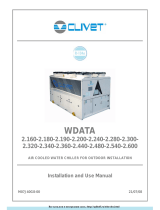
FREE-COOLING
COIL
CONDENSING
COIL
EVAPORATOR

OPERATING AND INSTRUCTION MANUAL
Description
AS 201÷751 FC
12
ENGLISH
EN
The data in this manual are not binding and may be changed by the manufacturer without notice. Reproduction of this manual, even partial, is strictly prohibited.
On request the units can be furnished with an higher lift pump.
NOTE
The pump must never run dry.
4.4.1 Casing
The casing is built with galvanised panels and painted with polyester resins.
4.4.2 Protection rating
The protection rating of the machine is IP54 with F insulating class, to assure a good unit’s operation in the event of external installation.
4.5 Electrical circuit
See the enclosed wiring diagrams.
4.6 Overall dimensions
See enclosure

OPERATING AND INSTRUCTION MANUAL
Installation
AS 201 - 751 FC
13
ENGLISH
EN
The data in this manual are not binding and may be changed by the manufacturer without notice. Reproduction of this manual, even partial, is strictly prohibited.
CHAPTER 5
INSTALLATION
ATTENTION
Before carrying out the installation or operating on this machine, ensure that all the personnel has read and understood the chapter "
Safety" in this manual.
5.1 Inspection
Immediately after uncrating, inspect the unit.
5.2 Positioning
1. The unit may be installed both outdoors and indoors.
2. If installed indoors, the room must be well ventilated. In some cases it may be necessary to install fans or extractors to limit the temperature of the
room.
3. The ambient air must be clean and not contain flammable gas or solvents.
4. The minimum and maximum working ambient temperature are specified on the unit data plate. In extreme temperature conditions, the protection
devices may trip.
5. The machine must be installed on a perfectly horizontal flat surface, built and calculated to withstand the machine’s operating weight, especially in
the contact points highlighted in the installation drawing. In the event of installations which fail to comply with the above requirements, the
manufacturer’s warranty cover will immediately become null and void.
6. Leave the necessary space around the unit to permit access during service operations (see enclosures).
7. Do not obstruct or disturb the flow of cooling air of the condenser. The air must enter the machine through the finned batteries of the condensers to
be expelled to the exterior through the fans. Position the unit in such a way that the cooling air cannot recirculate in the intake grilles. Ensure that
the unit is not subject to warm air from the cooling systems of other machines.
8. Do not install the unit in a place where there may be dangerous strong winds.
5.3 Indoor installation: minimum distances from walls
See enclosure
5.4 Antifreeze protection
The performances of the Aries free-cooling units take into consideration the use of a mixture of water and glycol at 30%.
The glycol percentage can be chanced, but MTA suggests the use of a mixture of water and glycol in order to prevent the formation of ice and breakings.
Depending on the cooled water outlet temperature, antifreeze (ethylene glycol) must be added in the following percentages to prevent the formation of ice:
ATTENTION
Freeze protection setpoint set at 5°C. To lower the freeze protection setpoint, modify mask Q3.
5.5 Hydraulic connections
1. Connect the unit to the water piping as indicated in the drawing below.
2. Provide two cocks (inlet and outlet) to by-pass the machine for maintenance purposes without having to empty the water circuit by the user.
3. If the unit doesn’t have a pump, make sure that the pump installed by the user has the intake directly connected to the unit so that the pressure on the
plating side in the evaporator is not too high.
Ambient temperature up to [°C] Ethylene Glycol [% in weight]
00
-5 15
-10 25
-15 30
-20 40
Water outlet temperature up to [°C] Ethylene Glycol [% in weight]
40
019
-5 27
-10 34
-15 39
-20 44

OPERATING AND INSTRUCTION MANUAL
Installation
AS 201÷751 FC
14
ENGLISH
EN
The data in this manual are not binding and may be changed by the manufacturer without notice. Reproduction of this manual, even partial, is strictly prohibited.
The hydraulic system must be dimensioned so that water doesn’t flow in the machine with pressure values in excess of the value on the specification plate and
flows greater than those set out in the table below:
NOTE
To prevent pumps breakings install a water filter on the unit water inlet.
The non-observance of this rule, could cause serious damages to the evaporator.
NOTE
The pump must never run dry.
“VICTAULIC” CONNECTION
A tightening jaws
B sealing gasket
C stub pipe to weld
D evaporator stub pipe
EVAPORATOR
Maximum flow [m
3
/h]
AS 201 FC 18
AS 251 FC 18
AS 301 FC 27
AS 351 FC 21
AS 401 FC 21
AS 501 FC 25
AS 551 FC 30
AS 601 FC 30
AS 701 FC 41
AS 751 FC 41

OPERATING AND INSTRUCTION MANUAL
Installation
AS 201÷751 FC
15
ENGLISH
EN
The data in this manual are not binding and may be changed by the manufacturer without notice. Reproduction of this manual, even partial, is strictly prohibited.
5.6 Electrical connections
The connection of the unit to the power supply network must be done in conformity with the laws and prescriptions in force in the installation place.
The power supply voltage, the frequency and the phase number must be as shown on the unit data plate. The power supply voltage must not be, also for short
periods, out of the tolerances given in the wiring diagram. Except for different indications, the frequency tolerance is +/-1% of the nominal value (+/-2% for
short periods).
In the event of three-phase supply, the system must be symmetrical (equal effective voltage values and equal phase angles among consecutive phases). In
particular, except for different indication, the max. unbalance between each phase is 2%. The unbalance is calculated as following:
Vavg = average of voltage phases
The phase conductor and the neutral wire must not be confused.
For the electrical supply:
1. E connect the unit (PE terminal in the electrical panel) to the earthed system of the building.
2. E guarantee the automatic interruption of the power supply in the event of insulation failure (protection against indirect contacts in compliance
with IEC 364) by means of a differential device (normally with operation nominal current of 0.03 A).
3. at the beginning of the electrical supply cable must be guaranteed a protection against direct contacts with a protection degree of IP2X or IPXXB
at least (reference CEI EN 60529).
4. at the beginning of the electrical supply cable must be installed protection devices that protect against overcurrents (short circuit) (see information
in the electrical wiring).
5. use conductors which transform the max. current required to the max. operating ambient temperature, according to the selected installation type
(IEC 60364-5-523) (see information in the electrical wiring).
6. it must be installed a safety device which limits the 17 kA peak short circuit current to its own nominal cut-off power when the short circuit current
at the operation point is higher than 10 kA effective.
Indications of electrical wiring:
• max. size permitted for the fuse type gG.
In general, the fuses can be replaced with an automatic switch regulated by means of the unit max. absorbed current (contact the manufacturer
if necessary)
• section and type of the power supply cable (if not already supplied):
installation: insulated conductors, multipolar cable in duct, in air or over masonry (C type in compliance with IEC 60364-5-523 1983) or
without no other cable in contract
working temperature: the max. working ambient temperature of the unit
cable type: copper conductors, PVC insulation from 70°C (if not specified) or EPR insulation from 90°C
To check the correct connection of the unit to the electrical net see chapter " Start up".
5.7 Phase Monitor
The electronic controller, with the aid of a Phase Monitor (see unit wiring diagram), enables to control unit electric power feeding, stopping the unit in case of
incorrect phase sequence or phase failure.
Tripping of the Phase Monitor stops the unit and the relative alarm is displayed.
Some measure of instability on the power feeding line can be considered to be normal.
If the frequency of unit shut-downs caused by Phase Monitor tripping should increase, contact your electricity company in order to solve the problem.
ATTENTION
It is strictly prohibited to tamper with the Phase Monitor.
Max difference of aech phase from Vavg
Vavg 100

OPERATING AND INSTRUCTION MANUAL
Start up
AS 201÷751 FC
16
ENGLISH
EN
The data in this manual are not binding and may be changed by the manufacturer without notice. Reproduction of this manual, even partial, is strictly prohibited.
C
HAPTER
6
S
TART
UP
ATTENTION
Before starting up or operating these units be sure that all personnel have read and understood the chapter " Safety" of this manual.
1. Check that the machine on/off valves are open.
2. If the hydraulic circuit is of the closed type, check that an expansion tank has been installed with an adequate capacity.
3. Check that the ambient temperature is within the limits indicated on the machine data plate.
4. Check that the main switch is in the OFF position (“O”).
5. Check that the power supply voltage is correct.
6. Power the machine by means of the supply line protection device.
7. Turn the machine main switch ON (“I”).
The led or the control panel display ON indicate that the machine is powered (see
p
CO manual attached).
8. Models without pump:
Before turning on the machine, check that the water circuit pump is operating and that the water is flowing through the evaporator.
9. Models with output cocks on the compressors:
Check that the output cocks of the compressors are open.
10. Press g + h buttons on the board. The pump, if installed, starts immediately.
After the delay set on the electronic board (see enclosed
p
CO manual) the refrigerant compressors will start. The first time the machine is started-
up after several days’ stoppage, turn the main circuit breaker to the on position (“I”) and wait at least 6 hours before starting the machine by means
of the ON/OFF button on the board (if the compressors casing resistances are present.
11. Compressors, pumps and fans have only one correct rotation direction.
If a SCROLL compressor does not turn in the correct direction, it runs very noisily and does not compress.
A fan rotates in the correct direction if it sucks air from inside the machine. The machines are built and tested so that the rotation directions of the
three above-mentioned components are in agreement. Therefore, if one component rotates in the correct direction, the others are also correctly
connected.
Check the rotation directions of the above-mentioned components when starting up the first time and after every maintenance operation. If all the
components are rotating incorrectly, invert two of the phases at the main power terminals in the power board. If, on the other hand, one or more of
the components is not rotating in the proper direction, carry out this operation at the terminals of the corresponding contactor/s (see attached
wiring plan).
12. If with the first start-up, there is a high ambient temperature and the temperature of the water in the hydraulic circuit is much higher than the working
value (e.g. 25-30°C) this means that the chiller starts up overloaded with the consequence of possible tripping of the protection devices. To reduce this
overload, a chiller outlet valve can be gradually (but not totally!) closed to reduce the flow of water passing through it. Open the valve as the water
temperature in the hydraulic circuit reaches the working value.

OPERATING AND INSTRUCTION MANUAL
Adjustment and control
AS 201÷751 FC
17
ENGLISH
EN
The data in this manual are not binding and may be changed by the manufacturer without notice. Reproduction of this manual, even partial, is strictly prohibited.
C
HAPTER
7
A
DJUSTMENT
AND
CONTROL
7.1 Forced ventilation of the electrical board
All units are equipped with a fan thermostat system in the electric board.
The circulation fan is controlled by a thermostat positioned inside the electrical panel. It starts when the temperature inside the electrical panel exceeds the
thermostat’s set point.
The setpoint value is 40°C.
The differential value, 4°C, is fixed.
7.2 Electric panel heater
The electric panel of the units designed to work until -15°C, is fitted with a fan-assisted heater, which has to keep a suitable ambient temperature inside the
panel, in order to prevent the components from low temperature.
This heater is controlled by a thermostat inside the electric panel which activates it when the temperature inside the panel falls below the set point less the
differential.
The setpoint value is 5°C.
The differential value, 4°C, is fixed.
7.3 Circulation pump
OPTIONAL
The circulation pump can be installed in all units, only if requested.
Its installation can be performed following different configurations already described in chapter " Description".
When the machine is turned on by means of the ON-OFF button the LED lights up and the pump (if installed) starts and remains on until the machine is turned
off by means of the ON-OFF button.
The pump (installed as optional) only stops with the following
p
CO alarm messages:
NOTE
The pump must never run dry.
Lack of water flow
Pump overload
Wrong phase sequence in power supply
ON
OFF
Electrical panel fan state
DIFFERENTIAL (Fixed)
SETPOINT
Temperature Temperature inside
the electrical panel
ON
OFF
Electric panel heater status
DIFFERENTIAL (fixed
)
SETPOINT
Temp e rat ure
Temperature inside
the electrical panel

OPERATING AND INSTRUCTION MANUAL
Adjustment and control
AS 201 - 751 FC
18
ENGLISH
EN
The data in this manual are not binding and may be changed by the manufacturer without notice. Reproduction of this manual, even partial, is strictly prohibited.
7.3.1 Pump antifreeze function
The unit is furnished with a pump antifreeze function. It starts the pump when the ambient temperature is lower than the value fixed by pCOelectronic control.
ATTENTION
Freeze protection setpoint set at 5°C. To lower the freeze protection setpoint, modify mask
Q3
.
NOTE
To lower the freeze protection setpoint, contact the MTA after-sales service and add a suitable amount of antifreeze solutions to the system
(see chap. 5.4 “Antifreeze protection” ).
7.4 Automatic re-start
After a loss of power, the unit will re-start automatically if it was ON, but not if it was OFF before the loss of power.
7.5 Compressor integral protection (PI)
This protection consists of the combination of the magnetothermic switch and the compressor protection.
This system ensures complete protection against most of the problems which can give rise to burning of the windings.
When it trips, it is necessary to find and eliminate the cause; then you can start the machine again by pressing ON-OFF button.
7.6 Water pressure gauge
OPTIONAL
It can be installed as optional, depending on the pump installation.
If, on demand, the pump has been installed, also the water pressure gauge will be installed on the unit rear panel.
It will indicate the water pressure at pump outlet with pump running and the pressure of the hydraulic circuit with pump stopped.
7.7 High pressure switches
7.7.1 AS 201÷ 301 FC high pressure switch
1. It is installed to monitor the refrigerant compressor discharge pressure and prevents it increasing to levels dangerous to the operation of the unit
and people within the vicinity.
It is of “manual reset” type.
Its intervention is detected by the electronic control that will display the alarm and will disactivate the relay output. Furthermore the pressure
switch will cut the current of the compressor winding, (see pCO manual).
When the compressor delivery pressure drops below the reset point, it automatically re-arms.
It will be possible to start again the unit following the alarm reset procedure in the pCO manual.
Remove the alarm trip cause, otherwise this cycle will repeat continuously.
The pressure switches HP should be screwed to the cooling circuit piping using a SCHRAEDER valve (with needle) which prevent leakage during the pressure
switch replacement.
The TRIP and RESET values of the above pressure switches depend upon the refrigerant gas, see the table below:
7.7.2 AS 351÷ 751 FC pressure switches
They assure a supplementary protection of electromechanical type in addition to the protection furnished by the
p
CO transducers.
They are installed to monitor the refrigerant compressor discharge pressure and prevents it increasing to levels dangerous to the operation of the unit and people
within the vicinity.
• Mod. AS 401 ÷ 751 FC:
Each unit is furnished with a high pressure switch for each circuit of “manual reset” type.
When it trips, it opens the compressor supply circuit (see wiring diagram).
Then, when the compressor delivery pressure drops below the reset point, it must be manually re-armed and it is possible to start the machine
again by means of the ALARM button of the electronic control.
• Mod. AS 351 ÷ 751 FC:
Each unit is furnished with a high pressure switch, associated to each refrigerant circuit. It is of “automatic reset” type.
When it trips, it opens the compressor supply circuit (see wiring diagram).
Then, when the compressor delivery pressure drops below the reset point, it automatically re-arms and it is possible to start the machine again
by means of the ALARM button of the electronic control.
The pressure switches HP should be screwed to the cooling circuit piping using a SCHRAEDER valve (with needle) which prevent leakage during the pressure
switch replacement.
The TRIP and RESET values of the above pressure switches depend upon the refrigerant gas, see the table below:
COMPONENT Refrigerant
TRIP RESET
bar °C °F bar °C °F
High pressure switch with automatic reset
(pressure cartridge type) R407C 27.2 63.4 146.1 20.5 51.5 124.7
COMPONENT Model Refrigerant
TRIP RESET
bar °C °F bar °C °F
High pressure switch with manual
reset AS 401 ÷ 751 FC R407C 26.7 62.6 144.7 22.7 55.7 132.3
High pressure switch with
automatic reset AS 351 ÷ 751 FC R407C 26.3 61.9 143.4 20.3 51.1 129.2
/