Page is loading ...

Visit www.trailfx.com or 1 (866) 638-4870 for Warranty Information / Tech Support / Product Updates.
2021 Keystone Automotive Operations Inc. All Rights Reserved. 12/08/2021-R01 Page-1 - 13
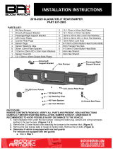
APPLICATION: 2019 –Chevrolet Silverado 1500
Assembly, Installation, Operation and
Maintenance Instructions
Full Replacement Front Bumper
Part Number:
FX3024
240 minutes
Dealer / Installer:
Provide a copy of these instructions to the end user of this product. These instructions
provide important operating and safety information for proper usage of this product.
Demonstrate the proper use of the product with the end user. Have the end user
demonstrate that they understand the proper use of the product.
End User:
Read
and follow all instructions included in this manual. Ask your Dealer / Installer for
assistance if you do not understand the proper use of the product. Never remove any
decals from the product. Failure to follow these instructions can result in injury or death.
WARNING
PARTS LIST:
Qty
Part Description
Qty
Part Description
1
Front Bumper Assembly
8
12mm x 40mm Bolt Plates
1
Driver/left Frame Mounting Bracket
2
12
-1.75mm x 120mm x 36mm Hex Bolts
1
Passenger/right Frame Mounting Bracket
10
12
-1.75mm x 50mm Hex Bolts
2
Left Facing Support Brackets
32
12mm x 32mm x 3mm Flat Washers
2
Right Facing Support Brackets
20
12mm Nylon Lock Nuts
1
Intercooler Cover
2
8mm Clip
-on Nuts
1
Driver/left Shutter Relocation Bracket
2
8
-1.25mm x 25mm Hex Bolts
1
Passenger/right Shutter Relocation Bracket
2
8mm x 24mm x 2mm Flat Washers
2
Plastic Plugs for License Plate
2
8mm Lock Washers
4
Sensor Retaining Clips
10
6
-1.00mm x 25mm Hex Bolts
4
20mm x 2mm Foam Washer
20
6mm x 18mm x 1.6mm Flat Washers
4
15.5mm x 24mm x 2mm Foam Sensor Seal
10
6mm Nylon Lock Nuts
4
Rubber Sensor Plugs
8
4mm x 10mm Button Head Bolts
3
Wire Harness Extensions
1
4mm Wrench
1
Sensor Cover Kit
1
2.5mm Wrench
Torque Specs
12mm 70 ft/lbs
8mm 20 ft/lbs
6mm 102 in/lbs
4mm 27 in/lbs
Factory See Mfg.

Visit www.trailfx.com or 1 (866) 638-4870 for Warranty Information / Tech Support / Product Updates.
2021 Keystone Automotive Operations Inc. All Rights Reserved. 12/08/2021-R01 Page-2 - 13
INSTALLATION PROCEDURE:
REMOVE CONTENTS FROM BOX. VERIFY ALL PARTS ARE PRESENT. READ INSTRUCTIONS
CAREFULLY BEFORE STARTING INSTALLATION. ASSISTANCE IS RECOMMENDED TO AVOID
POSSIBLE INJURY OR DAMAGE TO THE VEHICLE.
1. Open the hood and remove the plastic cover from the top of the grille and radiator, (Figure 1).
Models with grille mounted camera, unplug camera. Next, remove the screws attaching the grille to
the radiator core support. Once all hardware has been removed, firmly pull the grille straight out from
the vehicle to release the grille from the clips, (Figure 2). Place grille on a clean, soft surface.
2. Remove the license plate and bracket. On models with factory fog lights and/or bumper sensors,
unplug the wiring harness leading to the bumper, (Figure 3).NOTE: Wiring harness connector is
located up and behind the passenger/right side of the bumper. Release clips attaching
passenger/right fender liner to access plug for harness. Move harness away from bumper.
3. From behind the driver/left side of the bumper, remove the outer bumper support connected to the
side of the frame and the outer end of the bumper, (Figure 4).
4. Locate and remove the hex bolts attaching the bottom of the bumper to the bumper bracket attached
to the end of the frame, (Figure 4).
5. Repeat Steps 3 & 4 to remove the passenger/right bumper support and lower bumper hardware.
6. Move back to the top of the bumper. Pull back the end of the rubber cover between the bumper and
the bottom of the radiator to expose the bolts attaching the top of the bumper bracket to the frame
bracket, (Figure 5).

Visit www.trailfx.com or 1 (866) 638-4870 for Warranty Information / Tech Support / Product Updates.
2021 Keystone Automotive Operations Inc. All Rights Reserved. 12/08/2021-R01 Page-3 - 13
INSTALLATION PROCEDURE CONTINUED:
7. Place blocks or jack stands under the front bumper to support it during mounting bolt removal. Once
the bumper has been safely supported, remove the bumper bolts attaching the bumper assembly to
the top of the bumper bracket, (Figure 5).WARNING! Assistance is required to hold the bumper in
place during bolt removal to prevent the bumper from falling. Carefully slide the bumper assembly
with brackets off of the ends of the frame.
8. Remove both bumper brackets and tow hooks from the end of the frame, (Figures 6 & 11).
7. On diesel models only: Remove lower plastic splash guard and shroud, (Figures 7 & 8).
8. Unplug and remove the lower shutter assembly, (Figure 9).
9. Remove the shutter mechanism from the outer housing, (Figure 10).
9. Reinstall the plastic grille, camera if equipped and cover removed in Step 1,(Figure 12).
10. Select (1) Left Facing and (1) Right Facing Support Bracket. Starting on the driver/left side, attach
the Left Facing Support Bracket to the outer facing side of the frame with (2) 12mm Bolt Plates, (2)
12mm Flat Washers and (2) 12mm Nylon Lock Nuts, (Figures 13 &14). Next, attach (1) Right
Facing Support Bracket to the inner facing side of the frame with (2) 12mm Bolt Plates, (2) 12mm
Flat Washers and (2) 12mm Nylon Lock Nuts, (Figures 13 &15).Do not tighten hardware at this
time.
11. Select the driver/left Frame Mounting Bracket, (Figure 16). Reuse the (3) factory bumper bolts to
attach the top mounting holes on the Mounting Bracket to the threaded bumper mount. Attach the (2)
lower holes in the Mounting Bracket to the (2) Support Brackets with (2) 12mm x50mm Hex Bolts,
(4) 12mm Flat Washers and (2) 12mm Nylon Lock Nuts, (Figures 16 &18).Do not fully tighten
hardware.
12. Select (1) tow hook if equipped. Reuse the (1) short factory hex bolt to attach the rear mounting hole
in the tow hook to the Frame Bracket. Use the included longer (1) 12mm x120mm Hex Bolt, (2)
12mm Flat Washers and (1) 12mm Nylon Lock Nut to attach the front of the tow hook to the Frame
Bracket, (Figures 17 &18). Fully tighten tow hook hardware only at this time.
13. Repeat Steps 10—12 to install the passenger/right Support Brackets, Frame Bracket and tow hook.
14. Diesel models with lower shutter assembly only, (models without lower shutter assembly skip to
Step 15).
a. Insert (1) 8mm Clip Nut into the triangle shaped hole in the end of the frame on the bottom,
(Figure 19). Line up the Nut on the Clip Nut with the round hole directly behind the triangle
hole.
b. Select the driver/left Relocation Bracket, (Figure 20). Attach the Bracket to the Clip Nut with
(1) 8mm x25mm Hex Bolt, (1) 8mm Lock Washer and (1) 8mm Flat Washer. Repeat to attach
the passenger/right Relocation Bracket.
c. Attach the shutter assembly to the top mounting holes only in the Relocation Brackets with the
included (2) 6mm x25mm Hex Bolts, (4) 6mm Flat Washers and (2) 6mm Nylon Lock Nuts,
(Figures 20 &21).IMPORTANT, attach shutter mechanism to back of Relocation Brackets.
Do not fully tighten hardware at this time.
d. Select the Lower Shutter Cover. Temporarily remove the (2) bottom inner 12mm Hex Bolts
attaching the Frame Brackets to the inner Support Brackets, (see Step 11). Reuse the 12mm
Hardware to attach the top of the Cover to front of the Frame Brackets, (Figure 22).
e. Attach the bottom of the Cover to the front of the Shutter Relocation Brackets with the included
(2) 6mm x25mm Hex Bolts, (4) 6mm Flat Washers and (2) 6mm Nylon Lock Nuts, (Figure
22).
f. Fully tighten all shutter mounting hardware at this time. Plug shutter mechanism into wire
harness.

Visit www.trailfx.com or 1 (866) 638-4870 for Warranty Information / Tech Support / Product Updates.
2021 Keystone Automotive Operations Inc. All Rights Reserved. 12/08/2021-R01 Page-4 - 13
INSTALLATION PROCEDURE CONTINUED:
15. Determine if the vehicle is equipped front sensors:
Models without bumper sensors:
a. Select the included (4) Rubber Plugs.
b. From behind bumper, push plugs into sensor mounting holes, (Figure 23). Screws have been
provided to lock the plugs in the sleeve. Use is optional.
Models with bumper mounted sensors:
a. Disassemble front bumper to unplug and remove sensors and wiring harness from bumper.
b. Select (1) sensor. Remove the silicone seal from the end of the sensor. Slide the included
larger Foam Sensor Seal over front of sensor, (Figure 24).
c. Insert sensor with Seal into sensor mount, (Figure 25).
d. Place Foam Washer over end of sensor. Push Sensor Retaining Clip into sensor mount and
lock into mounting holes, (Figure 25).
e. Repeat previous Steps to install remaining sensors.
f. Install wiring harness for sensors, (Figure 27).NOTE: Use the included (3) Wiring Harness
Extensions to extend the harness to reach all sensor mounts as necessary.
g. Optional: Secure each sensor to the socket with (2) 4mm x10mm Button Head Screws,
(Figure 8).IMPORTANT: Sensors fit snug in sockets. The 4mm Screws are used to apply
slight pressure to lock the sensors in place. Tighten both screws evenly until they touch the
sensor body only. Do not overtighten screws or damage to sensors will result.
16. Models with factory fog lights:
a. Remove the passenger/right fog light assembly from the factory bumper.
b. Flip the fog light upside down. Use the included (3) 6mm x25mm Hex Bolts, (6) 6mm Flat
Washers and (3) 6mm Nylon Lock Nuts to attach the fog light to the tabs on the back of the
driver/left side of the Bumper, (Figures 26 &27).IMPORTANT: Attach the passenger/right
fog light to the driver/left side of the Bumper. Attach the driver/left for light to the
passenger/right side of the Bumper.
c. Fully tighten all fog light hardware. Plug wiring harness into fog lights, (Figure 27).
17. With assistance, position the Bumper Assembly up to the frame. Temporarily support the weight of
the Bumper. WARNING:To avoid possible injury or damage to the vehicle, do not proceed until the
Bumper is fully and safely supported.
18. Line up the (3) slots in the driver/left side mounting plate on the back of the Bumper with the (3) slots
in the Mounting Bracket. Attach the Bumper to the Bracket with the included (3) 12mm Hex Bolts, (6)
12mm Flat Washers and (3) 12mm Nylon Lock Nuts, (Figures 28 &29). Repeat this Step to attach
the passenger/right side of the Bumper to the Bracket, (Figure 29).
19. Level and adjust the Bumper and fully tighten all hardware.
20. Models with grille mounted camera, remove center screen from Bumper, (Figure 30).
21. If front license plate is required, insert (2) Plastic Plugs into the square holes in the front of the
Bumper. Reuse the factory screws to attach the license plate to the Plastic Plugs, (Figure 30).
22. Do periodic inspections to the installation to make sure that all hardware is secure and tight.

Visit www.trailfx.com or 1 (866) 638-4870 for Warranty Information / Tech Support / Product Updates.
2021 Keystone Automotive Operations Inc. All Rights Reserved. 12/08/2021-R01 Page-5 - 13
INSTALLATION PROCEDURE IMAGES:
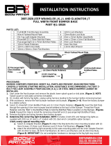
(Fig 1) Remove cover and screws
attaching grille (Fig 2) Firmly pull grille straight out
from vehicle
(Fig 3) Reach in through the
passenger/right fender liner to
locate and unplug wiring harness
leading to front bumper (arrow)
(Fig 4) Remove outer bumper
supports (arrow)
(Fig 5) Pull back cover to locate top
bumper bolts (Fig 6) Remove factory bumper
brackets and tow hooks if equipped

Visit www.trailfx.com or 1 (866) 638-4870 for Warranty Information / Tech Support / Product Updates.
2021 Keystone Automotive Operations Inc. All Rights Reserved. 12/08/2021-R01 Page-6 - 13
INSTALLATION PROCEDURE IMAGES CONTINUED:
(Fig 7) Diesel equipped only:
Remove forward splash guard (arrow)
(Fig 8) Diesel equipped only:
Remove the shroud from in front of
shutter assembly.
NOTE: The pins are located under the
plastic cover (arrow).
WARNING! Do not crawl under bumper
unless the bumper is properly supported
on blocks or stands or it may fall.
(Fig 9) Diesel equipped only:
Remove the bolts and pins attaching
the shroud to the vehicle (arrow).
Unplug and remove shutter assembly
(Fig 10) Diesel equipped only:
Remove the shutter assembly from
the outer housing

Visit www.trailfx.com or 1 (866) 638-4870 for Warranty Information / Tech Support / Product Updates.
2021 Keystone Automotive Operations Inc. All Rights Reserved. 12/08/2021-R01 Page-7 - 13
INSTALLATION PROCEDURE IMAGES CONTINUED:
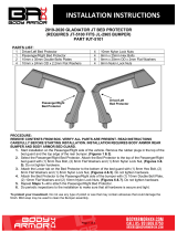
(Fig 11) Brackets and tow hooks
removed (Fig 12) Reinstall grille and cover
12mm Bolt Plate
12mm Flat Washer
12mm Nylon Lock Nut
(Fig 13) Insert Bolt Plates into open
end of frame. Attach left facing and
right facing Support Brackets to frame
and Bolt Plates
(Fig 14) Left facing Support Bracket
installed
(Fig 15) Right facing Support Bracket
installed

Visit www.trailfx.com or 1 (866) 638-4870 for Warranty Information / Tech Support / Product Updates.
2021 Keystone Automotive Operations Inc. All Rights Reserved. 12/08/2021-R01 Page-8 - 13
INSTALLATION PROCEDURE IMAGES CONTINUED:
(2) 12mm x 50mm Hex Bolts
(4) 12mm Flat Washers
(2) 12mm Nylon Lock Nuts
Reuse Factory
bumper bolts
(Fig 16) Reuse factory bumper bolts
to attach top of Frame Bracket to
bumper mount on frame
Reuse (1) factory hex bolt
(1) 12mm x 120mm Hex Bolt
(2) 12mm Flat Washers
(1) 12mm Nylon Lock Nut (Fig 17) Attach factory tow hook to
Bracket
(Fig 18) Driver/left Frame Bracket and
tow hook installed. Model without
shutter assembly pictured
(Fig 19) Slide 8mm Clip Nut into triangle
hole and over round hole (arrow)

Visit www.trailfx.com or 1 (866) 638-4870 for Warranty Information / Tech Support / Product Updates.
2021 Keystone Automotive Operations Inc. All Rights Reserved. 12/08/2021-R01 Page-9 - 13
INSTALLATION PROCEDURE IMAGES CONTINUED:
6mm x 25mm Hex Bolt
(2) 6mm Flat Washers
6mm Nylon Lock Nut 8mm Clip
Nut
(Fig 20) Attach driver/left shutter
Relocation Bracket to 8mm Clip Nut in
bottom of frame. Attach shutter
assembly to top mounting holes
8mm x 25mm Hex Bolt
8mm Lock Washer
8mm Flat Washer
(Fig 21) Attach shutter assembly to
back of Relocation Brackets
(Fig 22) Attach Cover to front of
Frame Bracket. Attach bottom of
Cover to lower mounting hole in
Relocation Bracket and shutter
assembly
6mm x 25mm Hex Bolt
(2) 6mm Flat Washers
6mm Nylon Lock Nut
See Figure 16
12mm x 50mm Hex Bolt
(2) 12mm Flat Washers
12mm Nylon Lock Nut
(Fig 23) Push sensor plug into
mounting sleeve

Visit www.trailfx.com or 1 (866) 638-4870 for Warranty Information / Tech Support / Product Updates.
2021 Keystone Automotive Operations Inc. All Rights Reserved. 12/08/2021-R01 Page-10 -13
INSTALLATION PROCEDURE IMAGES CONTINUED:
(Fig 24) Remove silicone seal from
sensor. Slide large Seal over end of
sensor (arrow) (Fig 25) Insert sensor assembly
through the sensor sleeve on back
of Bumper
Retaining Clip Foam Washer
Sensor Seal
(Fig 26) Flip passenger/right fog
light upside-down and attach to
driver/left side of Bumper
(3) 6mm x 25mm Hex Bolts
(6) 6mm Flat Washers
(3) 6mm Nylon Lock Nuts
(Fig 27 Install wire harness. Use
Harness Extensions to reach
sensors as needed

Visit www.trailfx.com or 1 (866) 638-4870 for Warranty Information / Tech Support / Product Updates.
2021 Keystone Automotive Operations Inc. All Rights Reserved. 12/08/2021-R01 Page-11 -13
INSTALLATION PROCEDURE IMAGES CONTINUED:
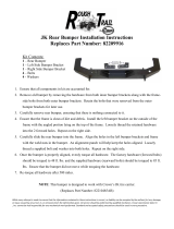
(3) 12mm x 50mm Hex Bolts
(6) 12mm Flat Washers
(3) 12mm Nylon Lock Nuts
(Fig 28) Attach Bumper to Mounting
Brackets (Fig 29) Passenger/right side
complete installation pictured
(Fig 30) Models with camera,
remove screen. Attach License
Plate to Bumper
(2) Plastic Plugs
Installation is now complete, check all hardware is
tightened and torqued to spec.

Visit www.trailfx.com or 1 (866) 638-4870 for Warranty Information / Tech Support / Product Updates.
2021 Keystone Automotive Operations Inc. All Rights Reserved. 12/08/2021-R01 Page-12 -13
PRODUCT CARE:
•Periodically check the product to ensure all fasteners are tight and components are intact.
•Use ONLY Non-Abrasive automotive wax. Use of any soap, polish or wax that contains an
abrasive is detrimental and can scratch the finish leading to corrosion.
•Mild soap may be used to clean the Black finish product.
FAQ’S
•Hardware and mounting brackets are not aligning properly
•Ensure that hardware is being used on the correct side of the vehicle. In some cases,
the hardware may appear same for driver or passenger side but may alter the alignment
of mounting location. Check mounting brackets for both sides.
•Products are thumping / rattling after installation
•Ensure that all required mounting brackets / hardware’s are installed & tighten
correctly. Suggest using white lithium / regular grease between metal-to-metal
contact.
•Missing / Excess Hardware
•Recheck hardware count as per the part list.
•Product not installing properly
•Ensure the Year / Make / Model as well as cab and bed dimensions are correct for the
application. Review all steps for installation to ensure they were followed correctly.
•Who should be contacted for questions regarding product / installation assistance?
•www.trailfx.com / suppo[email protected] 1-(866)638-4870

Visit www.trailfx.com or 1 (866) 638-4870 for Warranty Information / Tech Support / Product Updates.
2021 Keystone Automotive Operations Inc. All Rights Reserved. 12/08/2021-R01 Page-13 -13
Warranty Terms:
3 Year Limited Warranty:
TrailFX and Keystone Automotive Operations Inc. make no guarantees or warranties for products not
manufactured by Keystone Automotive Operations Inc. Such products are covered solely under any
applicable warranty of the manufacturer. It is always recommended that the operating instructions and
warranty instructions provided by the manufacturer are followed.
Keystone Automotive Operations Inc. warrants its products to be free from manufacturing and material
defects to the original purchaser for the length of warranty stated above from the date of retail purchase.
If any products are found to have a manufacturing or material defect, the product will be replaced or
repaired at the option of TrailFX and Keystone Automotive Operations Inc. with proof of purchase by the
original purchaser. The original purchaser shall pay all transportation and shipping costs associated with
the return of the defective product and the defective product shall become the property of Keystone
Automotive Operations Inc.
The Warranty applies to Keystone Automotive Operations Inc. products used for individual and
recreational purposes. Commercial usage of the Keystone Automotive Operations Inc. products limits the
warranty to 90-days from date of purchase.
The Warranty applies only to Keystone Automotive Operations Inc. products which are found to be
defective in manufacturing or material. This warranty does not apply to normal wear and tear of the finish
placed on Keystone Automotive Operations Inc. products.
TrailFX and Keystone Automotive Operations Inc. are not responsible for any labor costs incurred for
removal or replacement of the defective product.
TrailFX and Keystone Automotive Operations Inc. are not responsible for repair or replacement of any
product under the limited warranty where the product was improperly installed, misapplied, altered,
abused, neglected, overloaded, misused or damaged as a result of an accident, including any use of the
product not in accordance with all product operating and safety instructions.
Without limiting the generality of the foregoing, TrailFX and Keystone Automotive
Operations Inc. shall under no circumstances be liable for any incidental or consequential loss or damage
whatsoever arising out of, or in any way relating to any such breach of warranty or claimed defect in, or
non-performance of the products. Some states do not allow the exclusion or limitation of incidental or
consequential damages, so the above exclusion or limitation may not apply to you.
This limited warranty gives you specific legal rights, and you may also have other rights that vary from
state to state.
/