Page is loading ...

1 of 4
©2011 Tyco Electronics Corporation, a TE Connectivity Ltd. Company
All Rights Reserved
TE logo is a trademark.
*Trademark. Other products, logos, and company names might be trademarks of their respective owners.
Instruction Sheet
TOOLING ASSISTANCE CENTER
1-800-722-1111
PRODUCT INFORMATION
1-800-522-6752
This controlled document is subject to change.
For latest revision and Regional Customer Service,
visit our website at www.te.com
LOC B
408-7714
Universal MATE-N-LOK* Connectors
28 Mar 11 Rev F
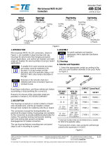
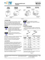
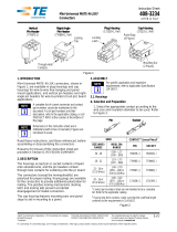
Figure 1
1. INTRODUCTION
This instruction sheet provides assembly procedures
for the Universal MATE-N-LOK housings and printed
circuit (pc) board headers listed in Figures 1, 2, and 3.
Dimensions in this instruction sheet are in metric
units [with U.S. customary units in brackets].
Figures are not drawn to scale.
NOTE
i
Reasons for reissue are provided in Section 8,
REVISION SUMMARY.
HOUSINGS
NUMBER OF
CIRCUITS
PLUG PART NUMBER CAP PART NUMBER TWISTLOK CAP PART NUMBER
NATURAL1WHITE2NATURAL1WHITE2NATURAL1WHITE2
1 350867 350865 770421 350866 - - - -
2•480698 350777 480699 350778 - - - -
3•480700 350766 480701 350767 - - - -
4•480702 350779 480703 350780 - - - -
5•480763 350809 480764 350810 - - - -
6•640585 640581 926307 926307 - - - -
6 480704 350715 480705 350781 794714 794760
8•640586 640582 926308 926308 - - - -
9 480706 350720 480707 350782 794715 794761
10•926302 926302 926309 926309 - - - -
12 480708 350735 480709 350783 794716 794762
15 480710 350736 480711 350784 - - - -
1 Natural colored housings are 94V-2 nylon material.
2 White colored housings are flame-retardant 94V-0 nylon material.
• In-line version
Plug Housing
Strain
Relief
Slot
Back of
Housing
(Wire End)
Locking Latch
Polarizing
Cavity
Identification
Rib
TwistLok Cap Housing
Cap Housing
Locking Tab
Polarizing
Cavity
Identification
Rib
Panel
Mount
Helix
Back of
Housing
(Wire End)
Back of
Housing
(Wire End)
Polarizing
Cavity
Identification
Rib Panel
Mount
Tabs
Panel Mount
Patch
Locking Tab

408-7714
2 of 4
Rev F
Figure 2
2. DESCRIPTION
A connector consists of either (1) a housing (plug or
cap) with a specified number of crimp contacts (pin or
socket); or (2) a pc board header preloaded with
solder tail contacts (pin or socket).
Mating connectors may be a plug and a cap, or a plug
and a pc board header, so long as both connectors
have an identical number of circuits with a pin contact
mating with a socket contact. Mating connectors are
fully polarized for proper engagement and employ a
positive locking feature to prevent accidental
disengagement.
VERTICAL PC BOARD HEADERS
NUMBER OF
CIRCUITS
HEADER
COLOR1
PIN HEADER PART NUMBER2SOCKET HEADER PART NUMBER2
STD TAIL3STD TAIL
PLZD3LONG TAIL4STD TAIL3STD TAIL
PLZD3LONG TAIL4
2•NATURAL 350428 641963 350582 350759 643411 350986
2•WHITE 350786 641964 350787 350824 643412 350831
3•NATURAL 350429 641965 350583 350760 643413 350987
3•WHITE 350789 641966 350790 350825 643414 350832
4•NATURAL 350430 641967 350584 350761 643415 350988
4•WHITE 350792 641968 350793 350826 643416 350833
5•NATURAL 640466 643405 - - 640467 - - - -
5•WHITE 640900 643406 - - 640901 - - - -
6•NATURAL 641832 643407 - - - - - - - -
6•WHITE 641831 643408 - - 770262 - - - -
6 NATURAL 350431 - - 350585 350762 643423 350989
6 WHITE 350711 641970 350732 350827 643424 350834
8•NATURAL 641825 - - 770143 - - - - - -
8•WHITE 641828 643410 - - - - - - - -
9 NATURAL 350432 641971 350586 350763 643425 350990
9 WHITE 350712 641972 350742 350828 643426 350835
12 NATURAL 350433 641973 350587 350764 - - 350991
12 WHITE 350713 641974 350737 350829 643428 350836
15 NATURAL 350434 641975 350588 350765 643429 350992
15 WHITE 350714 641976 350738 350830 643430 350837
1 Natural colored housings are 94V-2 nylon material. White colored housings are flame-retardant 94V-0 nylon material.
2 Base numbers shown. Dash numbers indicate contacts with a pre-tin finish or a duplex finish.
3 Use standard tail (and standard tail polarized) for 1.57 [.062] thick pc board.
4 Use long tail for 3.18 [.125] thick pc board.
• In-line version.
Vertical PC Board Header
(Pin or Socket)
Front of Header
(Mating End)
Cavity Identification
Locking Tab
Solder Tail (Typ)

408-7714
3 of 4
Rev F
The plug and cap housings are available with 1
through 15 circuits and accept pin and socket crimp
contacts and programmable socket contacts (see
Figure 5). Both the plug and the cap housings have
individually numbered cavity identification on the
BACK (wire end), plus an identification rib on the SIDE
indicating the Number 1 cavity.
The housings feature polarizing cavities on the mating
end. The plug housing has two locking latches and the
cap housing has two locking tabs. The housings are
designed for free hanging or panel mounting
applications (refer to Section 5, PANEL CUTOUT).
The pc board headers are supplied preloaded with
solder tail pin contacts or solder tail socket contacts.
Vertical pin and socket headers are available in 2
through 15 circuits. Vertical headers are designed for
either 1.57 mm [.062 in.] thick pc boards (standard
solder tail length), or 3.18 mm [.125 in.] thick pc
boards (long solder tail length). Right-angle pin and
socket headers are available in 2 through 8 circuits. All
headers feature individually numbered cavity
identification on the FRONT (mating end), polarizing
cavities, and locking tabs. Refer to Section 6,
PRINTED CIRCUIT BOARD LAYOUT.
Figure 3
3. TEST CONNECTORS (FIGURE 4)
Plug and cap test connectors are designed to mate
with respective assembled plug and cap connectors
and headers to test the electrical circuit. The test
connectors are preloaded with spring-loaded contacts
that will mate with pin or socket contacts in the
connector. The 2.13 mm [.084 in.] diameter pin that
extends out the BACK of the test connector will accept
Universal MATE-N-LOK socket contacts.
Figure 4
4. ACCESSORIES
Keying Plugs - Keying plugs provide additional
polarization for the connectors. Refer to Instruction
Sheet 408-3320 for insertion procedures.
Strain Relief Assembly - The strain relief assembly is
designed to relieve the stress of the wires on the
contacts. There are two strain relief versions (open
and enclosed). Refer to Instruction Sheet 408-3320 for
assembly procedures.
5. PANEL CUTOUT
The cap housing features flexible mounting latches
and is designed for panel mounting. The TwistLok cap
housing has a panel mount helix and is designed to
insert into a panel by twisting clockwise until seated.
Refer to the customer drawing or Application
Specification 114-1010 for cutout dimensions.
6. PRINTED CIRCUIT BOARD LAYOUT
Headers are designed to be mounted and soldered
onto pc boards. Refer to the customer drawing or
Application Specification 114-1010 for layout
dimensions.
RIGHT-ANGLE PC BOARD HEADERS1
NUMBER OF
CIRCUITS
PIN HEADER
PART NUMBER2
SOCKET HEADER
PART NUMBER2
2 350942 643226
3 350943 643228
4 350944 643230
5 350945 643232
6 640583 643234
8 640584 643236
1 All housings are white colored, flame-retardant, 94V-0, nylon material.
2 Base numbers shown. Dash numbers indicate contacts with a pre-tin finish or
a duplex finish.
Right-Angle PC Board
Header (Pin of Socket)
Cavity
Identification
Locking Tab
Mounting Ears (Use 6-32 UNC
Pan HEad Screws 3/8-In. Long
- Not Supplied)
TEST CONNECTORS•
NUMBER OF
CIRCUITS
PLUG PART
NUMBER
CAP PART
NUMBER
2 350848-2 350849-2
3 350848-3 350849-3
4 350848-4 350849-4
5 350848-5 350849-5
6 350848-6 350849-6
9 350848-9 350849-9
12 1-350848-2 1-350849-2
15 1-350848-5 1-350849-5
• All housings are white colored, flame-retardant, 94V-0, nylon material. The
test connectors have a 5 amp maximum current rating per circuit.
Test Connectors 2.13 [.084] Dia Pin (Typ)
Plug Cap
2.13 [.084] Dia Pin (Typ)

408-7714
4 of 4
Rev F
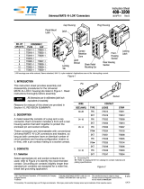
Figure 5
7. CONTACTS (FIGURE 5)
7.1. Selection
Refer to Figure 5 for wire size and pin and socket
compatibility.
Pin and socket crimp contacts are available in strip
form for machine crimping, and in loose piece form for
hand tool crimping. Split pin contacts are
recommended for use in housings having 6, 9, 12, and
15 circuits to reduce mating force. Grounding pin
contacts (2.54 mm [.100 in.] longer than standard pin
contacts) are designed for a mate first, break last
grounding application. Programmable socket contacts
are designed to accept 110 Series FASTON*
receptacle terminals.
7.2. Crimping
Follow termination procedures shown in Application
Specification 114-1010.
Strip form contacts are designed to be crimped with a
heavy duty miniature applicator in a semi-automatic or
automatic machine. Consult your local Representative
for assistance in selecting the machine that will best
suit your needs.
Loose piece contacts are designed to be crimped with
a hand crimping tool. Read the instruction sheet
packaged with the tool for the proper crimping
procedure.
7.3. Insertion
An insertion tool is generally NOT required for
inserting contacts into the housings. Pin and socket
contacts may be inserted in either the plug or the cap
housing, or they may be intermixed in each housing to
provide additional keying combinations.
Insertion Tool 455830-1 is available for inserting
contacts crimped to small wire sizes. Refer to
Instruction Sheet 408-7984 for insertion procedures.
7.4. Extraction
Extraction Tool 318851-1 is designed for removing pin
and socket contacts from plug and cap housings.
Refer to Instruction Sheet 408-4371 for extraction
procedures.
7.5. REVISION SUMMARY
Revisions to this instruction sheet include:
•Updated document to corporate requirements.
WIRE SIZE
(AWG)
CONTACT
TYPE
LOOSE PIECE
PART
NUMBER
STRIP PART
NUMBER
30 to 26 Pin 770672 350924
Skt 770673 350925
24 to 18
Pin 350690 350561
Skt 640347 350851
Skt 350689 350570
Pin•350706 350699
Pin•• - - 770210
20 to 14
Pin 350547 350218
Skt 350550 350536
Pin•350705 350687
Pin•• 350669 350654
Pin 350552 350538
Skt 350551 350537
Pin•350707 350700
18 to 14 Pin 350918 350873
Skt 350919 350874
12 to 10
Pin 640309 350922
Skt 640310 350923
Pin•• - - 770234
• Split pin •• Grounding pin - 2.54 [.100] longer than standard pin.
Pin
Socket
Split Pin
Contact Programmable
Socket Contact
350877
Locking Lance
(Typ)
/

